Gram K3 Operation Manual
Hide thumbs
Also See for K3:
- Operation manual (44 pages) ,
- User manual (44 pages) ,
- Quick start manual (9 pages)
Table of Contents
Advertisement
Advertisement
Table of Contents

Related Manuals for Gram K3


Summary of Contents for Gram K3
-
Page 3: Table Of Contents
INDEX KEYPAD AND LCD DISPLAY ................ 5 BEFORE USING THE SCALE ................ 8 ON / OFF ....................10 INITIAL RESET TO ZERO ................10 OPERATION ..................... 11 5.1. USE OF THE SCALE ............... 11 5.2. TARE AND TARE RECORD IN MEMORY ........12 5.3. - Page 4 17. WEIGHING OF LIVE ANIMALS ..............43 18. MOVEMENT FILTER ................. 43 19. INFORMATION TO BE VIEWED ..............44 20. DIGITAL OUTPUTS ................... 44 21. TECHNICAL SPECS ..................46 22. CONNECTIONS ..................48 23. ERROR MESSAGES ................... 50 24. NOTES ...................... 51...
-
Page 5: Keypad And Lcd Display
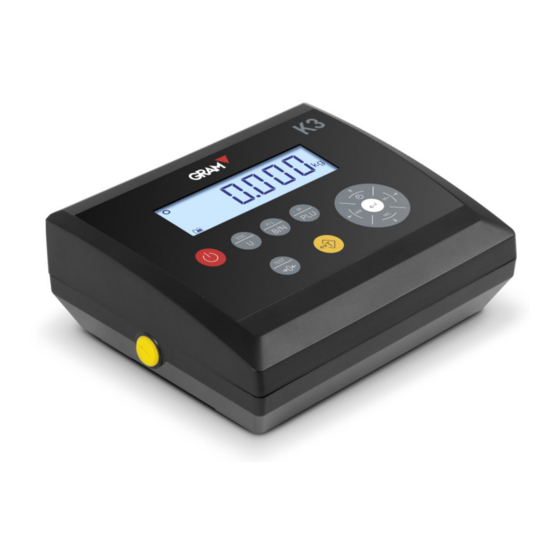
1. KEYPAD AND LCD DISPLAY Switches the unit On / Off. Pressing it lights up the indicator. With the indicator on, keeping it pressed for two seconds switches it off. Piece counter mode. Activates or deactivates the piece counter mode. Double-pressing it gives access to the options menu of the piece counter mode. - Page 6 software version. Double-pressing the key activates the high- resolution mode. When editing the value of an alphanumerical data, it switches between upper case, lower case and numbers / symbols. Tare. Pressing it once subtracts the weight of any receptacle or box placed on the platform until the weight is removed from the platform and this key is pressed again.
- Page 7 Displays the weight on the scale platform. In HOLD mode, the reading is shown intermittently to signal that it is not indicating the real weight on the scale but the latest stable weight recorded. Unit of measurement in which the weight is indicated. Piece counter mode: The display shows the number of units, not the weight.
-
Page 8: Before Using The Scale
5. Connector for the XTREM platform Connect the AC/DC power source to the unit and to a power outlet suitable for charging the battery before its first use. Connect the load receptor platform cable in the C1 connector of the K3 indicator. - Page 9 Before using the scale, check the bubble level included in the actual platform and adjust the levelling feet if necessary. Both the K3 indicator and the weight sensors included in the platform are sensitive to changes in ambient temperature. To achieve maximum precision, we recommend you keep the scale switched on for at least 30 minutes in its set-up site before using it.
-
Page 10: On / Off
3. ON / OFF Press on the key. The display switches on and performs the following sequence: 1. All segments and symbols switch on for a second on the LCD display to verify that they are functioning properly. 2. It then shows the unit’s firmware version code during one second. 3. -
Page 11: Operation
5. OPERATION 5.1. USE OF THE SCALE Once the unit is switched on, the weight display will indicate that the scale: • is set to zero, meaning that there is no load placed on the platform. • the reading is stable, that is to say, there is no external influencing factor (such as an air current or the vibration of a nearby engine) that may be producing significant disruption. -
Page 12: Tare And Tare Record In Memory
“fixed tare” to “normal tare”. The default operating mode for tare is “preset tare”, although this value can be changed in the options menu (see option It is possible to apply a tare previously memorized in the unit. The K3 indicator has up to 20 tare records, numbered from 1-20. Double-press the tare key to access this record and select one of the memorized tares. - Page 13 (“value”) option; pressing on the key will display the tare value associated to the selected record. If no value has previously been entered for the selected record, the K3 indicator will show the current weight on the scale in the field for editing.
-
Page 14: Zeroing
5.3. ZEROING Zeroing the scale: A short press on this key sets it to zero. The scale is deemed to be “set to zero” when the weight on the load receptor is lower than ¼ of division. While the scale is “set to zero”, the reading is shown in the display. -
Page 15: High-Resolution Mode
5.5. HIGH-RESOLUTION MODE Double-pressing the TEST key activates the high-resolution mode. In this mode the scale’s resolution is enlarged by x10, allowing the weight to be viewed with a 10-times-smaller division. An additional digit appears in the weight display, and the decimal point is shifted to the left by one position. -
Page 16: H-L Mode (Control Of Upper/Lower Limits)
5.7. H-L MODE (CONTROL OF UPPER/LOWER LIMITS) Keeping this key pressed for more than one second activates or deactivates the upper and lower limit control mode. For an instant, the display shows the message to indicate that it has been activated, or the message to indicate that it has been deactivated. -
Page 17: Dosage Mode
(K2 relay contact) stays closed. To stop and pause a dispense cycle being run, press on the “tare” key. This action will open the K1 and K3 relay contacts, halting the filling until the tare key is pressed again. -
Page 18: Piece Counter Mode
The number of pieces is calculated by dividing the net weight on the scale by a unit weight value. The K3 indicator has a memory space for 20 unit weight records. When pressing on the “U” key and changing to piece counter mode, the... - Page 19 In piece counter mode, all of the scale’s functions remain available: tare and memorized tare, high resolution, limit control, PLU selection, ticket printing or adhesive label. If limit control mode is activated, the value for the lower limit and for the upper limit refers to the number of pieces, not to the net weight on the scale.
-
Page 20: Plu - Selection Of Product Code
When pressing on the PLU key, the indicator jumps to the product codes configuration menu to select or edit a record. The K3 indicator has a memory with 85 PLU records. This memory allows a 6-character alphanumerical information field to be associated to each one of these records. -
Page 21: Printing A Weighing Ticket
5.11. PRINTING A WEIGHING TICKET In “weight indicator” mode and in “piece counter” mode, the key acts as a print key. When pressing this key, a ticket is printed with the weight shown on the LCD display. The ticket shows print date and time, the ticket’s serial number, gross weight, tare and net weight. - Page 22 The print key will only be effective if the weight on the scale is stable (the stability indicator is switched on). This gross/tare/net ticket is only possible provided no ticket with accumulated total has been initiated, which has a different format. To initiate a totalizer ticket, weigh the first object to be included in the ticket and press the M+ key.
-
Page 23: Configuration Options Menu
6. CONFIGURATION OPTIONS MENU To access the configuration options menu, keep the “M” key pressed for two seconds. The display shows the message for ½ second to indicate that from then on the indicator will start showing the different selection options. In “menu” mode, use the arrow keys to change to the next option or change the value of one digit in the display when editing the value of a parameter. - Page 24 La siguiente tabla resume las diferentes opciones de configuración y ajuste: • Options for automatically switching off the unit • Options for backlighting the LCD display • Activating sound when pressing on a key ...
- Page 25 • Activating zero-tracking device • Activating zero reading Procedure for calibrating the scale • Activating automatic correction depending on geographical location ...
-
Page 26: Auto-Off Option
7. AUTO-OFF OPTION This option programs the device’s automatic switch-off after a time on idle (not being used). The device is understood to be on idle if there is no variation in the weight indication, and no key is pressed. The possible options are the following: The device always remains switched on. -
Page 27: Sound When Pressing A Key
9. SOUND WHEN PRESSING A KEY This function activates (“On”) or deactivates (“Off”) the emission of a sound when one of the keypad buttons is pressed. The factory setting for this option is “On”. TARE OPTIONS The possible options are: Preset tare: The tare will be kept until the tare key is pressed again with an empty load receptor platform. - Page 28 To select the desired hold mode, keep the key pressed until the LCD display shows the message giving access to the options in the configuration menu. Press the → key until the display shows the option and then press the ...
-
Page 29: Keypad Lock
2 seconds . 13. COMMUNICATION The K3 indicator can be connected to other devices to send and receive information via an RS-232 interface (standard) or a Wi-Fi 802.11 interface (optional). The K3 indicator can have up to 2 serial RS232 outputs. The second serial output is supplied optionally. - Page 30 Configuration of serial port 1. Configuration of serial port 2. Each one of the serial ports is configured independently, allowing different devices with differentiated running modes to be connected. The configuration options available are the following: Mode in which the data transmission will be made: •...
- Page 31 Frame data in a compatible format with the GRAM model Z3 weight indicator. For connecting to PC with Virtual Key application. Frame data in a format for the GRAM USB adapter cable. Frame data in a format for the GRAM USBFR adapter cable (emulating “AZERTY” keypad).
-
Page 32: Remote Indicator Mode
13.1. Remote indicator mode The K3 indicator can operate as a remote display for another scale by using the “GRAM remote” communication protocol. When a K3 indicator is not configured as a remote indicator, it obtains the weight information from another scale via the RS232 serial port. -
Page 33: Pr4/Pr6/Q2 Printer
9600 bauds, both for the K3 indicator and for the XTREM weight transmitter. If necessary, to return to the operating mode of the K3 as an analogue weight indicator and to have access to the options and configuration menu, press the following keys at the same time: 13.3. -
Page 34: Frame Format Usb
Format compatible with the GRAM USB adapter for PC-type computer with Microsoft Windows operative system. From the PC’s point of view, the GRAM USB adapter is a keypad emulation that transforms the information transmitted by indicator K3 into a keypad input. - Page 35 The status byte is built from the binary values of the display indications (tare, zero, gross/net and stability). 20h is added to the result to ensure that the result is printable. Bit 0 (01h) The transmitted value is the gross weight. Bit 1 (02h) A tare is set.
- Page 36 The status byte is 63h (‘c‘) 63h – 20h = 43h ➔ Bit 7 Bit 6 Bit 5 Bit 4 Bit 3 Bit 2 Bit 1 Bit 0 (stable) (no zero) (Tare on) (Gross) The status byte is 6Ah (‘j‘) 6Ah –...
-
Page 37: Communication Protocol
13.7. Communication protocol The K3 indicator is equipped with a communication protocol that allows the unit to be commanded remotely. The table below lists the available commands and the response of the K3 indicator. COMMAND RESPONSE Returns a message with the identification of the “GRAM K3 Vxxxx”... -
Page 38: Ticket Print Options
TICKET PRINT OPTIONS This menu has various options for configuring the information that appears printed in the tickets generated by the K3 indicator. Setting the time on the scale’s internal clock. Only if the optional real-time clock board is installed. -
Page 39: Configuring The Scale
15. CONFIGURING THE SCALE This menu features the options for parameterizing and setting the measurement scale of the instrument. Measurement unit: g, kg, oz, lb. Maximum capacity of the scale. Enter the value, including the decimal digits. Division: The smallest increment that the instrument can measure. -
Page 40: Settings Menu
15.1. Settings menu The settings menu can be directly accessed when switching on the unit. To do this, switch on the unit and, while the LCD test appears with all segments on, at the same time press on the keys (a short press, not sustained). - Page 41 3. Once the zero value has been calibrated, place the calibration weight (a known mass weight) on the load receptor. 4. Enter the weight value in the indicator, including the decimal positions. Use the cursor movement keys to move through the different positions on the display.
-
Page 42: Table Of Geographical Adjustment Values
16.3 Table of geographical adjustment values Elevation above sea level in metres 1300 1625 1950 2275 2600 2925 3250 Geographical latitude in 1300 1625 1950 2275 2600 2925 3250 3575 the northern or southern Elevation above sea level in feet hemisphere in degrees and minutes. -
Page 43: Digital Filter
16. DIGITAL FILTER Every 100ms, the A/D converter of the S2 scale provides a reading of the electrical output voltage of the connected load cell. The digital filter consists of a moving average of these readings. Possible values are 1 (moving average of 2 readings), 2 (4 readings), 3 (8 readings), or 4 (16 readings). -
Page 44: Information To Be Viewed
The K1 relay closes when the weight on the scale is greater than the limit . The K2 relay closes when the weight is between the limits. The K3 relay closes when the weight is below the value. The relay outputs will be controlled by the dosage mode. - Page 45 Allows each one of the 3 relays to be checked and operated by the user. Setting the upper and lower values for running the “checkweigher” mode. Value of the lower limit, including the decimal part. Value for the upper limit, including the decimal part.
-
Page 46: Technical Specs
21. TECHNICAL SPECS Load cell connection Maximum input signal ±4 mV/V Maximum input voltage -0.3 to 5.3 V Internal resolution AD 20bits converter, 1000000 counts (100000 external) Measurement frequency 10 samples per second Linearity error ≤0.01% of the measurement range Exciting voltage 5 Vdc Minimum transducer... - Page 47 Size (mm) 220 x 180 x 83 Weight (kg) 1.5 (including battery) Assembly Desktop Optional: Swivel mount wall/column Tightness IP-65 (K3); IP-67 (K3i) Thermal printer (K3iP and MK3P models) Printer life 6000000 printed lines Resolution 8 dots/mm Print speed 30 mm/sec Paper type Thermal paper reel (57mm wide, 30 mm ø)
-
Page 48: Connections
22. CONNECTIONS C1 connector, load cell PIN No. SIGNAL TYPE A TYPE B PIN 1 SIG - Blue White PIN 2 SIG + Brown Green PIN 3 MESH Mesh Mesh PIN 4 EXC - Black Black PIN 5 SENSE - Blue 4 MULTI-PIN MOBILE MALE (P700) 7 PINES... - Page 49 RS-232 serial output PIN No. SIGNAL PIN 4 PIN 5 PIN 6 5 MULTI-PIN MOBILE MALE (P700) 8 PINES XTREM scale connector SIGNAL PIN No. PIN 1 +Vcc PIN 2 PIN 3 PIN 4 No conectado PIN 5 6 MULTI-PIN MOBILE MALE (P700) 5 PINES...
-
Page 50: Error Messages
23. ERROR MESSAGES ADC fault: No response from Malfunction in scale. Consult ADC. helpdesk. Sensor input signal too high Faulty load cell. Cabling in (>20mV). poor condition. Sensor input signal too low Faulty load cell. Cabling in (<-20mV). poor condition. Dead battery. -
Page 51: Notes
24. NOTES _______________________________________________________________ _______________________________________________________________ _______________________________________________________________ _______________________________________________________________ _______________________________________________________________ _______________________________________________________________ _______________________________________________________________ _______________________________________________________________ _______________________________________________________________ _______________________________________________________________ _______________________________________________________________ _______________________________________________________________ _______________________________________________________________ _______________________________________________________________ _______________________________________________________________ _______________________________________________________________ _______________________________________________________________ _______________________________________________________________ _______________________________________________________________ _______________________________________________________________ _______________________________________________________________ _______________________________________________________________ _______________________________________________________________ _______________________________________________________________ _______________________________________________________________ _______________________________________________________________ _______________________________________________________________ _______________________________________________________________ _______________________________________________________________ _______________________________________________________________ _______________________________________________________________... - Page 52 003/25032019...
Need help?
Do you have a question about the K3 and is the answer not in the manual?
Questions and answers