Table of Contents
Advertisement
Advertisement
Table of Contents

Subscribe to Our Youtube Channel
Related Manuals for Gram K3X Series


Summary of Contents for Gram K3X Series
- Page 1 K3X / K3iX / K3iX P...
-
Page 3: Table Of Contents
INDEX KEYPAD AND LCD DISPLAY ................ 5 BEFORE USING THE SCALE ................ 8 ON / OFF ....................10 INITIAL ZERO SETTING ................10 SOFTWARE VERSION IDENTIFICATION ............ 11 OPERATION ..................... 12 6.1. USE OF THE SCALE ............... 12 6.2. TARE FUNCTION ................13 6.4. -
Page 5: Keypad And Lcd Display
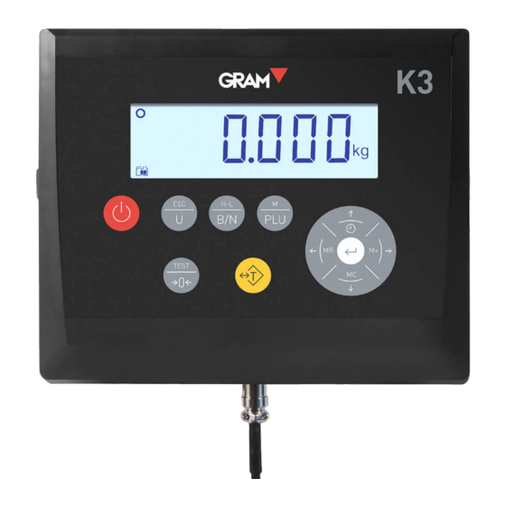
1. KEYPAD AND LCD DISPLAY Switches the device On / Off. Press once to switch the scale on. Hold the key down for 2 seconds to switch off the scale. Esc / Menu. It enters the menu settings mode. When already into the settings menu mode, escapes to the previous menu option or back to the weighing mode. - Page 6 Left / Right arrow. Selects and edit a tare memory record. → Print / Enter. When in “Weighing mode” prints the current weighing data (simple ticket mode). When clicking twice, starts printing a totalisation ticket. When holding pressed for 2 seconds, ends the current totalisation ticket.
- Page 7 LCD display symbols and readings: Displays the weight on the scale platform. Unit of measurement in which the weight is indicated. Stable weight reading: There is a weight on the platform that is not fluctuating. Intermittent or switched off to indicate that there is movement in the scale. Negative sign.
-
Page 8: Before Using The Scale
2. BEFORE USING THE SCALE 1. AC/DC adapter, output 12 Vdc – 1 A 2. Space allocated for additional options. 3. RS-232 data output. 4. Connector for the XTREM platform. Attach the AC/DC power source to the unit and to a mains power outlet for charging the battery before its first use. - Page 9 The load receptor platform should be placed on a flat surface free of any irregularities. For the proper functioning of the instrument, the platform should be horizontally levelled. Before using the scale, check the bubble level mounted on the platform structure and adjust the levelling feet if necessary. Both Xtrem module and the weight sensors mounted on the platform are sensitive to changes in ambient temperature.
-
Page 10: On / Off
3. ON / OFF Press on the key. The display switches on and performs the following sequence: 1. All segments and symbols switch on for a second on the LCD display to verify that they are functioning properly. 2. It then shows the unit’s firmware version code during one second. 3. -
Page 11: Software Version Identification
5. SOFTWARE VERSION IDENTIFICATION Firmware version is V 6.xxx, where “xxx” is referred to different functions which doesn’t affect legally relevant parameters. K3X terminal display shows for 2” the embedded software version after power on. Full information on K3X terminal module and Xtrem ADPD module can be show on the LCD display by following next steps: Press to enter the menu... -
Page 12: Operation
6. OPERATION 6.1. USE OF THE SCALE Once the unit is switched on, the weight display will indicate that the scale: • is set to zero, meaning that there is no load placed on the platform. • the reading is stable, that is to say, there is no external influencing factor (such as an air current or the vibration of a nearby engine) that may be producing significant disruption. -
Page 13: Tare Function
6.2. TARE FUNCTION A short press on this key activates the tare function: The scale memorizes the weight currently on the load receptor and subtracts it from the total weight until the tare function is deactivated or cancelled. The tare function only operates if the weight is stable. If the stability indicator is switched off, pressing this key has no effect. - Page 14 6.3. MEMORY TARE RECORDING It is possible to apply a tare previously memorized in the equipment. The indicator has up to 20 tare records, numbered from 1 to 20. Use the and → keys to access this register and select one of the stored tares.
-
Page 15: Zero Setting
6.4. ZERO SETTING A short press on this key sets the scale to zero. The scale is deemed to be “set to zero” when the weight on the load receptor is lower than ¼ of division. While the scale is “set to zero”, the reading is shown in the display. -
Page 16: H-L Mode (Control Of Upper/Lower Limits)
6.6. H-L MODE (CONTROL OF UPPER/LOWER LIMITS) Activates or deactivates the upper and lower limit control mode. For an instant, the display shows the message to indicate that it has been activated, or the message to indicate that it has been deactivated. When the limit control is activated, a reading lights up in the bottom part of the LCD display to signal whether the net weight on the plate is lower than value or higher than the... -
Page 17: Dosing Mode
6.7. DOSING MODE The dosing mode is activated and configured by accessing the options menu in the section (see section 16 in this manual). Pressing the tare key initiates the dosing cycle, closing the K1 and K3 relay contacts. The display changes to blue to indicate that the dosing cycle has been initiated. -
Page 18: Printing A Single Weighing Ticket
6.8. PRINTING A SINGLE WEIGHING TICKET Pressing this key when in “weighing mode”, will print the current weighing information (single weighing ticket). The print key will only be effective if the weight on the scale is stable (the stability indicator is switched on). A short press on this key will print a ticket with the following information: date and time, the Xtrem scale identification, the ticket’s serial number, gross weight, tare, and net weight (just the weight when not using the tare... -
Page 19: Printing A Totalizer Ticket
6.9. PRINTING A TOTALIZER TICKET Double press the print key will starts printing a totalizer ticket. When holding pressed for 2 seconds, prints the current total and exits the totalizer function. The print key will only be effective if the weight on the scale is stable (the stability indicator is on). -
Page 20: Configuration Options Menu
7. CONFIGURATION OPTIONS MENU To access the configuration options menu, press the “M” key. The display shows the message for 1 second to indicate that from then on, the indicator will start showing the different setting options. In “menu mode”, use the arrow keys to change to the next option or change the value of one digit in the display when editing the value of a parameter. - Page 21 The table below summarizes the different configuration options: • Automatic shutdown options • Backlight options • Beep ON/OFF • Tare mode : Pre-set / normal tare ...
- Page 22 … Filter level • Additional filter for weighing livestock • Motion filter(ON/OFF) Changes AD/C sampling speed Frequency for sending weight information to the terminal ...
-
Page 23: Auto-Off Option
8. AUTO-OFF OPTION This option programs the device’s automatic switch-off after a time on idle (not being used). The device is understood to be on idle if there is no variation in the weight indication, and no key is pressed. The possible options are the following: The device always remains switched on. -
Page 24: Sound When Pressing A Key
10. SOUND WHEN PRESSING A KEY This function activates (“On”) or deactivates (“Off”) the emission of a sound when one of the keypad buttons is pressed. The factory setting for this option is “On”. 11. TARE OPTIONS The possible options are: Pre-set tare: The tare will be kept until the tare key is pressed again with an empty load receptor platform. -
Page 25: Data Output
For connecting to PC with Virtual Key application. Data in a format for the GRAM USB adapter cable. Frame data in a format for the GRAM USBFR adapter cable (emulating “AZERTY” keypad). Connection to Q2 label printer. A ticket is sent in a format... -
Page 26: Pr4/Q2 Printer
Format compatible with the GRAM USB adapter for PC-type computer with Microsoft Windows operative system. From the PC’s point of view, the GRAM USB adapter is a keyboard emulation that transforms the information transmitted by K3X terminal into a keyboard input. -
Page 27: Frame Format Pc0
12.3. Frame format PC0 The indicator sends the following byte frames (always 14 bytes in length). 02h 69h 20h 20h 20h 30h 2Eh 30h 30h 30h 6Bh 67h 0Dh 03h STX ‘I’ spc spc spc 0 0 Start of text. 1 Status (tare, zero, net, stable, unstable). - Page 28 Examples: The status byte is 61h (‘a‘) 61h – 20h = 41h ➔ Bit 7 Bit 6 Bit 5 Bit 4 Bit 3 Bit 2 Bit 1 Bit 0 (stable) (no zero) (Tare off) (Gross) The status byte is 69h (‘i‘) 69h –...
- Page 29 The status byte is 6Ah (‘j‘) 6Ah – 20h = 4Ah ➔ Bit 7 Bit 6 Bit 5 Bit 4 Bit 3 Bit 2 Bit 1 Bit 0 (stable) (zero) (Tare on) (Net) The status byte is 6Bh (‘k‘) 6Ah – 20h = 4Ah ➔ Bit 7 Bit 6 Bit 5...
-
Page 30: Ticket Printing Options
13. TICKET PRINTING OPTIONS This menu has various options for configuring the information that appears printed in the tickets generated by the K3X terminal. Setting the time on the scale’s internal clock. Value of the next ticket number to be printed. It is automatically increased with each print, whether it is a single ticket or a ticket with accumulated total. -
Page 31: Scale Setup And Calibration
14. SCALE SETUP AND CALIBRATION At the menu you view and configure the settings needed to define and adjust the measurement scale of the instrument. Access to these configuration options is reserved for technical personnel and is protected by a keyword to avoid accidental changes that would cause the instrument to malfunction. -
Page 32: Double Range / Interval Configuration
14.1. Double range / interval configuration. Xtrem scale can be configured as a 2-ranges or 2-interval instrument using the settings on the menú. Select the function mode: (the scale will work as a single range instrument), (the scale will work as a 2 ranges instrument, (the scale will work as a 2 interval instrument). -
Page 33: Scale Calibration
14.3. Scale calibration For the calibration of the scale, it is recommended to use a standard weight. Calibration procedure using a known weight (automatically sets the initial zero and the slope value). Gravity adjustment depending on the scale’s geographical location: ON / OFF correction (activates/deactivates automatic correction according to geographical location). - Page 34 5. Once you enter the weight value, double-press on the key to validate and move to next step. The display will show the blinking message “ “ while acquiring the calibration value. 6. Lastly, it will show the message “ ”...
-
Page 35: Table Of Geographical Adjustment Values
16.3 Table of geographical adjustment values Elevation above sea level in metres 1300 1625 1950 2275 2600 2925 3250 Geographical latitude in 1300 1625 1950 2275 2600 2925 3250 3575 the northern or southern Elevation above sea level in feet hemisphere in degrees and minutes. -
Page 36: Filtering Settings
15. FILTERING SETTINGS Filtering options allow the scale to be configured for use in harsh environments or for weighing moving products, such as liquid tanks or live animals. Possible values are from 1 up to 7. A smaller filter level value implies that rapid oscillations in the weight become more visible and vice versa. -
Page 37: Digital Outputs Configuration
16. DIGITAL OUTPUTS CONFIGURATION This section allows the configuration of the optional 3-relay board available for the K3X terminal. These 3 relay outputs can be used either for controlling an external signalling of the high/low/ok limits in the operation mode as a checkweigher (H-L mode) or for dosing a product. - Page 38 Setting of values for dosing operation. Weight set point for speed 1. Weight set point for speed 2. Type of dosing. Loading ( ) or unloading Yes / No: Activating the dosage mode when switching on the unit.
-
Page 39: Technical Specs
17. TECHNICAL SPECS User interface Main indicator 6-digit LCD 25.4 mm in height and weight limits visualizer. Backlit 3-LED (RGB) backlit panel Keypad 11-key keypad Acoustic warning Piezoelectric intermittent-sound mini-buzzer (2300±300 Hz y 85 dB) Real time clock Date and time (hours, minutes, seconds). Battery backup using a CR2032 3V Serial RS232C output (K3X and K3iX models) RS232 port (not available... - Page 40 Power Connection to the AC/DC adaptor: Input 100-240Vac, 50-60Hz, 0,6A mains Output 12Vdc -1 A Battery 6V-5AH; Service time 25/60 hours depending on use. Operating conditions and mechanical data Operational C/+40 temperature range Size (mm) K3X 220 x 180 x 83 mm K3iX 225 x 195 x 111 mm K3iXP 225 x 195 x 121 mm Weight (including...
-
Page 41: Connections
18. CONNECTIONS RS-232 serial output PIN No. SIGNAL PIN 4 PIN 5 PIN 6 NOTE: Not present in K3iXP model. 5 MULTI-PIN MOBILE MALE (P700) 8 PINES XTREM scale connector PIN No. SIGNAL PIN 1 +Vcc PIN 2 PIN 3 PIN 4 Not connected PIN 5... -
Page 42: Error Messages
19. ERROR MESSAGES A/D default: No response Xtrem ADPD module damaged. from the A/D converter. Load cell input signal too high (>20mV). Load cell input signal too low Check the scale for some load (<-20mV). cell / wiring default. Load cell input signal out of range (>30mV) Load cell excitation and A/D converter switched off... -
Page 43: Notes
20. NOTES _______________________________________________________________ _______________________________________________________________ _______________________________________________________________ _______________________________________________________________ _______________________________________________________________ _______________________________________________________________ _______________________________________________________________ _______________________________________________________________ _______________________________________________________________ _______________________________________________________________ _______________________________________________________________ _______________________________________________________________ _______________________________________________________________ _______________________________________________________________ _______________________________________________________________ _______________________________________________________________ _______________________________________________________________ _______________________________________________________________ _______________________________________________________________ _______________________________________________________________ _______________________________________________________________ _______________________________________________________________ _______________________________________________________________ _______________________________________________________________ _______________________________________________________________ _______________________________________________________________ _______________________________________________________________ _______________________________________________________________ _______________________________________________________________ _______________________________________________________________ _______________________________________________________________...
Need help?
Do you have a question about the K3X Series and is the answer not in the manual?
Questions and answers