
Related Manuals for Brainchild C91


Summarization of Contents
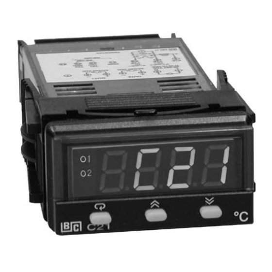
Chapter 1 Overview
General Information
Overview of the microprocessor-based controller series with LED display and fuzzy logic technology.
Key Features
Details key features like accuracy, sampling rate, fuzzy control, and digital communication capabilities.
Controller Functions
Explains essential functions like programming port, auto-tune, lockout, bumpless transfer, ramp, and digital filter.
Ordering Code
Details the coding system used for ordering different configurations of the controller.
Keys and Displays
Explains the function of each key and the display elements on the controller's front panel.
Menu Overview
Illustrates the menu structure and navigation flowcharts for controller setup and calibration.
Parameter Descriptions
Provides a detailed list and descriptions of all available parameters for controller configuration.
Chapter 2 Installation
Unpacking and Mounting
Instructions for unpacking the controller unit and inspecting for shipping damage.
Wiring Precautions
Critical precautions to follow before and during wiring to ensure safe and correct installation.
Power and Sensor Installation
Explains power wiring and provides guidelines for optimal sensor placement.
Input and Output Wiring
Illustrates wiring diagrams for sensor input and control output connections.
Alarm Wiring
Illustrates how to wire alarm outputs to drive loads or contactors.
Data Communication
Details the wiring requirements for RS-485 and RS-232 data communication interfaces.
Chapter 3 Programming
Lockout and Signal Input
Describes the lockout parameter and parameters for selecting sensor type, units, and input scaling.
Control Output Modes
Outlines the different control modes (Heat only, Cool only, PID) and their setup values.
CPB and DB Programming
Details the programming of the Cooling Proportional Band (CPB) and dead band (DB) for heat-cool control.
Output 2 Alarm Functions
Lists and describes the six types of alarm functions available for Output 2.
Alarm Modes
Explains the four available alarm modes: Normal, Latching, Holding, and Latching/Holding.
Configure Display
Explains how to configure the controller display for process value or set point display.
Ramp Function
Details the ramp function used for gradual setpoint changes during power-up or adjustments.
Dwell Timer Function
Describes the dwell timer function for output 2, allowing timed operations at a setpoint.
PV Shift
Details the PV Shift function, which allows adjusting the process value display without altering control.
Digital Filter
Describes the digital filter feature used to improve process value stability.
Failure Transfer
Details the controller's behavior and output transfer during failure modes like sensor break.
Tuning Procedures
Provides step-by-step instructions for performing auto-tuning and manual tuning for optimal PID control.
Chapter 4 Applications
Heat Only Control with Dwell Timer
Illustrates a heat-only control application for an oven using a dwell timer.
Cool Only Control
Details a cool-only control application for a refrigerator with ON-OFF control.
Heat-Cool Control
Explains a heat-cool control application for an injection mold temperature control.
Chapter 5 Calibration
Calibration Equipment
Lists the necessary equipment, including calibrators and test chambers, for performing controller calibration.
Manual Calibration Procedures
Provides step-by-step instructions for manually calibrating the controller's input and functions.
Chapter 6 Specifications
Power and Input Specifications
Specifies the power input voltage, frequency, consumption, and input resolution, rate, and effects.
Output Characteristics
Specifies characteristics for relay, pulsed voltage, and linear outputs, including load capacity and regulation.
DC Voltage, Data Communication, and Retransmission Specs
Outlines specs for DC voltage supply, data communication interfaces, and analog retransmission outputs.
Environmental, Physical, and Standards
Lists operating conditions, dimensions, weight, enclosure ratings, and safety/EMC standards compliance.
Chapter 7 Modbus Communications
Supported Functions
Identifies supported Modbus functions (03, 06, 16) and their message formats.
Exception Responses
Details exception responses for corrupted messages or illegal data values, including error codes and their causes.
Parameter Table
A comprehensive table listing all controller parameters, their register addresses, scale limits, and read/write status.
Data Conversion
Explains how to convert Modbus word data to actual parameter values using scale limits.
Communication Examples
Illustrates various Modbus communication examples, including downloading defaults and reading parameters.
Error Codes and Corrective Actions
Error Codes and Corrective Actions
A table detailing error codes, their descriptions, and recommended corrective actions for troubleshooting.
Warranty and Returns
Warranty Information
Outlines the warranty coverage, limitations, and responsibilities for Brainchild products.
Product Returns
Explains the procedure for returning products, requiring a Return Material Authorization (RMA) form.
Need help?
Do you have a question about the C91 and is the answer not in the manual?
Questions and answers