Hioki 8715-01 Measurement Manual
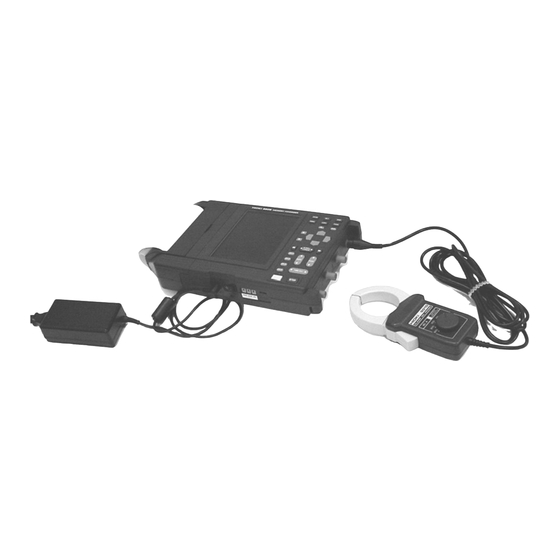
Power hicorder
Hide thumbs
Also See for 8715-01:
- Instruction manual (214 pages) ,
- Simple setup manual (4 pages) ,
- Simple setup manual (4 pages)

Related Manuals for Hioki 8715-01


Summary of Contents for Hioki 8715-01
- Page 1 MEASUREMENT GUIDEMEASUREMENT GUIDE For...は専用機種。複数の場合は「/」で区切る。不要の場合はとる。 形名を入力。 複数の場合は「/」で区切る。 8715-01 品名を入力。 POWER HiCORDER...
-
Page 2: Table Of Contents
Also, be sure to read the POWER HiCORDER's instruction manual for information on cautions to take when connecting the device and performing measurements. Make sure you fully understand the contents before operating the device. HIOKI cannot be held liable for any accidents except for those caused by the product. -
Page 3: Viewing The Voltage Waveform Of The 220 V Power Line
―――――――――――――――――――――――――――――――――――――――――――――――――――――――― Viewing the Voltage Waveform of the 220 V Power Line 9197 CONNECTION CORD 9418-15 AC ADAPTER To view the voltage waveform, set the measurement mode to "Waveform". For the time axis setting, "2ms" would be quite satisfactory. Set the recording length to "20 DIV". In the case of voltage waveform, after selecting "Volt"... -
Page 4: Viewing The Current Waveform Of The Power Line
―――――――――――――――――――――――――――――――――――――――――――――――――――――――― Viewing the Current Waveform of the Power Line 9418-15 AC ADAPTER 9010-10 CLAMP ON PROBE To view the current waveform, set the measurement mode to "Waveform". For the time axis setting, "2ms" would be quite satisfactory. Set the recording length to "20 DIV". In the case of current waveform, after selecting "clamp sensor"... -
Page 5: Recording The Passage Current Waveform
―――――――――――――――――――――――――――――――――――――――――――――――――――――――― Recording the Passage Current Waveform 9418-15 AC ADAPTER 9010-10 CLAMP ON PROBE To record the passage current waveform, set the measurement mode to "Waveform". For the time axis setting, "2ms" would be quite satisfactory. Set the recording length to "20 DIV". In the case of current waveform, after selecting "clamp sensor"... -
Page 6: Recording The Instantaneous Stop Waveform Of The 220 V Power Source
―――――――――――――――――――――――――――――――――――――――――――――――――――――――― Recording the Instantaneous Stop Waveform of the 220 V Power Source 9197 CONNECTION CORD 9418-15 AC ADAPTER To record the instantaneous stop waveform of the power source, set the measurement mode to "Waveform". For the time axis setting, "2ms" would be quite satisfactory. Set the recording length to "20 DIV". -
Page 7: Recording The Surge Current Waveform When Power Is Supplied
―――――――――――――――――――――――――――――――――――――――――――――――――――――――― Recording the Surge Current Waveform when Power is Supplied 9418-15 AC ADAPTER 9010-10 CLAMP ON PROBE To record the waveform of the surge current, set the measurement mode to "Waveform". For the time axis setting, "2ms" would be quite satisfactory. Set the recording length to "20 DIV". In the case of current waveform, after selecting "clamp sensor"... -
Page 8: Recording The Rms Value Of The Voltage Variation Of The 220V Power Source
―――――――――――――――――――――――――――――――――――――――――――――――――――――――― Recording the RMS Value of the Voltage Variation of the 220 V Power Source 9197 CONNECTION CORD 9418-15 AC ADAPTER To record the voltage variation of the power source, set the measurement mode to "Trend". For the time axis setting, initially setting it to "10s" would be easy to understand. For the measurement frequency, specify one which is suitable for the region you are located. -
Page 9: Recording The Rms Value Of The Load Variation Of The Power Source
―――――――――――――――――――――――――――――――――――――――――――――――――――――――― Recording the RMS value of the Load Variation of the Power Source 9418-15 AC ADAPTER 9010-10 CLAMP ON PROBE To record the load (current) variation of the power source, set the measurement mode to "Trend". For the time axis setting, initially setting it to "10s" would be easy to understand. For the measurement frequency, specify one which is suitable for the region you are located. -
Page 10: Monitoring The Leak Current Waveform
―――――――――――――――――――――――――――――――――――――――――――――――――――――――― Monitoring the Leak Current Waveform 9199 CONVERSION ADAPTER 9094 OUTPUT CORD 9418-15 AC ADAPTER 9445 AC ADAPTER 3283 CLAMP ON LEAK PROBE To record the leak current waveform, set the measurement mode to "Waveform". For the time axis setting, "2ms" would be quite satisfactory. Set the recording length to "20 DIV". In the case of leak current waveform, after selecting "3283"... -
Page 11: Recording The Rms Value Of The Leak Current
―――――――――――――――――――――――――――――――――――――――――――――――――――――――― Recording the RMS Value of the Leak Current 9199 CONVERSION ADAPTER 9094 OUTPUT CORD 9418-15 AC ADAPTER 9445 AC ADAPTER 3283 CLAMP ON LEAK PROBE To record the RMS value of the leak current variation, set the measurement mode to "Trend". For the time axis setting, initially setting it to "10s"... -
Page 12: Viewing The Waveform Of Power Surge/Noise At The 220 V Power Line
―――――――――――――――――――――――――――――――――――――――――――――――――――――――― Viewing the Waveform of Power Surge/Noise at the 220 V Power Line 9197 CONNECTION CORD 9418-15 AC ADAPTER To record the waveform of power surge/noise, set the measurement mode to "Waveform". For the time axis setting, "2ms" would be quite satisfactory. Set the recording length to "20 DIV". In the case of voltage waveform, after selecting "Volt"... - Page 13 ―――――――――――――――――――――――――――――――――――――――――――――――――――――――― Waveform Detection Trigger The waveform detection trigger function compares the measured signal with a pre-defined control waveform range, and triggers if the signal deviates from the control range voltage. The control range consists of a positive and negative amplitude offset from either a standard sine wave or the previous input cycle.
-
Page 14: Viewing The Voltage Waveform Of The 440 V Power Line
―――――――――――――――――――――――――――――――――――――――――――――――――――――――― Viewing the Voltage Waveform of the 440 V Power Line 9418-15 AC ADAPTER 9322 DIFFERENTIAL PROBE 9418-15 AC ADAPTER The voltage waveform of the 440 V power line can be measured by using the 9322 DIFFERENTIAL PROBE. Set the measurement mode to "Waveform". For the time axis setting, set it to "2ms". - Page 15 ―――――――――――――――――――――――――――――――――――――――――――――――――――――――― Recording the Abnormal Waveform while Recording the Power Variation (Instantaneous Waveform Recording) During the instantaneous waveform recording in the power variation mode, transient phenomenon which occurs during the actual value recording of the power variation (voltage or current) can be recorded at high speed using the waveform level.
-
Page 16: Recording The Abnormal Waveform While Recording The Power Variation (Instantaneous Waveform Recording)
―――――――――――――――――――――――――――――――――――――――――――――――――――――――― Displaying the instantaneous waveform Press the [STOP] key to end the measurement. If the instantaneous waveform recording is ON, then when you press the [DISP] key in the waveform display screen of the RMS Trend Measurement mode, the screen switches between RMS screen and MEM screen. -
Page 17: Application Examples On 220 V Line Power Monitoring
―――――――――――――――――――――――――――――――――――――――――――――――――――――――― Application Examples on 220 V Line Power Monitoring In this example, the 220 V line's voltage waveform, current waveform, and leak current waveform are monitored simultaneously; when abnormal situation arises they are measured at the same time. This example uses CH1 to measure the voltage waveform, CH2 the current waveform and CH3 the leak current waveform. -
Page 18: Viewing The Waveform Before The Trigger Point (Pre-Trigger)
―――――――――――――――――――――――――――――――――――――――――――――――――――――――― Viewing the Waveform before the Trigger Point (Pre-Trigger) The pre-trigger function serves to record the waveform not only after but also before triggering has occurred. In the Waveform measurement mode, using the recording start point as 0% and the recording end point as 100%, the trigger point can be specified in percent. - Page 19 All reasonable care has been taken in the production of this manual, but if you find any points which are unclear or in error, please contact your supplier or the Sales and Marketing International Department at HIOKI headquarters. In the interests of product development, the contents of this manual are subject to revision without prior notice.
- Page 20 HEAD OFFICE 81 Koizumi, Ueda, Nagano 386-1192, Japan TEL +81-268-28-0562 / FAX +81-268-28-0568 E-mail: os-com@hioki.co.jp URL http://www.hioki.com/ HIOKI USA CORPORATION 6 Corporate Drive, Cranbury, NJ 08512, USA TEL +1-609-409-9109 / FAX +1-609-409-9108 8714A983-02 07-11H Printed on recycled paper...
Need help?
Do you have a question about the 8715-01 and is the answer not in the manual?
Questions and answers