Table of Contents
Advertisement
Quick Links
Advertisement
Table of Contents

Related Manuals for Hioki 8855


Summary of Contents for Hioki 8855
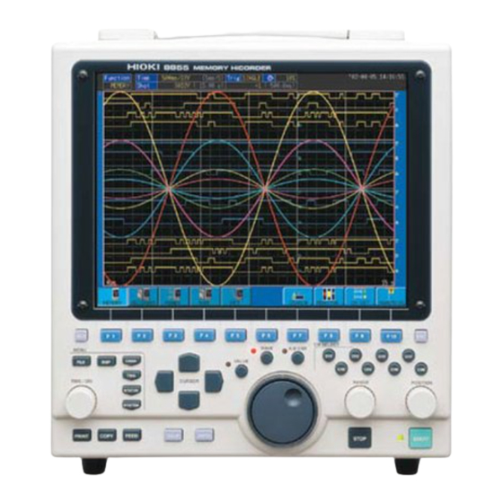
- Page 1 GUIDE BOOK 8855 MEMORY HiCORDER...
-
Page 2: About This Manual
The manual "Measurement Guide for the 8855" contains the minimum information necessary for operation of the 8855 MEMORY HiCORDER. For a detailed explanation of operating methods, please refer to the 8855 Quick Start Manual and 8855 Instruction Manual. Be sure to read and understand the sections entitled "Safety Notes"... -
Page 3: Identification Of Controls And Indicators
──────────────────────────────────────────────────── Identification of Controls and Indicators 10 11 12 13 14 15 16 Right Side Panel Power switch Switches on or off the power supply. AC connector The supplied power cord must be plugged in here. Function ground Connects to the earth. terminal (GND) External sampling Allows input of an external sampling clock. - Page 4 ──────────────────────────────────────────────────── SCSI connector An MO drive can be connected. LAN connector Can be connected to a network through a LAN. FD slot Floppy disk is inserted. MO slot MO disk is inserted. (when the 9646 is installed) Input unit slots These slots accept input units.
- Page 5 ──────────────────────────────────────────────────── Serve to select setting items. HELP Provides on-line help. CHAN Causes the display to show the Channel screen which serves for making input channel settings. DISP Causes the display to show measurement and analysis results. FILE Causes the display to show the File screen which serves for reading, storing, etc.
- Page 6 ──────────────────────────────────────────────────── Display Screen and Setting Screen Waveform display screen The screen shown below appears immediately after the power switch is turned on. The waveform display screen can also be displayed by pressing the red key. The following explains the DISP displayed items and the items that can be set in the waveform display screen.
- Page 7 ──────────────────────────────────────────────────── CH setting CH setting Input unit setting Trigger setting The following settings can The following settings can be entered for each be entered for each channel: channel. Display ON/OFF (Analog only) Voltage axis range Display ON/OFF (vertical axis) setting Trigger type setting Zero-position setting Trigger level setting...
-
Page 8: Channel Screen
──────────────────────────────────────────────────── Channel screen The channel screen can be displayed by pressing the key located on the left side of the CHAN unit. This screen is used to set units (analog input) and to enter logic input, display the settings for each channel, and to enter scaling settings, comments, and other detail settings. List Indicates the channel. - Page 9 ──────────────────────────────────────────────────── Options page Selection of the probe pressure- distribution ratio when the 9665, 9666, or 9322 is used Setting of the antialiasing filter (enabled when used with the 8953-10 unit) Setting of details (reference contact, burnout) for temperature measurement when used with the 8954 unit Setting of details (threshold, hold, level, etc.) when used with the 8955 unit In addition to the list page shown on the previous page, the channel screen includes the three...
-
Page 10: Trigger Screen
──────────────────────────────────────────────────── Trigger screen The trigger screen can be displayed by pressing the key located on the left side of the TRIG unit. This screen is used to set the trigger for each channel. To switch the page between analog and logic, press the Page Switch key ( function key). -
Page 11: Status Screen
──────────────────────────────────────────────────── Status screen The status screen can be displayed by pressing the key located on the left side of the STATUS unit. This screen is used to enter basic waveform data-acquisition settings, memory allocation settings, and calculation settings. STATUS Used to set the time axis (horizontal axis). The sampling speed changes automatically. -
Page 12: System Screen
The system screen is used to enter settings common to all functions; settings for printer, files, and communication; 8855 initial settings; and self-diagnosis settings. The following briefly describes each of these setting pages. SET UP (Refer to 9.2 "Set Up Screen" in the Quick Start Manual.) - Page 13 ──────────────────────────────────────────────────── INTERFACE (Refer to Chapter 11 "Communication Settings" in the Instruction Manual.) LAN settings FTP settings PC card settings (RS-232C, GP-IB, modem) PPP settings (transmission, reception, etc.) INITIALIZE (Refer to 9.5 "Initialize Screen" in the Quick Start Manual.) Clock setting Waveform data initialization System reset Menu control (display/hide setting)
-
Page 14: Setting Up The Main Unit
(Trigger mode: Continuous/Auto) pressed. To abort measurement, press the STOP key twice. Starting analysis Waveform zoom (Refer to Chapter 8 in the 8855 Quick Start Manual.) A-B cursors (Refer to Chapter 8 in the 8855 Quick Start Manual.) Begin analysis. - Page 15 ──────────────────────────────────────────────────── Simple measurement operations The following describes the simple operating procedures with a waveform input into Channel 1 (CH1) of the 8855 HiCORDER. (Example) Input of a sine wave of 1 kHz and 1 V, and observation of the waveform...
- Page 16 CH3: Connect the 3273 CLAMP ON PROBE to the 8951 VOLTAGE/CURRENT UNIT, and measure the current flowing in the equipment during instantaneous power interruption. Equipment 12 V 100 V 50 Hz 9198 3273 9198 8855 ──────────────────────────────────────────────────── Measurement Method...
- Page 17 ──────────────────────────────────────────────────── 3. Setup Display Setting item Setting Status screen Time axis (Time/Div) 20 ms/DIV Recording length (Shot) 30DIV Display mode (Format) Dual Channel screen Graph Mode Voltage Voltage 3273 Range 20 V Trigger screen Trigger mode Single Pre-trigger Kind Parameter Lower (limit): -100.00 V Upper (limit): 100.00 V Filt.
-
Page 18: Window Display
──────────────────────────────────────────────────── 2. Window display Move to "Format." (1) Separate the display of commercial power-supply waveforms from the display of other waveforms to prevent overlapping. Using the cursor keys, move the flashing cursor to "Format." Then, press the function key to set the "Format"... -
Page 19: Channel Setting
──────────────────────────────────────────────────── 3. Channel setting Move to "Range" or "Mode." Using the cursor keys, move the flashing cursor to "Range" or "Mode." Since CH1 receives a commercial 100-V power supply (approx. 141 Vp), press the function key to set the range (vertical axis) to " ."... - Page 20 ──────────────────────────────────────────────────── 4. Trigger setting The following describes the trigger condition setting method. To activate the trigger at the time of instantaneous power outage, use "Window In trigger." A commercial 100 V power supply has a sine waveform that ranges from -141 V to 141 V. In the following setting, the lower limit of the Window In trigger is set to "-100 V"...
- Page 21 ──────────────────────────────────────────────────── 5. Starting measurement (1) Press the DISP key to display the display screen. (2) Press the START key to begin measurement. Display the display screen. When an instantaneous power outage occurs, the trigger is activated and a waveform is acquired. Until then, the unit stands by.
- Page 22 2 V. The external amp also produces an output of 0 V at 0 G, and 2 V at 5 G. Subject board Acceleration sensor Impact 8855 (acceleration-sensor output amplifier) ──────────────────────────────────────────────────── Measurement Method...
- Page 23 ──────────────────────────────────────────────────── 3. Setup Display Setting item Setting Status screen Time axis (Time/Div) 1 ms/DIV Recording length (Shot) 1000DIV Channel screen Range CH1 200 mV Scaling CH1 In decimals (ENG) Setting method (Scaling Kind) CH1 Set with 2 points (POINT) Input P1 - Scale P1 CH1 [2.000] - [5.000] Input P2 - Scale P2 CH1 [-2.000] - [-5.000]...
- Page 24 ──────────────────────────────────────────────────── Display the channel screen. 2. Channel setting (1) Press the CHAN key to display the channel screen. (2) Make sure CH1 is selected. Using the cursor keys, move the flashing cursor to "Range." If CH1 is not Move to "Range," "Scaling," selected, press the F3 key to select CH1 before "Scaling kind,"...
-
Page 25: Trigger Setting
──────────────────────────────────────────────────── Display the trigger screen. 3. Trigger setting The following describes the procedure for setting trigger conditions. When there is a change from 0 V (0 G), the trigger is activated and waveform acquisition Move to "Kind," "Parameter," starts. "Trigger Mode," and "Pre-Trigger." (1) Press the TRIG key to display the trigger screen. - Page 26 ──────────────────────────────────────────────────── 5. Starting measurement Press the key to display the display screen. DISP Press the key to begin measurement. START Display the display screen. When the key is pressed, "Waiting for trigger" is START displayed at the upper right corner of the screen. When "Waiting for trigger"...
- Page 27 ──────────────────────────────────────────────────── 6. Analysis of waveforms (1) Waveform zoom Using the cursor keys, move the flashing cursor to the location shown in the diagram. Using the F1 or F2 function key, Display the display screen. magnify or compress the displayed waveform. To view the entire waveform on a single screen, press the F5 key.
- Page 28 ──────────────────────────────────────────────────── (3) A-B cursors A-B cursors are used to read frequency and numerical values such as maximum values. When the A.B CSR key is pressed, the red LED lights up and the GUI for A-B cursor settings appears. Select the type of cursor, ON/OFF of A-B cursors, and movement for reading a numerical value.
-
Page 29: External Memory Devices
The following memory devices and data recording methods can be used with the 8855. By selecting a device or method, data can be saved in the specified media. Data saved on any of these media in the 8855 recording format can be loaded into the 8855 for display and analysis. 1. Internal memory devices... - Page 30 ──────────────────────────────────────────────────── Selection of recording media (1) Press the FILE key. The file screen is displayed. (2) Press the media c hange F1 key. (3) Press the function key, and select a media for file saving and loading operations from among "FD," "PC CARD,"...
- Page 31 (for Excel). Data stored in text format Press the function key corresponding to the setting displayed in the screen. cannot be loaded into the 8855. (4) Specify a saving range. Move the flashing cursor to "Save Area," and specify the range of data to be saved.
- Page 32 F1 key to display the character input screen. Enter a file name. Regarding the input method, refer to "5.3.3 Character Entry Procedure" in the 8855 Instruction Manual. input Character input screen (6) Specify the method of processing to be executed if the entered file name already exists.
-
Page 33: Reading Measurement Data
Loads data while retaining waveform data for channels other than that used to read data Note Data saved in text format or BMP format cannot be loaded into the 8855. Only binary data saved by the 8855 can be loaded. F2 OVERWRITE REFRESH ────────────────────────────────────────────────────... - Page 34 ──────────────────────────────────────────────────── (4) Setting of a basic loading operation (for loading of settings files only) Move to the item to be set. Move the flashing cursor to "Basic Load," and select a loading method. None Does not load settings other than channel settings.
- Page 35 Automatic saving of measurement data After measurement, data can be automatically saved in a specified media. For details, see 9.3.1 "Setting the Auto Save Function" in the 8855 Quick Start Manual. Press several times to select (1) Press the SYSTEM key several times, and select "FILE SAVE."...
- Page 36 Measurement data can be continuously printed in real time. A measured waveform is automatically printed at the same time it is displayed on the screen. For details, refer to 9.4 "Printer Screen" and 9.4.3 "Real Time Print" in the 8855 Quick Start Manual. Press several times to select (1) Press the SYSTEM key several times and select "PRINTER."...
-
Page 37: Useful Information
──────────────────────────────────────────────────── Useful Information 1. About the function keys (1) Memory function Stores A/D-converted data in the memory for each sampling operation. Changing the time axis also alters the sampling frequency. (2) Recorder function The sampling frequency is fixed. Because changing the sampling frequency does not alter the time axis, measurement at a fast sampling speed is possible even with a slow time axis. - Page 38 6. About the screen display and DIV The 8855 is equipped with an SVGA (800 x 600) LCD. The waveform area uses 750 dots horizontally and 500 dots vertically. As there are 30 DIV horizontally and 20 DIV vertically, one grid (1 DIV) on the screen measures 25 dots horizontally and 25 dots vertically.
- Page 39 All reasonable care has been taken in the production of this manual, but if you find any points which are unclear or in error, please contact your supplier or the Sales and Marketing International Department at HIOKI headquarters. In the interests of product development, the contents of this manual are subject to revision without prior notice.
- Page 40 HEAD OFFICE 81 Koizumi, Ueda, Nagano 386-1192, Japan TEL +81-268-28-0562 / FAX +81-268-28-0568 E-mail: os-com@hioki.co.jp HIOKI USA CORPORATION 6 Corporate Drive, Cranbury, NJ 08512, USA TEL +1-609-409-9109 / FAX +1-609-409-9108 8855A983-00 02-07H Printed on recycled paper...
Need help?
Do you have a question about the 8855 and is the answer not in the manual?
Questions and answers