Sign In
Upload
Manuals
Brands
Hioki Manuals
Measuring Instruments
8835-01
Hioki 8835-01 Manuals
Manuals and User Guides for Hioki 8835-01. We have
1
Hioki 8835-01 manual available for free PDF download: Instruction Manual
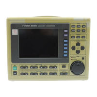
Hioki 8835-01 Instruction Manual (406 pages)
Memory HiCorder
Brand:
Hioki
| Category:
Measuring Instruments
| Size: 5 MB
Table of Contents
Table of Contents
3
Inspection
13
Introduction
13
Safety Notes
15
Notes on Use
17
Chapter Summary
21
Chapter 1 Product Overview
23
Major Features
23
Basic and Advanced Versions
26
Additional Features
26
Identification of Controls and Indicators
28
Chapter 2 Installation and Preparation
33
Installation of the Unit
34
Power Supply and Ground Connection
36
Power On/Off
40
Probe Connection
41
8936 ANALOG UNIT, 8938 FFT ANALOG UNIT and 8946 4 Ch ANALOG UNIT
41
8937 Voltage/Temp Unit
42
8939 Strain Unit
44
8940 F/V Unit
45
8947 Charge Unit
47
Logic Probe Connection
48
9322 DIFFERENTIAL PROBE Connection
49
Loading Recoding Paper
49
Storage and Handling Precautions
52
Notes on Measurement
53
Using a Voltage Transformer
55
Maximum Input Voltage
55
Chapter 3 Basic Operation and Measurement
57
Basic Operation
57
Basic Display Operation
57
Setting Items
58
JOG/SHUTTLE Control and Select Key
59
Measurement Start and End
60
Basic Input Operation
60
Printer Key Operation
61
Other Keys Operation
61
On-Line Help
63
Basic Measurement and Setting Procedures
64
Basic Operation Flow
64
Measuring and Recording a Voltage
65
(Memory Recorder Function)
65
(RMS Recorder Function)
69
Chapter 4 Memory Recorder Function
71
Outline
71
Outline of the Memory Recorder Function
71
Operation Sequence
72
Making Settings
73
Setting the Function Mode
73
Setting the Time Axis Range
74
Setting the Recording Length
75
Setting the Format
77
Using the X-Y Waveform Plots
79
Setting the Printer Format
81
Setting the Roll Mode
83
Setting the Auto Print Function
83
Setting the Auto Save Function
84
Overlay
86
Setting the Trigger
87
Input Channel Settings
87
Settings on the Display Screen
88
Automatic Setting of Time Axis and Voltage Axis
89
Summary of the Processing Functions
90
Processing Method
91
Waveform Parameter Calculation Details
93
Start and Stop Measurement Operation
97
Print Examples
98
Recorder Function
101
Chapter 5 Recorder Function
101
Outline
101
Outline of the Recorder Function
101
Operation Sequence
102
Making Settings
103
Setting the Function Mode
103
Setting the Time Axis Range and Sampling
104
Setting the Recording Length
106
Setting the Format
108
Setting the Printer Format
111
Setting the Additional Recording Function
113
Setting the Printer Function (Real Time Printing)
114
Setting the Auto Save Function
115
Setting the Trigger
116
Input Channel Settings
116
Settings on the Display Screen
117
Setting Compression Along the Time Axis
117
Start and Stop Measurement Operation
118
Print Examples
119
Chapter 6 RMS Recorder Function
121
Outline
121
Outline of the RMS Recorder Function
121
Operation Sequence
122
Making Settings
123
Setting the Function Mode
123
Setting the Time Axis Range
124
Setting the Frequency
125
Setting the Recording Length
126
Setting the Format
128
Setting the Printer Format
130
Setting the Additional Recording Function
132
Setting the Printer Function (Real Time Printing)
133
Setting the Auto Save Function
134
Setting the Trigger
135
Input Channel Settings
135
Settings on the Display Screen
136
Setting Compression Along the Time Axis
136
Start and Stop Measurement Operation
136
Print Examples
137
Chapter 7 Input Channel Settings
139
Overview
139
Selecting Channels (Memory Recorder Function Only)
139
Making the Settings of the 8936 ANALOG UNIT
140
Setting the Waveform Display Color
140
Setting the Waveform Display Graph Type
142
Setting the Voltage Axis Range
143
Setting the Input Coupling
144
Setting the Magnification/Compression Ratio Along the Voltage Axis
145
Setting the Zero Position
146
Zero Adjustment
148
Configuring Baseline Offset
149
Setting the Low-Pass Filter
151
Making the Settings of the 8937 VOLTAGE/TEMP UNIT
152
Setting Input for the VOLTAGE/TEMP UNIT
152
Making the Settings of Voltage Measurement
153
Making the Settings of Temperature Measurement
154
Making the Settings of the 8938 FFT ANALOG UNIT
157
Settings
157
Setting the Anti-Aliasing Filter (Advanced Version)
157
Making the Settings of the 8939 STRAIN UNIT
159
Setting the Waveform Display Color
159
Setting the Waveform Display Graph Type
159
Setting the Measurement Range
159
Auto-Balancing
160
Setting the Magnification/Compression Ratio Along the Measurement Range
161
Setting the Zero Position
162
Setting the Low-Pass Filter
162
Making the Settings of the 8940 F/V UNIT
163
Settings
163
Setting for Measuring Frequency
164
Setting Integral Measurement
168
Setting for Measuring Pulse Duty Ratio
170
Setting for Measuring Voltage
171
Setting for Measuring Current
172
Making the Settings of the 8946 4 Ch ANALOG UNIT
174
Settings
174
Setting the Input Coupling
175
Making the Settings of the 8947 CHARGE UNIT
176
Settings
176
Setting for Measuring Acceleration
177
Setting for Measuring Voltage
181
Making Logic Input Settings
182
Copying Channels
184
Arbitrary Setting of Voltage Axis Magnification/Compression and Display Range
185
Input Level Monitor Function
188
Channel Guide
190
Chapter 8 Trigger Functions
191
Overview
191
Setting the Trigger Mode
193
Setting the Pre-Trigger (Memory Recorder and RMS Recorder Functions)
194
Trigger Timing (Recorder Function)
197
Setting Trigger Source AND/OR Linking
198
Using the Analog Trigger Function
199
Level Trigger (RMS Recorder Function Excluded)
200
Window-In, Window-Out Trigger
204
(RMS Recorder Function Excluded)
204
Voltage Drop Trigger (Memory Recorder Function Only)
207
Period Trigger (RMS Recorder Function Excluded)
209
RMS Level Trigger (RMS Recorder Function Only)
213
Using the Logic Trigger Function
216
Using the Timer Trigger Function
218
Using the External Trigger Function
221
Manual Trigger
222
Trigger Output Connector
222
Chapter 9 SYSTEM Screen Settings
223
Overview
223
How to Use the SYSTEM Screen
224
Special Function Settings [ SETUP ]
225
Channel Selection (Memory Recorder Function)
226
Start Key Backup
226
Setting the Grid
227
Channel Marker Function
227
Displaying the Time from the Trigger Point
228
(Time Display)
228
List and Gauge Functions
228
Setting the Printer Density
229
Setting Backlight Saver Function
229
Setting the Display Colors
230
Setting the Beep Sound
231
Setting the Language
231
Setting PRINT/EXT.SMPL
232
Scaling Function [ SCALING ]
233
Conversion Ratio Scaling
234
2-Point Scaling
237
Unit Entry Procedure
241
Copy Settings
242
Scaling Setting Example
243
Adding Comments to a Graph [ COMMENT ]
244
Title Comment Input
245
Analog Channel Comment Input
246
Moving to the Analog Channel Comment Input Screen or the Logic Channel Comment Input Screen
247
Logic Channel Comment Input
248
Character Entry Procedure
249
Description of Window Contents
250
Interface Settings (Media Settings)
251
Setting the Output Destination by the COPY Key
252
Setting the Output Destination by the PRINT Key
253
GP-IB Interface Settings
254
RS-232C Interface Settings
255
Setting the LAN Interface
257
Initialization [ INITIALIZE ]
261
Setting the Clock [ TIME SET ]
261
Clear Waveform Data [ WAVE DATA CLEAR ]
262
System Reset [ SYSTEM RESET ]
263
Self Check
264
ROM/RAM Check
264
Printer Check
265
Display Check
265
Key Check
266
PC Card Check
266
Chapter 10 Printout of Waveform Data
267
Overview
267
Selecting Waveform or Numeric Print
268
Using the Smooth Print Function (Memory Recorder Function Only)
270
Setting the Grid
272
Channel Marker Function
272
Adding Comment to Printout
273
Printing Procedure
274
Manual Print (All Functions)
274
Auto Print (Memory Recorder)
275
Real-Time Print (Recorder, RMS Recorder)
276
Partial Print (All Functions)
277
Screen Hard Copy (All Functions)
278
List Print (All Functions)
278
Report Print (All Functions)
279
External Printer (Color Print)
280
Chapter 11 Using the A/B Cursors / Waveform Scrolling
281
Overview
281
Using the A/B Cursors
282
Line Cursor (Vertical, Horizontal) (All Functions)
282
Trace Cursor
282
Using the Cursors
283
Scrolling the Waveform
286
Zoom Function
287
Vernier Function
289
Key Lock Function
291
Chapter 12 External Input/Output Connectors /
291
Overview
291
External Start/Stop
292
External Printing/Sampling
294
Using the External Trigger Input (EXT TRIG)
295
Using the External Trigger Output (TRIG OUT)
296
Using the Evaluation Outputs (GO), (NG)
297
Using the Key Lock Function
298
Chapter 13 Storing, Retrieving and Deleting Waveform Data and Measurement Settings
299
Outline
299
Handling the Floppy Disk
300
Floppy Disk
300
Using the Floppy Disk Drive
301
Initializing (Formatting) the Floppy Disk
302
Handling the PC Card
303
PC Card
304
Using the PC Card Slot (PC Card with a Cable Only)
305
Storing, Retrieving and Deleting Data on the Floppy Disk or PC Card
308
Overview
308
FILE Screen
308
What Can be Recorded and How Much
308
Selecting the Media Type
309
Detailed Explanation of the Commands
310
Using a PC Card on a Personal Computer
325
Windows 95
325
Windows 3.1 and MS-DOS
325
Chapter 14 Specifications
327
General Specifications
327
Basic Specifications
327
Recorder
329
Display
329
External Data Storage
330
Interface
330
Others
331
Trigger Unit
332
Memory Recorder Function
333
Recorder Function
334
RMS Recorder Function
335
Recorder & Memory Function (Advanced Version)
336
FFT Function (Advanced Version)
337
Advanced Version
338
Auxiliary Function
338
Others
339
9439 DC POWER ADAPTER Specifications
340
System Operation
341
Chapter 15 Logic and Analog Inputs
345
Logic Inputs
345
Logic Probes
346
Analog Inputs
348
8936 Analog Unit
348
8937 Voltage/Temp Unit
349
8938 Fft Analog Unit
351
8939 Strain Unit
352
8940 F/V Unit
353
8946 4 Ch ANALOG UNIT
355
8947 Charge Unit
356
Replacement Procedure
358
Replacement Procedure
359
Input Cables
360
Connection Cable
360
9322 DIFFERENTIAL PROBE Connection
361
9018-10/9132-10 Clamp-On Probe
362
Measurement Errors Caused by Signal Source Internal Resistance
363
Troubleshooting
369
Advertisement
Advertisement
Related Products
Hioki 8715-01
Hioki 8841
Hioki 8842
Hioki 8870-20
Hioki 8730-10
Hioki 8731-10
Hioki 8846
Hioki 8847
Hioki 8808-01
Hioki 8807-01
Hioki Categories
Measuring Instruments
Test Equipment
Data Loggers
Multimeter
Accessories
More Hioki Manuals
Login
Sign In
OR
Sign in with Facebook
Sign in with Google
Upload manual
Upload from disk
Upload from URL