
Related Manuals for Dräger Polytron 3000


Summary of Contents for Dräger Polytron 3000
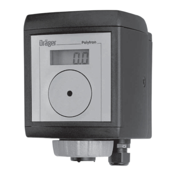
- Page 1 Dräger Polytron 3000 (approved as type P3S) Transmitter for electrochemical Sensors Instructions for Use...
-
Page 2: Table Of Contents
....10 Installing the measuring unit Dräger Polytron 3000 ......10 Fitting the sensor . -
Page 3: For Your Safety
For Your Safety For Your Safety Strictly follow the Instructions for Use Any use of the apparatus requires full understanding and strict observation of these instructions. The apparatus is only to be used for purposes specified here. Maintenance The unit must be inspected and serviced regularly by suitably qualified persons. Repair and general overhaul of the apparatus may only be carried out by trained serv- ice personnel. -
Page 4: Intended Use
For further details, see the installation notes. Notes on use in zone 22: Valid for all Dräger Polytron 3000 versions (see II 3D identification marking on the identification tag) and the accessories Duct Mount Kit (Order No. 8317150). Identification marking and safety data concerning dust explosion protection: II 3D, IP6x T65 C (–40... -
Page 5: Design
Polytron 3000 is designed for connection to the Dräger Polytron, Regard, QuadGard or Unigard central units. The Polytron 3000 transmitter may also be connected to other central units if the fol- lowing conditions are met: — Industrial standard 4 to 20 mA input signal —... -
Page 6: Installing The Transmitter
In explosion-hazard areas: Observe the national regulations concerning electrical equipment in explosion-hazard areas. The Dräger Polytron 3000 transmitter consists of two main components: — Dräger docking station This can be pre-installed anywhere and contains the electrical installation compo- nents. -
Page 7: Installing The Docking Station
Installing the transmitter Installing the docking station — If the transmitter is to be installed in a Zone 2 explosion-hazard area, select a lo- cation with low exposure to mechanical risk. — Docking station is installed vertically (transmitter with sensor facing down) in an area with low vibrations and stable temperatures –... -
Page 8: How To Install The Electrical Connections
Shorten the shield (if installed) to prevent short-circuiting: ● Connect cable 1 2-pin terminal for Polytron 3000 – check polarity (marking in the docking station). Cut excess wires short or 2 Fasten in 4-pin terminal. 1 Slide connecting terminal back into holder. -
Page 9: Installing The Transmitter In Areas Subject To Explosion Hazards Of Zone 0 Or Zone 1
Installing the transmitter Installing the transmitter in areas subject to explosion hazards of zone 0 or zone 1 ● Install a safety barrier with the appropriate explosion protection approval (catego- ry 1, 2 or Div. 1) between the transmitter and the control unit. ) ≤... -
Page 10: Installing The Transmitters In Non-Explosion-Hazard Areas
4 ... 20 mA – Control unit +24 V 4 to 20 mA Installing the measuring unit Dräger Polytron 3000 ● Remove the rain cover from the previously installed docking station. ● Examine seal for signs of dirt and clean if necessary. -
Page 11: Fitting The Sensor
2 Open the front cover of the service port with an Allen key by turning anticlockwise (approx. 60 Attention: Polytron Use only a 5 mm Allen key without a ball head. 3 Only use the DrägerSensor specified on the sticker on the Polytron 3000 meas- uring unit. ● Remove sensor from packaging. ●... -
Page 12: Start-Up
— A current between 4 and 20 mA flows through the transmitter during normal op- eration. This current is proportional to the gas concentration. — Polytron 3000 uses various current values to indicate the operating status of the transmitter: Current... -
Page 13: Maintenance
Maintenance Maintenance Maintenance intervals Before starting operation: ● Check the calibration, see page 14. ● Check the transmission of signals to the control unit and the triggering of alarms. At regular intervals, to be defined by the person responsible for the gas warning installation: ●... -
Page 14: Unit Calibration
Attention! Use only a 5 mm Allen key without a ball head. Note: The Dräger Polytron 3000 does not support the storage of calibration data in the sensor data base. Measuring / maintenance mode 1 Maintenance switch with two positions. - Page 15 Maintenance Output for calibration 4 Connect voltmeter (mV setting, Ri > 10 M) to test points TP1 and TP2 (required for the version without display). Caution: – — For operation in explosion-hazard areas: Only use intrinsically safe voltmeters with electrical parameters to the fol- lowing specifications: ) 7.6 V;...
-
Page 16: Calibrating The Zero Point
Maintenance Calibrating the zero point For all sensors except oxygen sensor: The zero point can be calibrated without the use of nitrogen (zero gas) when the ambient air is free from measuring gas and other interfering gases. Alternatively: Polytron 1 Use the calibration adapter. ●... -
Page 17: Replacing The Sensor
Allen key (approx. 60 Replacing the sensor The sensor can be replaced, if necessary, without interrupting the power supply in the explosion-hazard area. Use only DrägerSensors which are approved for use with the Dräger Polytron 3000 transmitter. Polytron Caution: —... - Page 18 Maintenance 1 Set maintenance switch to left-hand position. The 4 to 20 mA output changes to measuring mode. ● Refit the front cover of the service port and lock it in place by turning clockwise with an Allen key (approx. 60 Polytron When the sensor has warmed up: —...
-
Page 19: Fault - Cause - Remedy
Fault – Cause – Remedy Fault – Cause – Remedy Fault Cause Remedy Flashing display Sensor warms up Wait for warm-up phase to end. Display Equipment fault, Only use a sensor with the gas type, Part No. e.g. wrong sensor installed and measuring range indicated on the sticker. -
Page 20: Technical Data
— Electromagnetic compatibility (Directive 89/336/EEC) max. influence on sensor: 2 x repeatability Ingress protection IP 66 / IP 67, according to EN 60 529 / IEC 529 (NEMA 4) Approvals Polytron 3000 is certified as type P3S. ATEX Device markings in accordance with 94/9/EC II 1G 0158 EEx ia IIC T4 (–40... - Page 21 Technical Data UL (Underwriters Laboratories Inc.) Only as to Intrinsic Safety for use in Hazardous Locations Class I, Div. 1, Groups A, B, C, D Class II, Div. 1, Groups E, F, G Use in accordance with Dräger Control Drawing SE20105. T4: –40 ≤...
-
Page 22: Order List
Order List Order List Part name and description Order No. Dräger Docking Station 83 17 990 Polytron 3000 measuring units and DrägerSensors Overview, page 23 and page 25 Accessories: Splash guard 68 07 549 Splash guard AC sensor 68 09 379... -
Page 23: Polytron 3000 Measuring Units
Order List Polytron 3000 measuring units Part name and description Order No. Order No. Order No. with display without display DrägerSensor For measuring ammonia (NH Polytron 3000 measuring unit, 83 16 637 83 16 737 68 09 680 Measuring range 0 to 100 ppm NH , for DrägerSensor NH... - Page 24 Order No. Order No. with display without display DrägerSensor For measuring oxygen (O Polytron 3000 measuring unit, 83 16 642 83 16 742 68 09 720 Measuring range 0 to 5 Vol.-% O , for DrägerSensor O2 Polytron 3000 measuring unit,...
- Page 25 Order No. Order No. with display without display DrägerSensor For the measurement of hydrogen (H Polytron 3000 measuring unit, 83 16 669 83 16 769 68 09 685 Measuring range 0 to 1000 ppm, for DrägerSensor H Polytron 3000 measuring unit,...
-
Page 26: Atex Approval
ATEX approval ATEX approval... - Page 27 ATEX approval...
- Page 28 ATEX approval...
- Page 29 ATEX approval...
- Page 30 ATEX approval...
-
Page 31: Iecex Approval
IECEx approval IECEx approval... - Page 32 IECEx approval...
- Page 33 IECEx approval...
- Page 34 IECEx approval...
-
Page 35: Ul Approval
UL approval UL approval... - Page 36 UL approval...
- Page 37 UL approval...
-
Page 38: Csa - Approval
CSA - Approval CSA - Approval... - Page 39 CSA - Approval...
- Page 40 CSA - Approval...
- Page 41 CSA - Approval...
- Page 42 CSA - Approval...
-
Page 43: Declaration Of Conformity
Declaration of Conformity Declaration of Conformity... - Page 44 Declaration of Conformity...
- Page 45 Declaration of Conformity...
- Page 46 Declaration of Conformity...
-
Page 47: Index
Index Index 4 to 20 mA current loop ..........8 Accessories . - Page 48 Index Ingress protection ........... . 20 Inspection .
- Page 49 The measuring unit Dräger Polytron 3000 ....... . . 6...
- Page 50 Index...
-
Page 51: Drilling Templates
Drilling templates Drilling templates Dräger docking station... - Page 52 Dräger Safety AG & Co. KGaA Revalstraße 1 D-23560 Lübeck Germany Tel. +49 451 8 82 - 27 94 Fax +49 451 8 82 - 49 91 www.draeger.com 90 33 020 - GA 4684.200 en © Dräger Safety AG & Co. KGaA edition - 06_2007 Subject to alteration...
Need help?
Do you have a question about the Polytron 3000 and is the answer not in the manual?
Questions and answers