Subscribe to Our Youtube Channel
Summary of Contents for Patton electronics 1180
-
Page 1: User Manual
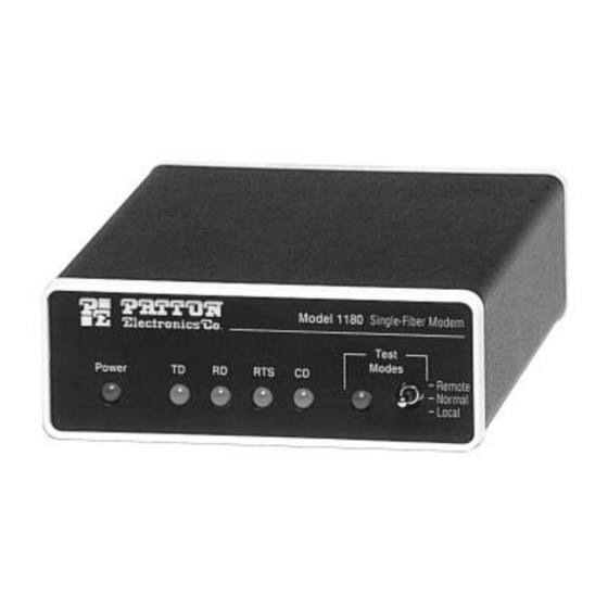
USER MANUAL MODEL 1180 Single Fiber Short Range Modem SALES OFFICE Part# 07M1180-B Doc# 017071UB (301) 975-1000 Revised 1/5/96 TECHNICAL SUPPORT (301) 975-1007... - Page 2 The Model 1180 features extended data rate circuitry that allows for single fiber distances between 2.5 and 5 Km. Optical fiber may be connected to the Model 1180 using an ST or SMA type interface. The Model 1180 encodes the electrical signal using 3B4B modulation. The electrical signal is then converted to an optical signal and transmitted using an 880 nm light emitting diode.
-
Page 3: Detailed Switch Settings
3.0 CONFIGURATION The Model 1180 uses a set of eight external DIP switches that allow configuration to a wide range of applications. Because all eight switches are in one externally accessible DIP package, there is no need to open the Model 1180’s case for configuration. The switches allow you to control data rates and clocking methods. - Page 4 Switch 2 Switch 3 Switch 4 Switch 5 Data Rate Switch 6: Reset Switch 6 lets you reset the Model 1180 without powering down the unit. The default position of the switch allows normal operation. Switch 6 Reset Condition Operating Condition...
-
Page 5: Installation
2.5 or 5 Km long. The fiber cable connects to each Model 1180 using either an ST or an SMA connector. Figure 5 shows a close up of both connector types. - Page 6 5.2 POWER-UP / SYNCHRONIZATION Apply AC power to the Model 1180 by plugging the separate AC power adapter first into the rear panel outlet of the Model 1180 and then into an acceptable AC power outlet. There is no power switch on the Model 1180: When the “power”...
-
Page 7: Remote Loopback
The remote loopback test checks the performance of both the local and remote Model 1180s, and the communication link between them (Figure 7). Any characters sent to the remote Model 1180 in this test mode will be returned back to the originating device. For example,... -
Page 8: Troubleshooting
Remove the cord from defective the outlet and check for continuity AC transformer is not Plug transformer into plugged into the Model Model 1180 1180 If CD is low, possible Check for ongoing Carrier Detect (CD) synchronization loss power loss or break in... -
Page 9: Appendix Bspecifications
APPENDIX C RS-232 INTERFACE STANDARD DIRECTION STANDARD “DCE” SETTING 1- (FG) Frame Ground 2- (TD) Transmit Data From Model 1180 Transmitting Timing - 15 3- (RD) Receive Data 4- (RTS) Request to Send From Model 1180 Receiver Timing - 17...


Need help?
Do you have a question about the 1180 and is the answer not in the manual?
Questions and answers