Table of Contents
Advertisement
Quick Links
Advertisement
Table of Contents

Summary of Contents for Patton electronics 1186
- Page 1 USER MANUAL MODEL 1186 Multi-Mode Fiber Modem with Fixed G.703/G.704 Interface Part# 07M1186-UM SALES OFFICE Doc# 01716U2-001, (301)975-1000 Rev. C TECHNICAL SUPPORT Revised 10/25/06 C E R T I F I E D (301)975-1007 An ISO-9001 http://www.patton.com Certified Company...
-
Page 2: Radio And Tv Interference
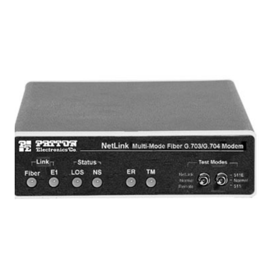
However, there is no guarantee that interfer- ence will not occur in a particular installation. If the Model 1186 does cause interference to radio or television reception, which can be deter-... - Page 3 V.52 compliant 511/511E test patterns. Front panel switches activate test patterns and loopbacks. LED status indicators monitor the fiber and G.703/G.704 links. The Model 1186 is available with an AC or DC power supply and is supported by a wide range of applications and power supply environments.
- Page 4 Note: The Model 1186 units are intended to work in pairs. When setting the clock modes for the Model 1186 units, one end of the link must be set for Receive Recover and the other end must be set for either Internal or Network.
- Page 5 Figure 4 below shows the top view of the printed circuit board (PCB) and the location of the jumpers. Figure 4: Top view of 1186 circuit board and location of jumpers Open the Case To open the case, insert a screwdriver into the slots and twist the screwdriver head slightly.
-
Page 6: Connect The Fiber Interface
G.703/G.704 equipment, and to the power source. This section describes how to make these connections. The power, G.703/G.704 and Fiber Line connections are located on the rear panel of the Model 1186. Figure 5, below, shows the loca- tion of each of these ports. G.703/G.704 Figure 5. -
Page 7: Power Connection
(center pin is +5V). The universal input power supply has a male IEC-320 power entry connector. This power supply con- nects to the Model 1186 by means of a barrel jack on the rear panel. Many international power cords are available for the universal power supply (Please refer to Appendix B for country-specific power cords). -
Page 8: Test Modes
Network and a local connection. Any data sent to the local Model 1186 in this test mode will be echoed (returned) back to the user (see Figure 11). If two Model 1186 units are linked when the LAL is activated, data sent from the remote modem will also be looped back to the remote terminal equipment. - Page 9 Loopbacks, follow these instructions: 1. Locate the "511/511E" toggle switch on the front panel of the Model 1186 and move it UP. This activates the V.52 BER test mode and transmits a "511" test pattern into the loop. If any errors are present, the local modem's red "ER"...
-
Page 10: Specifications
A A P P P P E E N N D D I I X X A A PATTON ELECTRONICS MULTI-MODE FIBER MODEM WITH G.703/G.704 FIBER INTERFACE SPECIFICATIONS Clocking Modes: Network (G.703/G.704), Internal, Receive Recover Line Rate: 2048 kbps Diagnostics: V.52 compliant (511/511E) pattern generator and detector with error injection mode. - Page 11 PATTON ELECTRONICS MODEL 1186 FACTORY REPLACEMENT PARTS AND ACCESSORIES Patton Electronics Model # Description 1186 ...multi-mode fiber optic modem 1186RC...multi-mode fiber rack card modem 48V-PSM ...DC Power Supply Module 08055DCUI ...100-240VAC (+5V ±5% reg. DC/2A) Universal Input Adapter 0805EUR ...European Power Cord CEE 7 (“A”) 0805UK ...United Kingdom Power Cord (“D”)


Need help?
Do you have a question about the 1186 and is the answer not in the manual?
Questions and answers