Table of Contents
Advertisement
Quick Links
Download this manual
See also:
User Manual
Advertisement
Table of Contents

Related Manuals for JAI BM-500GE


Summary of Contents for JAI BM-500GE
- Page 1 User's Manual BM-500 GE BB-500 GE Digital Monochrome / Color Progressive Scan GigE Vision Camera Document Version: 1.3 BMB-500GE_Ver.1.3_May2010...
- Page 2 JAI Ltd., Japan and may only be used by the purchasers of the product. JAI Ltd., Japan makes no warranty for the use of its product and assumes no responsibility for any errors which may appear or for damages resulting from the use of the information contained herein.
- Page 3 BM-500GE Supplement The following statement is related to the regulation on “ Measures for the Administration of the control of Pollution by Electronic Information Products “ , known as “ China RoHS “. The table shows contained Hazardous Substances in this camera.
- Page 4 BB-500GE Supplement The following statement is related to the regulation on “ Measures for the Administration of the control of Pollution by Electronic Information Products “ , known as “ China RoHS “. The table shows contained Hazardous Substances in this camera. mark shows that the environment-friendly use period of contained Hazardous Substances is 15 years.
-
Page 5: Table Of Contents
6.5.2 Internal Trigger Generator................17 GigE Vision Streaming Protocol (GVSP) ............18 Digital Video Output (Bit Allocation) ..............18 Bit Allocation (Pixel Format / Pixel Type) – BM-500GE (monochrome) ......18 7.2.1 GVSP_PIX_MONO8 (8bit) ................18 7.2.2 GVSP_PIX_MONO10 (10bit) ................18 7.2.3 GVSP_PIX_MONO10_PACKED ( 10 bit ) .............. - Page 6 BM-500GE / BB-500GE Basic functions ....................28 8.3.1 Vertical Binning (BM-500GE only)..............28 8.3.2 BB-500GE. Bayer mosaic filter ..............29 8.3.3 Partial Scanning ( Fixed rate and variable) ............29 8.3.4 Decimation Readout (Draft )mode (BB-500GE only) ..........29 8.3.5 Electronic Shutter ..................
-
Page 7: General
This manual covers the digital monochrome progressive scan camera BM-500GE and color progressive scan camera BB-500GE Part of the C3 Basic family, the BM-500GE/BB-500GE is a GigE Vision compliant camera. Both the monochrome version BM-500GE and the color version BB-500GE provide a frame rate of 15 frames/second at full resolution. -
Page 8: Main Features
15 frames/second with full resolution in continuous operation 15 frames/second with external trigger and full resolution Increased frame rate with vertical binning (BM-500GE only) , draft mode (BB-500GE only) and partial scan Exposure time from 64μs to 2 sec. using Pulse Width trigger mode ... -
Page 9: Locations And Functions
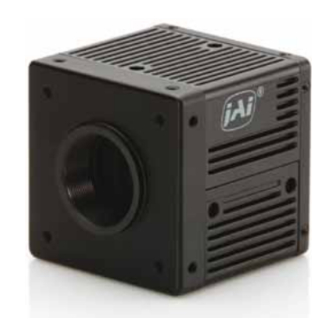
BM-500GE / BB-500GE 4. Locations and Functions ④ ③ D CIN/ T R IG P O W E R/ TR IG ⑩ ⑥ LINK A C T. ⑦ G igE ⑤ ⑧ ⑨ ② ① Lens mount C-mount (Note *1) ... -
Page 10: Pin Assignment
BM-500GE / BB-500GE 5. Pin Assignment 5.1 12-pin Multi-connector (DC-in/GPIO/Iris Video) Type: HR10A-10R-12PB (Hirose) male. Pin no. Signal Remarks (Seen from the rear of camera) +12 V DC input Opt IN 2 (-) / GND (*1) Opt IN 2 (+)/Iris Video out (*1) -
Page 11: Internal Dip Switch
BM-500GE / BB-500GE 5.4 Internal DIP switch In order to change, the top cover must be removed. SW601 For selection of OPT IN and SW600 For selection of TTL IN 1 75 Iris Video OUT ohm ON or OFF Factory default is UP position(OPT IN). -
Page 12: Gpio (Inputs And Outputs)
Outputs from LUT described in the blue line block shows GPIO settings for LINE SELECTOR on JAI Camera Control tool and inputs for LUT on the left side shows GPIO settings for LINE SOURCE on JAI Camera Control tool right. -
Page 13: 12-Bit Counter
1 through 4096, allowing a wide range of clock frequencies to be programmed. Setting Value 0 is bypass, setting value 1 is 1/2 dividing and setting value 4095 is 1/4096 dividing. The pixel clock for BM-500GE/BB-500GE is 60 MHz. 6.1.3 Pulse Generators (0 to 1) Each pulse generator consists of a 19-bit counter. -
Page 14: Recommended External Output Circuit Diagram For Customer
BM-500GE / BB-500GE 6.2.2 Recommended External Output circuit diagram for customer Fig.6. External Output Circuit, OPT OUT 1 and 2 6.2.3 Optical Interface Specifications The relation of the Input signal and the output signal through optical interface is as follows. -
Page 15: Inputs And Outputs Table
BM-500GE / BB-500GE 6.3. Inputs and outputs table Output Ports GPIO Port GPIO Port GPIO Port GPIO Port Camera Camera Time Stamp Sequence Pulse Pulse Trigger 0 Trigger 1 (OPT (OPT (TTL Reset Reset Generator 0 Generator 1 (TTL OUT2) -
Page 16: 12Bit Counter
BM-500GE / BB-500GE The following shows JAI SDK Camera Control Tool for setting. Line Selector Line Source Line Polarity 6.4.2 12bit counter Internal Name GenIcam Name Size Value (Range) Address Access 0x000: Bypass 0x001: 1/2 Dividing 0xB004 Counter Dividing Value... -
Page 17: Pulse Generators (19 Bit X 2)
1/25KHz = 40µs Start Point = 0 End Point = 100 Pulse Generator 0 (GPIO Port 1 ) Repeat counter: 0 to 255 Length = 102 =0: Continuously repeated The following shows JAI SDK Camera Control Tool for setting Pulse Generator. - Page 18 BM-500GE / BB-500GE Internal Name GenIcam name Size Value (range) Address Access Pulse Generator 0xB008 Length Counter 0 0x00001 to 0xFFFFF Length PulseGenerator 0xB00C Start point Counter 0(1) 0x00000 to 0xFFFFF StartPoint 0x00: infinite PulseGenerator 0x01: 1 time 0xB010 Start point Counter 0(2)
-
Page 19: Gpio Programming Examples
BM-500GE / BB-500GE 6.5. GPIO programming examples 6.5.1 GPIO Plus PWC shutter Example: 10µs unit pulse width exposure control (PWC). Pixel clock is 60MHz. 600 clocks (700-100) equal 10µs. Address Register Value 0xA040 Trigger Mode 2 = PWC (Pulse Width Control) -
Page 20: Internal Trigger Generator
BM-500GE / BB-500GE 6.5.2 Internal Trigger Generator Example: Create a trigger signal and trigger the camera Address Register Value 0xA040 Trigger Mode 1 = EPS 0xB000 Clock Choice 1 = Pixel Clock 0xB004 Counter Dividing Value 2079 = 1/2080 dev(Line... -
Page 21: Gige Vision Streaming Protocol (Gvsp)
7. GigE Vision Streaming Protocol (GVSP) 7.1 Digital Video Output (Bit Allocation) Although the BM-500GE and BB-500GE are digital cameras, the image is generated by an analog component, the CCD sensor. The table and diagram below show the relationship between the analog CCD output level and the digital output. -
Page 22: Gvsp_Pix_Mono10_Packed ( 10 Bit )
BM-500GE / BB-500GE 7.2.3 GVSP_PIX_MONO10_PACKED ( 10 bit ) 2 3 4 5 6 7 8 9 0 1 X X 0 1 X X 2 3 4 5 6 7 8 9 2 3 4 5 6 7 8 9 0 1 X X 0 1 X X 2 3 4 5 6 7 8 9 7.2.4 GVSP_PIX_MONO12 ( 12 bit ) -
Page 23: Gvsp_Pix_Bayrg12 " Bayer Rg12
BM-500GE / BB-500GE 7.3.3 GVSP_PIX_BAYRG12 “ Bayer RG12” Odd Line 0 1 2 3 4 5 6 7 8 9 10 11 X X X X 0 1 2 3 4 5 6 7 8 9 10 11 X X X X... -
Page 24: Functions And Operations
(NICs) and Switches/Routers are suitable for use with the GigE Vision compliant camera. JAI will endeavor to continuously verify these combinations, in order to give users the widest choice of GigE components for their system design. -
Page 25: Video Data Rate (Network Bandwidth)
In case using Jumbo Frame, the packet data will be improved 2 %. For BM-500GE and BB-500GE, the jumbo frame can be set at maximum 4036 Bytes (Factory setting is 1428 Byte). To set Jumbo Frame, refer chapter 8.2.4. -
Page 26: Enabling Jumbo Frame
BM-500GE / BB-500GE 8.2.4 Enabling Jumbo Frame (1) Click [Start] and click [Control Panel]. (2) Click [Performance and Maintenance]. (3) Click [System]. (4) Click [Hardware] tab. (5) Click [Device Manager]. (6) Expand [Network adapters]. (7) Select target NIC, right-click, and click [Properties]. - Page 27 BM-500GE / BB-500GE (8)Click [Advanced] tab. (9) Select Jumbo Frames of Property, and select 9014 of Value. (10)Click [OK]. (11)Close [Device Manager]. (12)Close [System Properties] clicking [OK].
-
Page 28: Setting Receive Descriptors
BM-500GE / BB-500GE 8.2.5 Setting Receive Descriptors If the Network Connection Properties list contains a property called Receive Descriptors, then change its property to the maximum value supported by the NIC installed in the computer. Click “OK“ to save the property. -
Page 29: Calculating And Setting Inter-Packet Delay
Packet Packet Duration of the entire packet, with delay JAI Control Tool has a built in wizard for calculating Inter-Packet Delay. When the Inter-Packet Delay function is activated, a button appears on the right hand side of the bar. Click the button to op-en the calculation wizard window. -
Page 30: Confirm The Filter Driver Is Used
The filter driver is installed as an optional function when JAI SDK is installed. If the filter driver is not installed at that time, it can be installed , All Programs ⇒ JAI SDK ⇒ GigE Vision Filter Driver ⇒... -
Page 31: Others
8.3 Basic functions The BM-500GE and BB-500GE cameras are progressive scan cameras with 12, 10 or 8-bit video output in Gigabit Ethernet. The camera has 1/2, 1/4 or 1/8 partial scanning for faster frame rates. -
Page 32: Bb-500Ge. Bayer Mosaic Filter
The partial scanning function uses the middle of the image vertically to achieve faster frame rate. This is effective for capturing and inspecting the image which does not require the height. BM-500GE/BB-500GE has 4 types of partial scan modes such as 2/3, 1/2, 1/4 an 1/8. Mode... -
Page 33: Electronic Shutter
4 lines readout out of 16 lines V out Fig.12. Draft mode 8.3.5 Electronic Shutter BM-500GE / BB-500GE have conventional shutter functions as well as the GenICam standard “Exposure Time Abs” function. Preset Shutter 10 steps preset shutter are available: OFF (1/15);... -
Page 34: Auto-Iris Lens Video Output (12-Pin Hirose Connector)
BM-500GE / BB-500GE Exposure Time Abs (GenICam Standard) This is a function specified in the GenICam standard. The shutter speed can be entered as an absolute exposure time in microseconds (μs) in register address 0xA018. The entered absolute time (Time Abs) is then converted to programmable exposure (PE) value inside the camera. -
Page 35: Auto-Detect Lval-Sync / A-Sync. Accumulation
BM-500GE / BB-500GE 8.3.7 Auto-detect LVAL-sync / a-sync. accumulation This function replaces the manual setting found in older JAI cameras. Whether accumulation is synchronous or a-synchronous in relationship to LVAL depends on the timing of the trigger input. When trigger is received while FVAL is high (during readout), the camera works in LVAL- synchronous mode, preventing reset feed trough in the video signal. -
Page 36: Bayer White Balance ( Register 0Xa0D0)
In order to offload the host, the BB-500GE can adjust Gr, R, Gb and B levels individually to get the white balance for the Bayer output signal. The gain is fixed to 1.0 for BM-500GE. Note: Bayer white balance must be set at Normal mode. - Page 37 BM-500GE / BB-500GE GigE Interface Video Process CCD Out Pixel format 14-bit 8-bit, 10-bit, 12-bit LUT Value (Coefficent) (X4.0) 16384 (X3.0) 8192 (X2.0) (X1.0) 4096 (X0.5) 2048 (X0.25) 1024 Video Inout LUT Index (D000 to D3FC) Gamma=0.45 (OFF) Look Up Table γ=0.45 setting Video IN/OUT γ=0.45 characteristics...
-
Page 38: Blemish Compensation Circuit
Bayer color pixels on both columns. The numbers of compensation is up to 8 pixels on both L and R channels. The circuit built in BM-500GE/BB-500GE is ON/OFF function for the compensated data in the factory. -
Page 39: Sensor Layout And Timing
BM-500GE / BB-500GE 8.5. Sensor Layout and timing 8.5.1 CCD Sensor Layout The CCD sensor layout with respect to pixels and lines used in the timing and video full frame read out is shown below. Active Pixel Output 2058 2456(H) x 2058(V) -
Page 40: Horizontal Timing
BM-500GE / BB-500GE 8.5.2 Horizontal timing The LVAL period is shown for normal continuous mode. FULL FRAME READ OUT / PATIAL READ OUT Fig. 20 Horizontal timing 8.5.3 Vertical timing The FVAL period for normal continuous mode full scan is shown. -
Page 41: Partial Scanning
BM-500GE / BB-500GE 8.5.4 Partial Scanning The FVAL period is shown for 1/2 partial scan in normal continuous mode. Vertical Timing The below diagram and table provide vertical timing information for the fixed partial scan settings 1/2, 1/4, 1/3 and 2/3. -
Page 42: Vertical Binning
By activating this function, the frame rate is increased to 44.492 fps. This function is available only for BM-500GE. Important Note Vertical Binning can not be used together with the Partial Scanning. -
Page 43: Operation Modes
BM-500GE / BB-500GE Vertical timing Fig.25 Vertical Timing for Vertical Binning 8.6. Operation Modes This camera can operate in 5 primary modes. 1. Continuous Mode Pre-selected exposure. 2. Pre-select Mode (PS) Pre-selected exposure. 3. Pulse Width Mode (PW) Pulse width controlled exposure. -
Page 44: Pre-Select Trigger Mode
For timing details, refer to fig. 18. through fig. 25. To use this mode: Set function: Trigger mode Scanning Full, Partial Vertical binning ON / OFF (BM-500GE only) Draft Mode ON / OFF (BB-500GE only) Shutter mode Preset, Programmable, Exposure Time Abs Shutter speed 1/30 to 1/10000... -
Page 45: Pulse Width Trigger Mode
For timing details, refer to fig. 18. through fig. 23 and fig. 26 and 27. To use this mode: Set function: Trigger mode Scanning Full, Partial Vertical binning ON / OFF(BM-500GE only) Draft Mode ON / OFF(BB-500GE only) Accumulation LVAL sync / LVAL a-sync Other functions and settings Input: Ext. - Page 46 BM-500GE / BB-500GE LVAL_sync timing Trig 2 L(Min.) LVAL 1L to 2L 1L(Max) CCD Exposure Exposure FVAL Trigger input whthin FVAL HIGH Period LVAL SYNC Mode Setting Fig. 28 Pulse width control LVAL sync. LVAL_async timing 5.37 μs ± 1 μs Trig 2 L(Min.)
-
Page 47: Sequential Trigger Mode (Ps)
BM-500GE / BB-500GE 8.6.4 Sequential Trigger Mode (PS) The ROI, Shutter and Gain values can be preset up to 10 sequences. Along with every trigger input, the image data with the preset sequence is output as described below. Trigger Sequence... -
Page 48: Delayed Readout Mode (Ps, Pw)
BM-500GE / BB-500GE The following table shows the minimum trigger interval in synchronous accumulation mode. In case of a-synchronous accumulation mode, the exposure time should be added to figures in this table. Full Scan 2/3 Partial 1/2 Partial 1/4 Partial... -
Page 49: Optical Black Transfer Mode
BM-500GE / BB-500GE 8.6.6 Optical Black transfer Mode It is possible for the user to decide whether the optical black (OB) portion of the image will be transferred or not. The optical black part can be used for black reference in the application software. -
Page 50: Multi Roi Mode (Multi Region Of Interest)
0x09 Pre-select Async (PS) 0x11 Delayed Auto Readout Note 1: Write ID in register address 0xA040 in order to set trigger mode. Note 2: Vertical Binning is available for only BM-500GE. Note 3: Draft mode is available only in BB-500GE. -
Page 51: External Appearance And Dimensions
BM-500GE / BB-500GE Note 4: The Auto iris output is only effective on Normal scan and Vertical binning modes. It is not available on the partial scan mode and Draft mode. 9. External Appearance and Dimensions 4-M3 Depth 5 C Mount... -
Page 52: Specifications
BM-500GE / BB-500GE 10.Specifications 10.1 Spectral response Fig. 31 Spectral response for BM-500GE I I R Cut Filter Wavelength ( nm ) Fig.32 Spectral response for BB-500GE... -
Page 53: Specification Table
2456 (h) x 261 (v) 37.54 fps. H = 9.79 kHz ( *Note2) Region-of-interest (ROI) User Definable. Memory read-out *Note1: Vertical binning is for BM-500GE only *Note2: Draft mode is for BB-500GE only Sensitivity on sensor (minimum) 0.34 Lux (Max. gain, Shutter OFF, 50% 1.0 Lux (Max. - Page 54 BM-500GE / BB-500GE Packet size, Delayed ( Frame ) read-out, inter-packet delay GigE Vision Streaming Control Jumbo frame can be set at max. 4K(4036) , Default packet size is 1428 Byte. Indicators on rear panel Power, Hardware trigger, GigE Link, GigE activity Operating temperature -5C to +45C...
-
Page 55: Register Map
BM-500GE / BB-500GE Register Map The table below provides detailed information for the hardware registers used for controlling the camera and obtaining information on the status of the camera. The content of this register map is also found in the XML file, as stipulated by the GenICam standard. - Page 56 BM-500GE / BB-500GE 0xA51C ROI 2 Offset X OffsetX2 0 – 2448 Offset X2 0xA520 ROI 2 Offset Y OffsetY2 0 – 2050 Offset Y2 0xA524 ROI 3 Width Width3 8 - 2456 Width 3 W.Max 0xA528 ROI 3 Height Height3 8 –...
-
Page 57: Analog Control
BM-500GE / BB-500GE 0=Full speed 1=1/2 speed 0xA414 Acquisition frame rate AcquisitionFrameRate 2=1/4 speed 3=1/8 speed 1= Programmable exposure in line Sets exposure time for 2=Programmable 0xA000 Shutter mode ShutterMode image capture. exposure(us) 3=Auto Exposure Constantly Flexible setting of exposure time ranging from 64 µs to... - Page 58 BM-500GE / BB-500GE Black Level BlackLevelSelector 0xA150 Selector :Tap1 Tap1 -256 to 255 Black Level Raw BlackLevelRaw Black Level BlackLevelSelector 0xA160 Selector :Tap2 Tap2 -256 to 255 Black Level Raw BlackLevelRaw 0=Manual or one push 1=Continuous 0xA0C0 Balance White Auto...
-
Page 59: Pulse Generator
BM-500GE / BB-500GE 4:GPIO_PortIn1(Opt In1) Line Selector 0xB074 GPIO_Port2 5:GPIO_PortIn2(Opt In2) GPIO Port 2(TTL Out 2) 6: GPIO_PortIn3(TTL In) Line Selector 7: GPIO_PortIn4(LVDS In) 0xB078 GPIO Port 3(Optical Out GPIO_Port3 12:Software Trigger 0 13: Software Trigger 1 Line Selector 14: Software Trigger 2... - Page 60 BM-500GE / BB-500GE Pulse Generator Repeat PulseGeneratorRepeatCo Defines the repeat count of 0xB038 0 - 255 Count 2 unt2 the counter 2 Pulse Generator End Defines the end point of 0xB03C PulseGeneratorEndPoint2 1~1048575 Point 2 the counter 2 0 :Free Run...
- Page 61 BM-500GE / BB-500GE Return image size of 1 0xA418 Payload size PayloadSize frame Version of the GigE GigE Major Version GevVersionMajor 0001 Standard to which the 0x0000 device is GigE Minor Version GevVersionMinor 0000 compliant. GevDeviceModeIsBigEndia 0:Littel-endian Is Big Endian...
- Page 62 BM-500GE / BB-500GE In milliseconds. Internally, GevTimestampTickFreque the heartbeat is rounded 0x093C according to the clock used Timestamp tick for heartbeat. frequency is 0 if Timestamp Tick timestamp is not 64-bit value indicating the Frequency supported. number of timestamp clock GevTimestampTickFreque ticks in 1 second.
- Page 63 BM-500GE / BB-500GE Event Transfer GEV_START_OF_TRANSFE GevEventStartOfTransfer Bit26:Gev Event Trigger R Enabled Error Event GEV_END_OF_TRANSFER GevEventEndOfTransfer Enabled LUT Controls Display Name Read / Default Address GenICam name Size Value / Range of value Description (JAI Control Tool) Write value 0xA200...
-
Page 64: Appendix
BM-500GE / BB-500GE Appendix 1. Precautions Personnel not trained in dealing with similar electronic devices should not service this camera. The camera contains components sensitive to electrostatic discharge. The handling of these devices should follow the requirements of electrostatic sensitive components. -
Page 65: Caution When Mounting The Camera
Attaching the tripod mount 5. Exportation When exporting this product, please follow the export regulation of your own country. 6. References 1. This manual and datasheet for the AT-140GE can be downloaded from www.jai.com 2. Camera control software can be downloaded from www.jai.com... -
Page 66: Change History
Revision Changes Feb 2010 Correct wrong explanations. Change register map. Wrong explanation on Draft mode is corrected(BM-500GE does not have this mode), Add the details of LUT function. Correct the auto iris circuit. May2010 6.1.2 and 6.4.2, 25MHz clock source is no more available. Delete... - Page 67 BM-500GE / BB-500GE Index Auto Iris Lens ..........31 Lens mount ..........63 LVDS ............6 Bayer mosaic color ........3 Bayer mosaic filter ........3 Network Interface Cards ....... 21 Bit Allocation ........17, 18 Blemishes ..........64 partial scan..........3, 37 Partial scanning .........
-
Page 68: User's Record
Company and product names mentioned in this manual are trademarks or registered trademarks of their respective owners. JAI A-S cannot be held responsible for any technical or typographical errors and reserves the right to make changes to products and documentation without prior notification.
Need help?
Do you have a question about the BM-500GE and is the answer not in the manual?
Questions and answers