Table of Contents
Advertisement
Quick Links
INSTALLATION AND OPERATION GENERAL INSTRUCTIONS
OWNER / INSTALLER: For your safety this manual must be carefully and thoroughly read and
understood before installing, operating or servicing this heater.
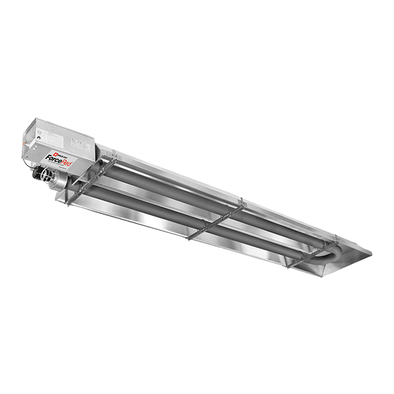
INFRARED RADIANT TUBE HEATER
Single and Two Stage Pull Through System (Negative Pressure)
NXU SERIES: (85, 110, 145, 175, 200) – (N5/L5) or (N7/L7)
NXS SERIES: (50, 85, 110, 145, 175, 200) – (N5/L5) or (N7/L7)
REFER TO PART A (NXU) AND B (NXS) ASSEMBLY INSTRUCTIONS
!INSTALLER: This manual is the property of the owner. Please present this manual to the
owner when you leave the job site.
▲WARNING: Improper installation, adjustment, alteration, service, or maintenance can
cause property damage, injury or death. Read the installation, operation and maintenance
instructions thoroughly before installing or servicing this equipment.
IF YOU SMELL GAS:
DO NOT try to light any appliance.
DO NOT touch any electrical switch; DO NOT use any
telephone in your building.
IMMEDIATELY call your gas supplier from a neighbor's
telephone. Follow the gas supplier's instructions. If you
cannot reach your gas supplier, call the fire department.
!IMPORTANT: SAVE THIS MANUAL FOR FUTURE REFERENCE.
Post Office Box 36485 (28236) • 305 Doggett Street (28203) • Charlotte, North Carolina
Phone (704) 372-6391 • Fax (704) 332-5843 • www.spaceray.com • email: info@spaceray.com
Models:
FOR YOUR SAFETY
DO NOT store or use gasoline or other
flammable vapors and liquids in the vicinity of
this or any other appliance.
SPACE-RAY
Form #43343342
Jan 2015
Advertisement
Table of Contents
Troubleshooting

Subscribe to Our Youtube Channel
Related Manuals for Space-Ray NXU 85


Summary of Contents for Space-Ray NXU 85
- Page 1 !IMPORTANT: SAVE THIS MANUAL FOR FUTURE REFERENCE. SPACE-RAY Post Office Box 36485 (28236) • 305 Doggett Street (28203) • Charlotte, North Carolina Phone (704) 372-6391 • Fax (704) 332-5843 • www.spaceray.com • email: info@spaceray.com...
-
Page 2: Table Of Contents
TABLE OF CONTENTS SECTION DESCRIPTION PAGE 1.0) Safety ..............................2 2.0) Installer Responsibility ........................2 3.0) General Information and Model Identification ................2 4.0) Minimum Clearances to Combustibles ................... 4 5.0) Typical Suspension Methods ......................5 6.0) Gas Connections and Regulations ....................6 7.0) Instructions for Pressure Test Gauge Connection ................. -
Page 3: Safety
1.0) SAFETY This heater is a self-contained infrared radiant tube heater. Safety information required during installation and operation of this heater is provided in this manual and the labels on the product. The installation, service and maintenance of this heater must be performed by a contractor qualified in the installation and service of gas fired heating equipment. - Page 4 a) At least 10 feet above the upper surfaces of wings or engine enclosures of the highest aircraft that may be housed in the hangar and at least 8 feet above the floor in shops, offices, and other sections of hangars communicating with aircraft storage or service areas.
-
Page 5: Minimum Clearances To Combustibles
“specify the maximum permissible stacking height to maintain the required clearances from the heater to combustibles.” Space-Ray recommends posting these signs adjacent to the heater thermostat or other suitable location that will provide enhanced visibility. -
Page 6: Typical Suspension Methods
6. Heaters must not be supported by gas or electric supply lines and must be suspended from a permanent structure with adequate load capacity. Space-Ray recommends that the body sections be suspended using chains with turnbuckles. This will allow slight adjustments after assembly and heater expansion/ contraction during operation. -
Page 7: Gas Connections And Regulations
6.0) GAS CONNECTIONS AND REGULATIONS IMPORTANT BEFORE CONNECTING THE GAS TO THE HEATER 1. Connect to the supply tank or manifold in accordance with the latest edition of National Fuel Gas Code (ANSI Z223.1), and local building codes. Authorities having jurisdiction should be consulted before the installation is made. -
Page 8: Instructions For Pressure Test Gauge Connection
US ONLY: Connector MUST be installed in “” configuration. Use only the 36” long connector that was furnished with this heater. US ONLY: A gas connector certified for use on a tubular type infrared heater per the standard for Connectors for Gas Appliances, ANSI Z21.24/CSA 6.10 is supplied for installation in US only. - Page 9 DO NOT EXCEED THE PRESSURES SHOWN IN THE GAS PRESSURE TABLE. 2. After testing pressure and adjusting the regulator, turn off all electrical power to the system, remove manometer hoses, turn outlet test screw (3/32” Hex) clockwise to seal pressure port. Tighten to 7 in lb minimum.
-
Page 10: Electrical Connections
GAS PRESSURE TABLE SUPPLY PRESSURE MANIFOLD PRESSURE GAS TYPE High Low (2-stage only) Minimum* Maximum Natural Gas 3.5” W.C. 1.4” W.C. 5” W.C. 14” W.C. Propane Gas 10.0” W.C. 4.0” W.C. 11” W.C. 14” W.C. *Minimum permissible gas supply pressure for purpose of input adjustment. 7”... - Page 11 NXS SERIES SINGLE STAGE CONTROLS ONLY: The installer will provide type SJO wire cable having minimum size of 18 AWG and connect the ends to the draft inducer junction box and the control box. Secure with 3/8” connectors as previously described in the attachment of the control box and draft inducer. Connect wire leads as shown in the Connection Wiring Diagram.
- Page 12 B. LINE VOLTAGE (120V) THERMOSTAT CONNECTIONS – MULTIPLE HEATERS PER THERMOSTAT C. LOW VOLTAGE (24V) THERMOSTAT CONNECTIONS – SINGLE HEATER PER THERMOSTAT Order 24V Relay Kit (Part No. 43274010) for Low Voltage (24V) thermostat connection. D. LOW VOLTAGE (24V) THERMOSTAT CONNECTIONS – MULTIPLE HEATERS PER THERMOSTAT Form #43343342 Jan 2015 -11-...
-
Page 13: Two Stage (N7/L7) - Internal And Thermostat Connections
8.2) TWO STAGE (N7/L7) - INTERNAL AND THERMOSTAT CONNECTIONS NXS SERIES TWO STAGE CONTROLS ONLY: The installer will provide type 3 core SJO cable having minimum size of 18 AWG to connect between the draft inducer junction box and the control box. See wiring diagram below. Secure with 3/8”... - Page 14 TWO STAGE CONTROLS - SCHEMATIC WIRING DIAGRAM TWO STAGE CONTROLS - THERMOSTAT WIRING DIAGRAMS A. LOW VOLTAGE (24V) THERMOSTAT CONNECTIONS – SINGLE HEATER PER THERMOSTAT B. LOW VOLTAGE (24V) THERMOSTAT CONNECTIONS – MULTIPLE HEATERS PER THERMOSTAT Form #43343342 Jan 2015 -13-...
- Page 15 C. MANUAL SWITCH CONNECTIONS – SINGLE HEATER OPERATION PER DUAL MANUAL SWITCH D. MANUAL SWITCH CONNECTIONS – MULTIPLE HEATERS OPERATION PER DUAL MANUAL SWITCH Form #43343342 -14- Jan 2015...
-
Page 16: Venting
9.0) VENTING A. BASIC FLUE VENTING — Venting must comply with the latest edition of the National Fuel Gas Code (ANSI Z223.1-latest edition) or the authority having jurisdiction. Other venting references are in the equipment volume of the ASHRAE Handbook. B. -
Page 17: Single Heater Venting (Vertical Through The Roof)
Maximum Fresh Air Maximum combined Fresh Maximum vent length intake length ft (4” Air and Vent length ft (4” Model ft (4” diameter) diameter) diameter NXU/S50 NXU/S85 NXU/S110 NXU/S145 NXU/S175, NXU/S200 9.1) SINGLE HEATER VENTING (VERTICAL THROUGH THE ROOF) 1. When venting the heater to outside of building through a roof, use Category approved material as defined in section B and as allowed by state or local codes. -
Page 18: Single Heater Venting (Horizontal Through The Sidewall)
9.2) SINGLE HEATER VENTING (HORIZONTAL THROUGH THE SIDEWALL) Horizontal venting less than 15ft total length When a ForceRed heater is installed with less than 15ft of horizontal vent then the system will be a positive pressure non-condensing system, this is a Category III vent system and flue materials which comply with UL 1738 shall be used. -
Page 19: Single Heater Venting (Concentric Vent)
9.3) SINGLE HEATER VENTING (CONCENTRIC VENT) Requirements for venting heaters with concentric vent are the same as described for SINGLE HEATER VENTING except as follows: 1. The concentric vent adaptor allows for the combustion air and vent piping with only one horizontal or vertical building penetration. - Page 20 The figure below shows the connection details for horizontal concentric venting for U-tubes. Below are typical arrangements for routing the concetric vent to the side wall. Form #43343342 Jan 2015 -19-...
-
Page 21: Multiple Heater Venting (Connections Into A Common Vent Or Manifold)
The figure below shows the connection details for vertical concentric venting thru roof. 9.4) MULTIPLE HEATER VENTING (CONNECTIONS INTO A COMMON VENT OR MANIFOLD) Requirements for venting of multiple heaters are the same as described for SINGLE HEATER VENTING except as follows: 1. - Page 22 If any heater connected to a common vent system for multiple heaters is found inoperative, the heater should be disconnected from the vent system and its entrance into the vent system capped. Multiple Heater Vertical Venting Arrangement Multiple Heater Horizontal Venting Arrangement Form #43343342 Jan 2015 -21-...
- Page 23 Multiple Heater Venting (Connections into a Manifold) VENT SIZING TABLE — Multiple Heater Venting Number of Heaters NXS-50 4” 4” 5” 5” 6” NXU,S-85 4” 4” 5” 5” 6” NXU,S-110 4” 5” 6” 6” 7” NXU,S-145 4” 6” 6” 7” 8”...
-
Page 24: Condensate Removal
E. INDIRECT VENTING (UNVENTED HEATERS) — This heater requires ventilation in the building to dilute the products of combustion and provide fresh air for efficient combustion. Where unvented heaters are used, gravity or mechanical means shall be provided to supply and exhaust at least 4 CFM per 1,000 Btu/hr. input of installed heaters. -
Page 25: Air For Combustion
11.0) AIR FOR COMBUSTION If indoor combustion air is to be supplied for a tightly enclosed area, one square inch of free area opening shall be provided below the heater for each 1,000 Btu/hr. per hour of heater input. When outside air is used, the opening below the heater shall be one square inch of free area for each 4,000 Btu/hr. - Page 26 In multiple heater applications, the combustion air intake may be ducted individually or common ducted in the same configuration as shown for venting in Section 9.0). For combustion air intake duct sizing, please refer to the Vent Sizing Table and use the diameter indicated, based on the number of heaters per duct. Form #43343342 Jan 2015 -25-...
-
Page 27: Lighting And Shutdown Instructions
12.0) LIGHTING AND SHUTDOWN INSTRUCTIONS 1. Turn on the gas and electrical supply. 2. Set the thermostat to call for heat. The blower motor will energize. 3. Ignition should occur after the 30-second air pre-purge. 4. If ignition fails, the unit will spark for approximately 21 seconds and go into safety lockout. Turn the thermostat (power) off for 60 seconds to take the system out of lockout. -
Page 28: Cleaning And Annual Maintenance
The chart below shows the sequence of operation for the normal operating cycle for a two stage heater (N7/L7). 14.0) CLEANING AND ANNUAL MAINTENANCE This heater must be cleaned and serviced annually by a qualified contractor before the start of each heating season and at any time excessive accumulation of dust and dirt is observed. - Page 29 Venting System: Disconnect vent pipe and inspect internally using a flashlight to make sure no foreign material has collected in the pipes. Check the external vent cap and make sure that there is no obstruction around the exhaust openings. Clean any foreign materials. Inspect any joints to make sure they are completely sealed. See also Section 9.0).
-
Page 30: Troubleshooting Guide - Single Stage (N5/L5)
15.0) TROUBLESHOOTING GUIDE – SINGLE STAGE (N5/L5) Form #43343342 Jan 2015 -29-... - Page 31 TROUBLESHOOTING GUIDE – SINGLE STAGE (CONTINUED) Form #43343342 -30- Jan 2015...
- Page 32 TROUBLESHOOTING GUIDE – SINGLE STAGE (CONTINUED) Form #43343342 Jan 2015 -31-...
-
Page 33: Troubleshooting Guide - Two Stage (N7/L7)
16.0) TROUBLESHOOTING GUIDE – TWO STAGE (N7/L7) Form #43343342 -32- Jan 2015... - Page 34 TROUBLESHOOTING GUIDE – TWO STAGE (CONTINUED) Form #43343342 Jan 2015 -33-...
- Page 35 TROUBLESHOOTING GUIDE – TWO STAGE (CONTINUED) Form #43343342 -34- Jan 2015...
- Page 36 TROUBLESHOOTING GUIDE – TWO STAGE (CONTINUED) Form #43343342 Jan 2015 -35-...
-
Page 37: Replacing Parts
17.0) REPLACING PARTS Only use genuine Space-Ray replacement parts. Parts are available from the factory for replacement by a licensed person. Refer to the Replacement Parts Guide in Section 18 for all replacement parts. 16.1 SPARK ELECTRODE The main burner can be inspected without removing the burner housing from the heat exchanger tube. -
Page 38: Air Switch Pressure Check
5. Observe air pressure from manometer. This should be higher than the set point indicated below for correct operation. Model Operating Pressure NXS 50 0.37 W.C. Hot NXS/NXU 85 0.37 W.C. Hot NXS/NXU 110 0.58 W.C. Hot NXS/NXU 145 0.52 W.C. Hot NXS/NXU 175 0.37 W.C. -
Page 39: Motor And Blower Wheel Check
c) Check the ground lead from the GND (BURNER) terminal on the module to the igniter bracket. Make sure connections are clean and tight. If the wire is damaged or deteriorated, replace it. d) Replace igniter/sensor with factory replacement part if insulator is cracked. TO CHECK SPARK IGNITION CIRCUIT. -
Page 40: Installation Data
17.0) INSTALLATION DATA Date of # of Heaters in Installation: System: Serial No. N = Natural Gas Model: NXS or NXU L = Propane Gas 18.0) REPLACEMENT PARTS GUIDE DRAFT INDUCER COMPONENTS Item No. Part No. Description 42917010 Draft Inducer Assembly – NXU/NXS 145 42917100 Draft Inducer Assembly –... - Page 41 Labels Item No. Part No. Description 42874000 Label, Wire Diagram – (1-stage controls) 42874040 Label, Wire Diagram – (2-stage controls) 42922020 Label, Sidewall Venting 43269060 Label, 24V Thermostat Connection – (2-stage controls) Form #43343342 -40- Jan 2015...
- Page 42 Label, 24V Supply 43270000 Label, Terminal ID (terminals 1 & 2) 24V Supply 42013060 Label, Space-Ray “ForceRed” Logo 42848000 Label, “Space-Ray” Nameplate – 1 Stage 42848110 Label, “Space-Ray” Nameplate – 2 Stage 43344170 Label, Clearance to Combustibles 43344050 Label, Gas Connector Warning...
- Page 43 Note: 1) Screws, Nuts and Washers are standard hardware items and can be purchased at any local hardware store. 2) Please order by PART NUMBER – not by Item Number. 3) Replacement Part Prices are available when ordering. 4) Please refer to complete Model Number when ordering. ALL ILLUSTRATIONS ARE INTENDED TO GIVE THE GENERAL IMPRESSION OF UNITS ONLY.
-
Page 44: Warnings Card
19.0) WARNINGS CARD Copies of this card may be ordered at no charge under part no. 43344990 for installation near the heater. Form #43343342 Jan 2015 -43-...
Need help?
Do you have a question about the NXU 85 and is the answer not in the manual?
Questions and answers