Table of Contents
Advertisement
Quick Links
Advertisement
Table of Contents

Related Manuals for AXIOMTEK GOT615-801


Summary of Contents for AXIOMTEK GOT615-801
- Page 1 GOT615-801 15.6” WXGA TFT LCD Fanless Extended Temperature PANEL PC User’s Manual...
- Page 2 Axiomtek does not make any commitment to update the information in this manual. Axiomtek reserves the right to change or revise this document and/or product at any time without notice. No part of this document may be reproduced, stored in a retrieval...
- Page 3 Safety Approvals CE Marking FCC Class B FCC Compliance This equipment has been tested in compliance with the limits for a Class B digital device, pursuant to Part 15 of the FCC Rules. These limits are meant to provide reasonable protection against harmful interference in a residential installation.
-
Page 4: Safety Precautions
Turn OFF the system power before cleaning. Clean the system using a cloth only. Do not spray any liquid cleaner directly onto the screen. The GOT615-801 may come with or w/o a touchscreen. Although the touchscreen is chemical resistant, it is recommended that you spray the liquid cleaner on a cloth first before wiping the screen. - Page 5 When handling boards and components, wear a wrist- grounding strap, available from most electronic component stores. Trademarks Acknowledgments Axiomtek is a trademark of Axiomtek Co., Ltd. IBM, PC/AT, PS/2, VGA are trademarks of International Business Machines Corporation. ® ™...
-
Page 6: Table Of Contents
Table of Contents Disclaimers ..................ii Safety Approvals ................iii Safety Precautions ................ iv CHAPTER 1 INTRODUCTION ..............1 General Description ............ 2 Specifications .............. 4 1.2.1 Main CPU Board ............4 1.2.2 I/O System ..............4 1.2.3 System Specification ........... 5 Dimensions .............. - Page 7 4.2.2 Driver Installation- Windows XP/WIN 7 ....66 Embedded O .S ............70 4.3.1 Windows XP Embedded ........... 70 Wake On LAN setting ..........71...
-
Page 8: Chapter 1 Introduction
GOT615-801 User’s Manual CHAPTER 1 INTRODUCTION This chapter contains general information and detailed specifications of the GOT615-801. Chapter 1 includes the following sections: General Description Specification Dimensions I/O Outlets Package List Introduction... -
Page 9: General Description
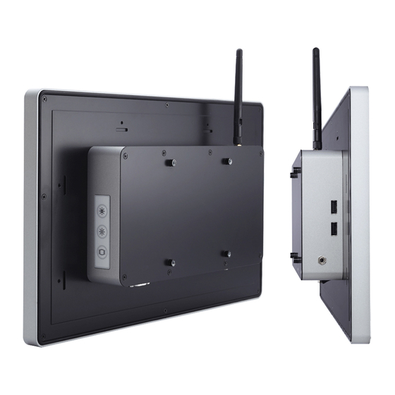
GOT615-801 User’s Manual General Description The GOT615-801 adopts a 15.6-inch W XGA color TFT LCD and low power consumption Intel® AtomTM processor D525 1.8 GHz to provide excellent computing performance and thermal resistance.With the growing demand of wireless application, it provides one Mini card slot. - Page 10 GOT615-801 User’s Manual WLAN Antenna Supported The GOT615-801 provides a PCI Express Mini card slot and WLAN antenna for wireless network connections. By simply plugging in the wireless LAN card, customers can use the unit in a wireless environment. More Features GOT615-801 utilizes one 204-pin DDR3 667/800MHz SODIMM system memory max.
-
Page 11: Specifications
GOT615-801 User’s Manual Specifications 1.2.1 Main CPU Board ™ D525 Processor with ( Intel® A Cache, System Chipset ○ Intel System Controller Hub ICH8M BIOS American Megatrends Inc. BIOS 4Mbit with RPL/PXE System Memory ... -
Page 12: System Specification
GOT615-801 User’s Manual 1.2.3 System Specification 15.6” W XGA(1366x768) LCD with LED backlight 5-wire resistive Touch Screen(Higgestec) Fanless Heat Dispensing Design IP65, NEMA 4 rugged protection, aluminum front bezel Disk drive housing: One 2.5” SATA drive ... -
Page 13: Dimensions
GOT615-801 User’s Manual Dimensions The following diagrams show the dimensions and outlines of GOT615-801. Introduction... - Page 14 GOT615-801 User’s Manual Introduction...
-
Page 15: I/O Outlets
GOT615-801 User’s Manual I/O Outlets Please refer to the following illustration for I/O locations of the GOT615-801. Introduction... - Page 16 GOT615-801 User’s Manual Introduction...
-
Page 17: Packing List
GOT615-801 User’s Manual Packing List When you receive the GOT615-801, the bundled package should contain the following items: GOT615-801 unit x 1 Driver CD x1 Adapter x 1 Screws M2x3L x 1 Screws M6B x 2 ... -
Page 18: Chapter 2 Hardware Installation
GOT615-801 series User’s Manual CHAPTER 2 HARDWARE INSTALLATION The GOT615-801 provides rich I/O ports and flexible expansions for you to meet different demand, for example, CF card. The chapter will show you how to install the hardware. It includes: ™... -
Page 19: Open
GOT615-801 User’s Manual Open back cover This section tells users how to open back cover. Please follow the steps below. Step 1 Unscrew 8 screws on the back cover. Please refer the photo below. Hardware Installation... - Page 20 GOT615-801 series User’s Manual Step 2 Remove the back cover. Hardware Installation...
-
Page 21: Cf Card Installation
GOT615-801 User’s Manual CF card Installation The GOT615-801 provides one CF slot for users to install ™ CompactFlash card. Please refer to the following instructions for installation: Step 1 Refer to section 2.1 to open the back cover and find out DIMM Socket on mainboard (CAPA801) from system. - Page 22 GOT615-801 series User’s Manual Step 2 Insert the card into the socket, Installation completes. Hardware Installation...
-
Page 23: Dram Installation
GOT615-801 User’s Manual DRAM Installation The GOT615-801 provides one 204-pin DDR3 667/800MHz SODIMM socket that support system memory up to 4GB. Please follow steps below to install the memory modules: Step 1 Refer to section 2.1 to open the back cover and find out DIMM Socket on mainboard (CAPA801) from system. - Page 24 GOT615-801 series User’s Manual Step 2 Pulg DDR3 667/800MHz SODIMM 204-pin memory into slot with angle of 45° Step 3 Press the memory into slot. Hardware Installation...
-
Page 25: Hdd Installation
GOT615-801 User’s Manual HDD Installation The GOT615-801 provides a convenient Hard Disk Drive (HDD) bracket for users to install 2.5” SATA HDD. Please follow the steps: Step 1 Refer to section 2.1 to open the back cover. Hardware Installation... - Page 26 GOT615-801 series User’s Manual Step 2 Take the HDD bracket from the accessories and fix the HDD bracket. Hardware Installation...
- Page 27 GOT615-801 User’s Manual Step 3 Fix the HDD on bracket by 4 screws at the side corner. Hardware Installation...
- Page 28 GOT615-801 series User’s Manual Step 4 Fix the HDD bracket into the system, and plug the data and power cables to HDD. Installation completed. Hardware Installation...
- Page 29 GOT615-801 User’s Manual Hardware Installation...
-
Page 30: Wireless Lan Card Installation (Option)
GOT615-801 series User’s Manual 2.5 Wireless LAN Card Installation (option) The GOT615-801 provides one Mini card slot for user to install one wireless LAN card. W hen installing the wireless LAN card, refer to the following instructions and illustratio n: Step 1 Refer to section 2.1 to open the back cover and find... - Page 31 GOT615-801 User’s Manual Hardware Installation...
- Page 32 GOT615-801 series User’s Manual Setp 3 Fix the card on the M/B by a screw (M2x3L) at the side corner. Hardware Installation...
- Page 33 GOT615-801 User’s Manual Step 4 Connecting the Antenna cable with wireless LAN card Hardware Installation...
- Page 34 GOT615-801 series User’s Manual Step 5 Install the antenna on the antenna connector. Hardware Installation...
-
Page 35: Serial Ports Interface
GOT615-801 User’s Manual Serial Ports Interface The GOT615-801 has threer serial ports. COM1 is RS-232/422/485, while COM2 and COM3 are RS-232. The following table shows you the pin assignments of this connector: Signal Signal Data Carrier Detect (DCD) Data Set Ready (DSR) - Page 36 GOT615-801 series User’s Manual The COM2 ports have +5V level power capability on DCD and +12V level power capability for RI, depending on the JP8 setting. Description Mode Jumper Setting Power; Pin 1 +5V level Data; Pin 1 DCD (Default) COM2 Powe;r...
- Page 37 GOT615-801 User’s Manual The COM3 ports have +5V level power capability on DCD and +12V level power capability for RI, depending on the JP7 setting. Description Mode Jumper Setting Power; Pin 1 +5V level Data; Pin 1 DCD (Default) COM3 Powe;r...
- Page 38 GOT615-801 series User’s Manual COM1 can be set for RS-232/422/485 by jumper. The jump setting is listed as below: COM1 RS-232/422/485 Mode Select Jumpers (JP4, JP5, JP6) Description Mode Jumper Setting RS-232 (Default) COM 1 RS-422 RS-485 When COM1 is set to RS-232,RS-422 or RS-485, the pin assignments...
- Page 39 GOT615-801 User’s Manual The COM1 ports have +5V level power capability on DCD and +12V level power capability for RI, depending on the JP10 setting. W hen COM1 is set +5V level or +12V level, please make sure the Mode is RS-232...
-
Page 40: Ethernet Connector (Lan1, Lan2)
GOT615-801 series User’s Manual Ethernet Connector (LAN1, LAN2) The GOT615-801 is equipped with a high performance Plug and Play Ethernet interface, full compliant with IEEE 802.3 standard, and can be connected with a RJ-45 LAN connector. The RJ-45 connector is for Ethernet. To connect the board to a 1000/100/10 Base-T hub, just plug one end of the cable into connector and connect the other end (phone jack) to a 1000/100/10-Base-T hub. - Page 41 GOT615-801 User’s Manual Hardware Installation...
-
Page 42: Mountings: Vesa / Wall
GOT615-801 series User’s Manual Mountings: VESA / WALL There application options GOT 615-801, Panel/VESA mountings. 2.8.1 VESA-ARM The GOT615-801 provides 100x100 VESA mount. Screw four screws to fix the kit (optional) in the back chassis. Hardware Installation... -
Page 43: Wall Mounting
GOT615-801 User’s Manual 2.8.2 WALL mounting The GOT615-801 is designed for Wall mounting application. Please refer to the following: Find out the screws as marked on the back side of chassis. Hardware Installation... - Page 44 GOT615-801 series User’s Manual Hardware Installation...
-
Page 45: Power
GOT615-801 User’s Manual Power GOT615-801 equips with a screw type power connector. It adopts 12VDC. Please follow the signs on power connector to connect DC power source. Note: The safty ground must be connected to ensure the uiit working appropriately. -
Page 46: Chapter 3 Ami Bios Setup Utility
GOT615-801 series User’s Manual CHAPTER 3 AMI BIOS SETUP UTILITY This chapter provides users with detailed description how to set up basic system configuration through the AMI BIOS setup utility. 3.1 Starting To enter the setup screens, follow the steps below: Turn on the computer and press the <Del>... - Page 47 GOT615-801 User’s Manual AMI BIOS Setup Utility...
-
Page 48: Main Menu
GOT615-801 series User’s Manual Main Menu When you first enter the Setup Utility, you will enter the Main setup screen. You can always return to the Main setup screen by selecting the Main tab. System Time/Date can be set up as described below. The Main BIOS Setup screen is shown below. -
Page 49: Advanced Menu
GOT615-801 User’s Manual Advanced Menu The Advanced menu allows users to set configuration of the CPU and other system devices. You can select any of the items in the left frame of the screen to go to the sub menus: ... - Page 50 GOT615-801 series User’s Manual Configure advanced CPU settings This screen shows the CPU Configuration, and you can change the value of the selected option. Execute-Disable Bit Capability Use this item to enable or disable the No-Execution Page Protection Technology.
- Page 51 GOT615-801 User’s Manual IDE Configuration Use this screen to select options for the IDE Configuration and change the value of the selected option. Available options of the selected item appear on the right side of the screen. For items marked with “”, please press <Enter> for more options.
- Page 52 GOT615-801 series User’s Manual Super IO Configuration Use this item for the Super IO Configuration, and change the value of the selected option. Serial Port1 Address This item specifies the base I/O port address and Interrupt Request address of serial port 1. The Optimal setting is 3F8/IRQ4.
- Page 53 GOT615-801 User’s Manual Hardware Health Configuration This item shows the Hardware Health Configuration, which displays the temperature of System, CPUFAN Speed and Vcore, +12V, +5V, +3.3V. AMI BIOS Setup Utility...
- Page 54 GOT615-801 series User’s Manual ACPI Settings Use this item to select options for the ACPI Settings, and change the value of the selected option. General ACPI Configuration Scroll this item and press <Enter> to view th e General...
- Page 55 GOT615-801 User’s Manual General ACPI Configuration/Suspend mode Use this item to select which in the Advanced Configuration and Power Interface(ACPI) state to be used for system suspend. Here are the options for your selection, S1(POS), S3(STR) and Auto. AMI BIOS Setup Utility...
- Page 56 GOT615-801 series User’s Manual AHCI Configuration Use this item to select options for the AHCI Configuration and change the value of the selected option . AMI BIOS Setup Utility...
- Page 57 GOT615-801 User’s Manual APM Configuration Use this item to select options for the APM Configuration, and change the value of the selected option. Available options of the selected item appear on the right side of the screen. Power Management/APM Set this item to allow Power Management/APM support.
- Page 58 GOT615-801 series User’s Manual Video Power Down Mode This option specifies the Power State. When the BIOS places it in a power saving state, the video subsystem enters when the BIOS places it in a power saving state after the specified period of display inactivity has expired.
- Page 59 GOT615-801 User’s Manual USB Configuration this item select options Configuration, and change the value of the selected option. USB Function Use this item to enable or disable USB function. USB 2.0 Controller Use this item to enable or disable the USB 2.0 controller.
-
Page 60: Boot Menu
GOT615-801 series User’s Manual Boot Menu The Boot menu allows users to change boot options of the system. You can select any of the items in the left frame of the screen to go to the sub menus: Boot Settings Configuration ... - Page 61 GOT615-801 User’s Manual Boot Settings Configuration Quick Boot Enabling this item lets the BIOS skip some power on self tests (POST). The default setting is Enabled. Bootup Num-Lock Use this item to select the power-on state for the NumLock.
- Page 62 GOT615-801 series User’s Manual LAN Boot Option Use these items to enable or disable the Boot ROM function of the onboard LAN chip when the system boots up. Available options of the selected item appear on the right side of the screen.
-
Page 63: Security Menu
GOT615-801 User’s Manual Security Menu The Security menu allows users to change the security settings for the system. Supervisor Password This item indicates whether a supervisor password has been set. If the password has been installed, 『 Installed 』... -
Page 64: Chipset Menu
GOT615-801 series User’s Manual Chipset Menu The Chipset menu allows users to change the advanced chipset settings. You can select any of the items in the left frame of the screen to go to the sub menus: North Bridge Configuration ... - Page 65 GOT615-801 User’s Manual North Bridge Configuration Initate Graphic Adapter When using multiple graphics cards, this item can select which graphics controller to be the primary display device during boot. Internal Graphics Mode Select This item allows you to select the amount of system memory used by the internal graphics device.
- Page 66 GOT615-801 series User’s Manual Video Function Configuration DVMT Mode Select Allow you to select DVMT (Dianomic Video Memory Technology) mode and Fixed Mode. DVMT/FIXED Memory Allow you to allocate a fixed amount of system memory as graphics memory. Here are the options for your selection, 128MB, 256MB and Maximum DVMT ...
- Page 67 GOT615-801 User’s Manual Flat Panel Type : 1366x768(only) 18 bit AMI BIOS Setup Utility...
- Page 68 GOT615-801 series User’s Manual South Bridge Configuration HDA Controller This item allows you to enable or disabled the HD audio support. AMI BIOS Setup Utility...
-
Page 69: Exit Menu
GOT615-801 User’s Manual Exit Menu The Exit menu allows users to load the system configuration with optimal or failsafe default values. Save Changes and Exit W hen you have completed the system configuration changes, select this option to leave Setup and reboot... - Page 70 GOT615-801 series User’s Manual Discard Changes Use this item to abandon all changes. Load Optimal Defaults It automatically sets all Setup options to a complete set of default settings when you select this option. The Optimal settings are designed for maximum system performance, but may not work best for all computer applications.
- Page 71 GOT615-801 User’s Manual MEMO: AMI BIOS Setup Utility...
-
Page 72: Chapter 4 Drivers Installation
GOT615-801 series User’s Manual CHAPTER 4 DRIVERS INSTALLATION System GOT615-801 supports Windows XP and WIN 7. To facilitate the installation of system driver, please carefully read the instructions in this chapter before start installing. Insert Driver CD and select the “\Drivers”. -
Page 73: Touch Screen
Active: 24.6mA / Idle Mode: 13.4mA 4.2.2 Driver Installation- Windows XP/WIN 7 The GOT615-801 provides a touch screen driver that users can install it under the operating system Windows XP/Win 7. To facilitate installation of the touch screen driver, you should read the instructions in this chapter carefully before you attempt installation. - Page 74 GOT615-801 series User’s Manual Follow the installing procedure and press OK. Click Start menu and select “PenMount Utilities”; and then, a “PenMount Control Panel” pops out. Installation of Drivers...
- Page 75 GOT615-801 User’s Manual Select the “Standard Calibrate” tab. Installation of Drivers...
- Page 76 GOT615-801 series User’s Manual Calibration: To adjust the display with touch panel, click “Calibration” and follow the calibrate point to do calibration; there are five points on screen for calibration. Press OK. Installation of Drivers...
-
Page 77: Embedded O .S
GOT615-801 User’s Manual Embedded O .S The GOT615-801 provides the W indows XP Embedded. The O.S. is supported devices which are listed below. 4.3.1 Windows XP Embedded Here are supported onboard devices: Onboard Multi I/O SATA HDD ... -
Page 78: Wake On Lan Setting
GOT615-801 series User’s Manual Wake On LAN setting The GOT615-801 supports the wake on LAN function. Please make the following setting when using this function under W IN XP and XPE. Installation of Drivers... - Page 79 GOT615-801 User’s Manual Installation of Drivers...
Need help?
Do you have a question about the GOT615-801 and is the answer not in the manual?
Questions and answers