Advertisement
Quick Links
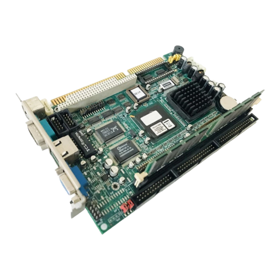
PCA-6753 GX1 SBC with CPU, VGA/LCD and
Ethernet
Startup Manual
Packing List
Before you begin installing your board, please make
sure that the following materials have been shipped:
• 1 PCA-6753 Series all-in-one single board computer
• 1 startup manual
• 1 utility disk/CD driver, and manual (in PDF format)
• 1 hard disk drive (IDE) interface cable (40-pin)
(part no. 1701400601)
• 1 keyboard / PS2 mouse cable (part no.
1700060201)
• COM port/parallel port cable (part no. 1701260303)
• 1 USB cable (part no. 1700100170)(optional)
• 1 IrdA adapter (part no. 968900042)(optional)
• 1 floppy disk drive interface cable 700 mm (28")
(part no. 1701340700)
• 1 ATX/AT power cable (part no. 1700000450) and
converter (part no. 1700040052 )
• 1 COM3, 4 Cable (part no. 1701200220)
(PCA-6753FC-G0V1 only)
• 1 Warranty Certificate
If any of these items are missing or damaged, contact
your distributor or sales representative immediately.
Note 1:
For detailed contents of the PCA-6753
Series please refer to the enclosed CD-
ROM or disk (in PDF format).
Note 2:
Acrobat Reader is required to view any PDF
file. Acrobat Reader can be downloaded at:
www.adobe.com/Prodindex/acrobat/
readstep.html
(Acrobat is a trademark of Adobe.)
For more information on this and other Advantech
products, please visit our website at:
http://www.advantech.com
http://www.advantech.com/epc
For technical support and service, please visit our support
website at:
http://www.advantech.com/support
This manual is for the PCA-6753 series Rev.A3
Part No. 2006675312
Printed in Taiwan
Specifications
Standard SBC Functions
• CPU: Embedded Low Power 2.0 V 300/233 MHz NS GX1
processor
• BIOS: AWARD 256 KB Flash BIOS
• System memory: SDRAM DIMM x 1 Max. 128 MB
• Enhanced IDE interface: Supports up to two IDE
devices. BIOS auto-detect, PIO Mode 3 or Mode 4
transfer, Ultra DMA33 mode (ATA-4) up to 33 MB/sec (w/
Driver installation)
• FDD interface: Supports up to two FDD devices
• Serial ports: 2 serial ports: COM1 (RS232), COM2
(RS232/422/485), 4 serial ports for PCA-6753FC-G0B1
only: COM1, 3 and 4 (RS-232), COM2 (RS232/422/485)**
• Parallel port: One parallel port, supports EPP/EPC
mode
• Infrared port: One 115 K fast infrared (SIR) port, IrDA
1.1 compliant
• Keyboard/mouse connector: Mini-Din connector
supports standard PC/AT keyboard and PS/2 mouse
• USB interface: 2 USB ports, USB 1.0 compliant
• Power management: APM 1.2
• Watchdog timer: 1 ~ 62 sec. System reset or IRQ11
Local-bus Flat Panel/VGA Interface
• Chipset: NS CS5530A
• Display memory: 1 ~ 4 MB share memory, set in BIOS
• Display type: Supports CRT and TFT LCDs. Able to
display both CRT and flat panel simultaneously
• Flat-panel display mode: Panel resolution supports up
to 1024 x 768 @ 16 bpp. Supports 18-bit TFT LCD panel
• CRT display mode: Non-interlaced CRT monitor
resolutions up to 1280 x 1024 @ 256 colors or 1024 x
768 @ 16 bpp
Ethernet Interface (PCA-6753F)
• Chipset: RTL 8139
• Ethernet interface: PCI 10/100 Mbps Ethernet. IEEE
802.3 U protocol compatible
• Connection: On-board RJ-45 connector
• I/O address switchless setting
• Built-in boot ROM
3rd Edition
• Supports Wake-on-Lan
Mar. 2001
** Please Note: COM mouse cannot share IRQ with other three COMs
PCA-6753 Series Startup Manual
1
Advertisement

Related Manuals for Advantech PCA-6753


Summary of Contents for Advantech PCA-6753
- Page 1 • CPU: Embedded Low Power 2.0 V 300/233 MHz NS GX1 processor • 1 PCA-6753 Series all-in-one single board computer • BIOS: AWARD 256 KB Flash BIOS • 1 startup manual • System memory: SDRAM DIMM x 1 Max. 128 MB •...
-
Page 2: Jumpers And Connectors
The tables below lists the function of each of the board's jumpers and connectors: Table 2-1: Jumpers Label Function PCA-6753 Locating jumpers (component side) J P 1 LCD Voltage select & Wake-up on LAN ® J P 8 2000 Address select... - Page 3 External speaker connection JP4: 5-7 Result Closed Internal speaker enabled Open Internal speaker disabled D4000- DC000- D8000- D5FFF DDFFF D9FFF CC000- C8000- D000- D1FFF* CDFFF D9FFF CN21 Multiple connector location JP10: RS-232/RS-422/RS-485 select Function COM2/232 COM2/422 COM2/485 PCA-6753 Series Startup Manual...
-
Page 4: Mechanical Drawings
Mechanical Drawings JP9: Multiple Connection (1-3-5) Watchdog timer Function IRQ 11 Reset* IRQ11 Reset* (2-4-6) CMOS clear Function Normal* Clear CMOS Normal* Clear CMOS Board Dimensions (solder side) Locating connectors (solder side) Board Dimensions (component side) PCA-6753 Series Startup Manual...