
Related Manuals for Gossen MetraWatt METRATESTER 5+


Summary of Contents for Gossen MetraWatt METRATESTER 5+
- Page 1 Operating Instructions ⏐ METRA Workshop Test Panel for Testing Devices 3-349-414-03 per DIN VDE 0701-0702 and DIN VDE 0104 6/2.11...
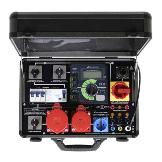
- Page 2 1 NETZ-VDE switch (mains-VDE) 12 RCD (residual current circuit beaker) 4*25 A, 0.03 A 2 Measuring selector switch: L1-L2-L3 13 Three circuit breakers, B16 A 3 Connector socket/terminal for DUT phase conductor (parallel to test sockets) 14 Polarity reversing switch 4 Connector socket/terminal for DUT pro- 15 CEE socket, 3P+N+PE, 32 A, 230/400 V tective conductor (parallel to test sockets)
-
Page 3: Table Of Contents
Table of Contents Page Applications ........................4 Safety Precautions ......................4 Standard Equipment and Accessories ................6 Connecting the Test Case to the Mains and Testing the Mains Connection ......6 4.1 Connecting the Test Case ......................... 6 4.2 Testing Protective Conductor Potential ....................6 4.3 Measuring Line Voltage ........................ -
Page 4: Applications
11.5 Fuse Replacement .......................... 26 11.6 Return and Environmentally Sound Disposal ..................26 12 Repair and Replacement Parts Service Calibration Center * and Rental Instrument Service .............27 13 Product Support ......................28 Applications The portable test case, manufactured in accordance with “guidelines for equipment required for electrical installation operations”, is intended for use by qualified electricians for measuring and testing electrical devices after repair or modifications, as well as for periodic testing, in accordance with DIN VDE 0701-0702. - Page 5 Observe the following safety precautions: • Measurements within electrical systems are prohibited! • The test case may only be connected to 230/400 V mains system with 50 Hz and a 16 A fuse via the 5-pole (23) or 3-pole (22) mains cable. •...
-
Page 6: Standard Equipment And Accessories
Meaning of Symbols on the Instrument Warning concerning a source of danger (attention: observe documentation!) EC label of conformity This device may not be disposed of with the trash. Further information regarding the WEEE mark can be accessed on the Internet at www.gossenmetrawatt.com by entering the search term WEEE. -
Page 7: Measuring Line Voltage
When connected via the 5-pole CEE mains plug (23), indicator lamps L1, L2 and L3 (19) must light up. When connected via the earthing contact mains adapter (22), only indicator lamp L1 should light up. Mains polarity is tested for this type of connection, i.e. if lamp L1 does not light up, the polarity of the earthing contact plug must be reversed in the mains outlet. -
Page 8: Connecting The Dut To The Test Case
Connecting the DUT to the Test Case It is absolutely mandatory to execute the tests in the order in which they are specified here! 1 Visual inspection 2 Measurement of protective conductor resistance for protection class I devices 3 Measurement of insulation characteristics if technically feasible, i.e. if the DUT does not include any electrically actuated, all-pole switches: –... -
Page 9: Protection Class Ii And Iii Devices
Protection Class II and III Devices Either Connect the DUT, for example to the earthing contact outlet, or to the connec- tor sockets in the case of loose wire ends. To Accessible Metal Parts Mains Connection Sockets Switch the DUT on! Devices with Single or Multi-Phase Connection without Plug Either Switch the DUT on! -
Page 10: Stationary Devices For Protective Conductor Testing Via The Supply Mains
Stationary Devices for Protective Conductor Testing via the Supply Mains Either Mains Connection Sockets Switch the DUT on! Data Processing Equipment Either Switch the DUT on! Mains Connection Sockets GMC-I Messtechnik GmbH... -
Page 11: Extension Cables With The Vl2 E Accessory
Extension Cables with the VL2 E Accessory Either Mains Connection Sockets VL2 E Test Adapter Setting the Switches at the Test Case The following settings must be made after visual inspection has been passed, and before the DUT is connected to the corresponding plug connectors at the test case, as well as before each new test: NETZ–VDE switch (1) Set to “VDE”... -
Page 12: Testing Devices In Accordance With Din Vde 0701-0702
Testing Devices in Accordance with DIN VDE 0701-0702 Always measure protective conductor resistance first for safety class I devices under test. Measurement of insulation resistance, equivalent leakage current and protective conductor current is not possible without a properly functioning protective conductor. This measurement is of special importance because a defective or reversed protective conductor may represent a hazard for the user! ... -
Page 13: Measuring Insulation Resistance
Attention The connector cable must be shaken back and forth, section by section over its entire length, during measurement (for permanently installed devices only insofar as the connector cable is accessible during repair, modification or testing). Unrealistic, continuously changing measured values indicate poor contact, a damaged protective conductor or a broken core in the probe cable (21) in the event that it has been excessively stressed! If brief or continuous interruption of the protective conductor occurs during the manual step of the continuity test, the limit value indicator at the... - Page 14 Limit Values per DIN VDE 0701-0702, Part 1: 2008 Device Type Limit Values Min. Display Value Protection class I devices 1MΩ 1.15 MΩ Protection class I devices with heating elements 0.3 MΩ 0.38 MΩ Protection class II devices 2.0 MΩ 2.25 MΩ...
-
Page 15: Measuring Protective Conductor Resistance
Measuring Protective Conductor Resistance 6.3.1 Equivalent Leakage Current In accordance with DIN VDE 0701-0702:2008, protective conductor resistance must be measured after the performance of the insulation resistance measurement. We recommend equivalent leakage current measurement. The limit value is: • 3.5 mA for protection class I devices whose exposed conductive parts are connected to the protective conductor. -
Page 16: Differential Current Measurement For Protection Class I Devices
6.3.2 Differential Current Measurement for Protection Class I Devices This test must be executed for all devices for which it is not possible to measure insulation resistance at all safety relevant parts (practically all DUTs with electrically actuated switches and relays), or where there is any doubt regarding measurement with insulation voltage, for example at electronic devices. -
Page 17: Measuring Contact Current
Measuring Contact Current 6.4.1 Contact Current Measurement – Differential Current This test must be executed for all protection class II devices, as well as protection class I devices with exposed conductive parts which are not connected to the protective conductor (practically all DUTs with electrically actuated switches and relays). -
Page 18: Measuring Load Current And Voltage At The Consumer
Ð Connect a measurement cable with test probe to the socket/terminal (5), and contact all exposed conductive parts at the DUT, or all conductive parts which are not connected to the protective conductor at protection class I devices. Ð Set the measuring function selector switch (6) at the METRATESTER 5+ test instrument to the “I 2 m”... -
Page 19: Testing Extension Cables With The Vl2 E Accessory
Testing Extension Cables with the VL2 E Accessory Testing in accordance with the wiring diagram in section 5.6 DIN VDE Tests for Extension Cables Always set the NETZ-VDE switch (1) to “VDE” for these tests. Protective Conductor Resistance Measurement Perform test as described in section 6.1. The probe cable (21) is connected to the SI socket in the VL2 E test adapter. -
Page 20: Continuity Test With Extra-Low Voltage
The display can settle in within a range of 0 Ohm (if all cores are short-circuited) up to, for example, infinity (in the event of overload) if one core is interrupted. Due to good insulation assured by undamaged cables, a test value of 10 MOhm with a tolerance of 20% has been established for this rational test procedure. -
Page 21: Technical Data
The following limit values are indicated: Indication of Exceeded Limit Value at the Test Instrument Fault Condition per Measurement Standard Continuously Lit Display of Limit Continuous Red Error Lamp Values Buzzing (beeper) > 0.3 Ω • > 0.3 Ω — Protective conduc- tor resistance >... -
Page 22: Metratester 5+ Test Instrument
10.2 METRATESTER 5+ Test Instrument Measuring Qty. Measuring Range Resolution U no-load 0 … 19.99 Ω < 20 V − Protective 10 mΩ — > 200 mA conductor resistance 0.05 … 19.99 MΩ 600 V − Insulation 10 KΩ Approx. <... - Page 23 Influencing Quantities and Influence Error Influencing Quantity / Designation Influence Error ± … % of the measured values Sphere of Influence per DIN VDE 0404 Change of position — Change to test equipment supply voltage Temperature fluctuation Specified influence error valid starting with temperature changes as of 10 K: °...
- Page 24 Electrical Safety Protection class Nominal line voltage 230 V Test Voltage Mains + PE (mains) + 2 mA socket for testing for absence of voltage at test socket, connector sockets for phase and protective conductors, as well as clip: 3 kV∼ mains to PE (mains) + 2 mA socket 1.5 kV∼...
-
Page 25: Maintenance - Recalibration
Maintenance – Recalibration 11.1 Housing Maintenance No special maintenance is required. Keep outside surfaces clean and dry. Use a slightly dampened cloth for cleaning. Avoid the use of solvents, cleansers and abrasives. Note! If the test case has not been used for a long period of time, the switches may demonstrate increased contact resistance depending upon storage conditions. -
Page 26: Periodic Self-Test Of The Connector Cable For Protective Conductor Continuity
11.3 Periodic Self-Test of the Connector Cable for Protective Conductor Continuity Connect the probe cable (21) to a grounding contact which has been previously tested for absence of voltage (e.g. at an electrical outlet), and which is connected to the protective conductor in the connector cable, and set the NETZ-VDE switch (1) to “NETZ”. - Page 27 Repair and Replacement Parts Service Calibration Center * and Rental Instrument Service If required please contact: GMC-I Service GmbH Service Center Thomas-Mann-Str. 20 90471 Nürnberg, Germany Phone +49 911 817718-0 +49 911 817718-253 E-mail service@gossenmetrawatt.com www.gmci-service.com This address is only valid in Germany. Please contact our representatives or subsidiaries for service in other countries.
-
Page 28: Product Support
Product Support If required please contact: GMC-I Messtechnik GmbH Product Support Hotline Phone +49 911 8602-112 +49 911 8602-709 E-mail support@gossenmetrawatt.com Edited in Germany • Subject to change without notice • PDF version available on the Internet Phone: +49 911 8602-111 GMC-I Messtechnik GmbH Fax: +49 911 8602-777...
Need help?
Do you have a question about the METRATESTER 5+ and is the answer not in the manual?
Questions and answers