Table of Contents
Advertisement
Quick Links
Advertisement
Table of Contents

Related Manuals for Gossen MetraWatt METRAHIT Cal


Summary of Contents for Gossen MetraWatt METRAHIT Cal
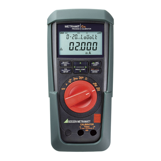
- Page 1 Operating Instructions METRAHIT⏐C 3-349-442-03 Calibrator 9/2.15...
- Page 2 Operating Overview – Connections, Keys, Rotary Switch, Symbols 1 Display (LCD) (see page 3 for significance of symbols 2 HOLD / CONT Pause/resume ramp/interval Increase parameter values Mode menu: Selection of individual menu entries against direction of flow 3 ON / OFF | LIGHT, key for switching device and display illumination on and off 4 OUT | ENTER OUT: Switch calibrator output on and off...
- Page 3 Symbols used in the Digital Display 1 Battery level indicator 2 NUM: Numeric entry of the output signal 3 INT: Interval sequence active 4 RAMP: Ramp function active 5 SINK: Current sink is active 6 SOURCE: Current source is active 7 ON: The calibrator output is active 8 IR:...
-
Page 4: Table Of Contents
Table of Contents Page Page Safety Features and Precautions ............5 Maintenance .................29 12.1 Displays – Error Messages ................29 Initial Start-Up .................7 12.2 Batteries ...................... 29 12.3 Fuses ......................30 Voltage Source [V] ................8 12.4 Housing Maintenance ................... 31 Frequency Generator (positive square-wave pulses) [Hz] ....9 12.5 Return and Environmentally Sound Disposal ........... -
Page 5: Safety Features And Precautions
Safety Features and Precautions • Make certain that the measurement cables are in flawless condition, e.g. no damage to insulation, no interruptions in You have selected an instrument which provides you with a high cables or plugs etc. level of safety. •... - Page 6 Meanings of Symbols on the Instrument Opening of Equipment / Repair The equipment may be opened only by authorized service per- Warning concerning a source of danger sonnel to ensure the safe and correct operation of the equipment (attention: observe documentation!) and to keep the warranty valid.
-
Page 7: Initial Start-Up
Initial Start-Up Switching the Instrument On with a PC After transmission of a data frame from the PC, the simulator is Battery operation switched on. See also section 10.1. Be certain to refer to section 12.2 regarding correct battery Note! installation. -
Page 8: Voltage Source [V]
Voltage Source [V] Selecting a Voltage Range for the Fixed Value Function ➭ Press the ZERO/SEL | ESC key in order to switch to the Voltages can be simulated within the following ranges: 0 … ±60 mV, 0 … ±300 mV, 0 … 3 V, 0 … 10 V and 0 … 15 V. select range ] menu. -
Page 9: Frequency Generator (Positive Square-Wave Pulses) [Hz]
Frequency Generator (positive square-wave pulses) [Hz] Note! Voltage and frequency can be set independent of each other for The following error messages are possible: frequency generators. “HiCurr” (high current – current at overload limit) where The output signal is a square wave. Resistance of the connected = 18 mA, “0ut 0l”... -
Page 10: Resistance Simulation [Ω]
Resistance Simulation [Ω] Abbreviated Instructions The resistance simulator is capable of simulating resistors using Select the calibration function. Ω 2-wire connection for the following range: 5 … 2000 Ω. ON/OFF 2-Wire Resistance Simulation LIGHT CALIBRATOR – Output Change the fixed value. Device to be Calibrated 0000.0 Ω... -
Page 11: Temperature Simulation [°C / °F]
Temperature Simulation [°C / °F] Query internal reference temperature – Info menu. The temperature simulator is capable of simulating resistance MEAS/CAL 2.9 V ... temperature detectors (RTD) or thermocouples (TC) with info 23.7 °C batt temp internal SETUP ENTER specification of the external reference junction temperature. -
Page 12: Temperature Simulation For Resistance Temperature Detectors - Rtd Setting For Temperature
6.1 Temperature Simulation for Resistance Temperature Detectors – Temperature Simulation for Thermocouples – TC Temperature Setting RTD setting for temperature Thermocouples (types B, E, J, K, L, N, R, S, T and U) are Resistance temperature detectors (types Pt100, Pt1000, Ni100 simulated with voltage. - Page 13 Function Description and Applications Attention! 10 different types of thermocouples can be selected, and can be No interference voltage may be applied to the calibrator simulated within the temperature ranges specified by IEC/DIN. jacks in this operating mode. Selection can be made between an internally measured reference The calibrator is protected against brief application of a junction temperature, or numeric entry of an external reference large interference voltage with a replaceable fuse in the...
-
Page 14: Current Source And Current Sink [Ma]
Current Source and Current Sink [mA] Abbreviated Instructions ➭ Connect the device to be calibrated with the measurement Select the calibration function. cables (see example in section 7.1). ➭ Select the mA current sink ( ) or mA current source ( ON/OFF calibration function with the rotary switch. -
Page 15: Current Sink - Simulation Of A 2-Wire Transmitter
7.1 Current Sink – Simulation of a 2-Wire Transmitter 7.2 Current Source A current sink (0 … 24 mA) or current loop load can be simulated Internal supply power is used to simulate a current source. with this function. The calibrator regulates the current, which flows via the calibrator jacks from an external power supply Note! independent of direct voltage applied to the jacks (4 …... -
Page 16: Interval Functions, Ramp Functions And Procedures
= manual) with Interval Functions, Ramp Functions and Procedures • Step jumps can be executed manually ( 1nt mode the and keys, or automatically ( = Auto ) with 1nt mode Two types of setpoint sequences can be generated in order to selectable time per step. - Page 17 Setting the Interval Parameters Example of a Manually Controlled Interval Sequence ZERO/SEL MEAS/CAL Source 300 mV … 15 V 1nt seleCt range [mA] SETUP manual stop 02.000 V Initial value: 1nt start ENTER 10.000 V Final value: 1nt end...
- Page 18 Automatic Interval Sequence Example of an Automatic Interval Sequence Automatic execution of a programmed sequence range is above U [V] all advisable if feeding to a signal circuit and scanning of the run up run dn hold run up run dn stop LCD: peripheral device under test are physically separated.
-
Page 19: Read-Out A Periodic Ramp - Ramp Function
8.2 Read-Out a Periodic Ramp – RAMP Function Examples of Ramp Sequences Ramp-type signals can be used to test the dynamic performance 3, 0, 0 (t1, t2, t3) 0, 0, 3 (t1, t2, t3) of devices to be calibrated, or entire measuring circuits. An example would be performance of a control loop with a setpoint specified via the analog setpoint input at the controller. - Page 20 Setting Ramp Parameters Example of a Periodic Ramp Sequence Controlled by Manual Intervention U [V] ZERO/SEL MEAS/CAL 300 mV … 15 V ramp seleCt range t1 up t2 run t3 dn t3 hld t3 up t3 run t3 hld t1 dn LCD: SETUP HOLD CONT...
-
Page 21: Device And Calibration Parameters
Device and Calibration Parameters Example: Setting Time The instrument’s “SET” mode (menu mode) makes it possible to MEAS/CAL set operating and measuring parameters, query information and inFo set t iME SETUP ENTER activate the interface. ➭ The menu mode is accessed by pressing the MEAS/CAL | SETUP 14:11 :11 (hh:mm:ss) ... -
Page 22: Querying Parameters - Info Menu
9.1 Querying Parameters – InFo Menu 9.2 Entering Parameters – SETUP Menu bAtt – query battery voltage tiME – set time Entering the correct time makes it possible to calibrate in MEAS/CAL inFo 3.1 V. bAtt real-time. SETUP ENTER MEAS/CAL inFo ... -
Page 23: Default Settings
Addr – set device address tEMP – °C / °F setting, select internal/external reference temperature See section 10.2 regarding settings. See section 6 regarding selection. irStb – status of the infrared receiver in the stand-by mode 9.3 Default Settings Previously entered changes can be undone, and the default See section 10.2 regarding settings. -
Page 24: Interface Operation (With Selector Switch Setting ≠ Off)
10 Interface Operation (with selector switch setting ≠ OFF) 10.2 Configuring Interface Parameters 1rStb – status of the infrared receiver in the stand-by mode The calibrator is equipped with an infrared interface for communi- cation with the PC. Commands are optically transferred through There are two possible switching statuses for the infrared the instrument housing by means of infrared light to an interface when the calibrator is switched off:... -
Page 25: Technical Data
11 Technical Data Simulator for Temperature Sensors (resolution: 0.1 K) Sensor Type Simulation Simulation Over- Intrinsic Range Range load Resolution, Uncertainty in °C in °F Simulation 30,000 Intrinsic Overload ±(% S + K) Range Digits Uncertainty Resistance Thermometer per IEC 751 (4¾... - Page 26 Internal clock Additional Error for Thermocouple Simulation Time format DD.MM.YYYY hh:mm:ss Thermocouple Type T Error in K for Thermocouple Types (ref. temp. 0° C) Resolution 0.1 s Sub-Range: °C ±1 minute per month Accuracy – 200 ... –100 Temperature Influence 50 ppm / K –...
- Page 27 Display Power Saving Circuit LCD panel (65 mm x 36 mm) with digital display including simula- The device is shut down automatically if none of its controls are tion unit of measure and various special functions activated during the specified “AP oFF” time. The simulator is switched off after a period of only 5 minutes (sockets are current Background Illumination and voltage-free).
- Page 28 Data Interface Type Optical via infrared light through the housing Data transmission Serial, bidirectional (not IrDa compatible) Protocol Device specific Baud rate 38,400 baud Functions Set/query calibration functions and parameters. The USB X- plug-in interface adapter (see accessories) is used for adaptation to the PC’s USB port.
-
Page 29: Maintenance
12 Maintenance Charge Level The current battery charge level can be queried in the “1nfo” Attention! menu: Disconnect the instrument from the device to be calibrated before opening to replace batteries or fuses! MEAS/CAL info 2.7 V bAtt SETUP ENTER 12.1 Displays –... -
Page 30: Fuses
Replacing the Batteries Replacing the Fuse If a fuse should blow, eliminate the cause of overload before placing the instrument back into service! Attention! Disconnect the instrument from the device to be calibrated before opening the battery compartment lid Attention! when replacing the batteries. -
Page 31: Housing Maintenance
13 Calibrator Messages Note! The following messages appear at the main or the auxiliary Testing the Fuse with the Instrument Switched On displays as required. See page 3 for messages displayed at After inserting the fuse with the instrument switched on, it must visible segments. -
Page 32: Accessories
→ Measuring Technology – Portable → (→ Products Ambient Conditions (EN 61010-031) Calibrators → METRAHIT CAL → –20 °C ... + 50 °C Accessories). Temperature Relative humidity 50 to 80% Contamination level 14.2 Power Pack NA X-TRA (not included) -
Page 33: Usb X- Tra Bidirectional Interface Adapter
14.4 USB X- Bidirectional Interface Adapter This adapter makes it possible to connect the calibrator to a USB port at a PC. The adapter allows for data transmission between the calibrator and the PC. 14.5 METRAwin90-2 Software This software allows for paperless documentation and management of calibration results, as well as remote control of the calibrator. -
Page 34: Repair And Replacement Parts Service
15 Repair and Replacement Parts Service Our spectrum of offerings is rounded out with free test equipment management. Calibration Center * and Rental Instrument Service Our service department includes an on-site DAkkS calibration bench. If required please contact: If errors are discovered during calibration, our specialized person- nel are capable of completing repairs using original replacement GMC-I Service GmbH parts. -
Page 35: Guarantee
16 Guarantee 18 Recalibration All METRA HIT digital multimeters and calibration instruments are The respective measuring task and the stress to which your cali- guaranteed for a period of 3 years after shipment. The manufac- brator is subjected affect the ageing of the components and may turer’s guarantee covers materials and workmanship. - Page 36 • • Prepared in Germany Subject to change without notice PDF version available from the Internet Phone: +49-911 8602-111 GMC-I Messtechnik GmbH Fax: +49 911 8602-777 Südwestpark 15 E-Mail: info@gossenmetrawatt.com 90449 Nürnberg • Germany www.gossenmetrawatt.com...
Need help?
Do you have a question about the METRAHIT Cal and is the answer not in the manual?
Questions and answers