
Related Manuals for Gossen MetraWatt METRISO PRIME+


Summary of Contents for Gossen MetraWatt METRISO PRIME+
- Page 1 Operating Instructions METRISO PRIME+ 3-349-822-03 Digital High-Voltage Insulation Test Instrument 2/3.15 Test instrument may only be operated under the supervision of a qualified electrician!
- Page 2 GMC-I Messtechnik GmbH...
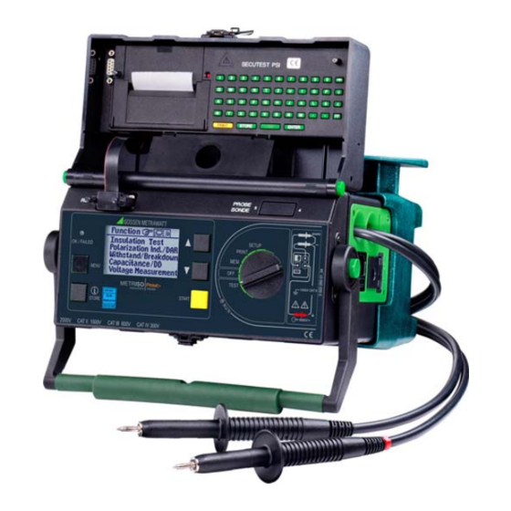
- Page 3 1 Function selector switch 16 Inlet plug for supply power with fuse compartment Switch positions: 17 Connector jack for guard cable (feature G1) SETUP: General device settings 18 Connection for automotive charging adapter J1 Print out measured values and reports 19 Device base Outside: With uptake for measurement cable, test probes and alligator clips Select data memory function...
- Page 4 High-Voltage Switching Pistol Retrofitting with a high-voltage module (feature B1 or B2) can only be performed by GMC-I Service GmbH. The high-voltage module is then controlled by MERISO PRIME+. 1 Inlet plug for high-voltage module supply power with fuse insert 2 Key switch for prevention of unauthorized start-up 3 Connection for external signal lamps (see chapter 3.2.3 on page 18) 4 High-voltage module ready for operation when signal lamp is lit up green...
- Page 5 PC Program WinProfi for communication with MERISO PRIME+ The free PC starter software WinProfi is used for communication with your MERISO PRIME+ test instrument. WinProfi* is available on our homepage with the following content and functions: • up-to-date test instrument software –...
-
Page 6: Table Of Contents
Contents Contents Page Page Applications ..................8 Performing Tests ................29 List of Available Features ...............9 Insulation (resistance) Test ............29 4.1.1 Setting Test Parameters ............30 Safety Features and Precautions ..........10 4.1.2 Starting the Test (U ) ...........31 Checklist for High-Voltage Tests ............11 4.1.3 Starting the Test (U ) ............31... - Page 7 Contents Contents Page Page Processing, Reorganizing and Deleting Data ......48 Appendix ..................64 Select Device under Test (DUT) ............ 48 11.1 Glossary ..................64 5.1.1 Entering Descriptions ............... 49 11.2 Minimum Display Values in Consideration of 5.1.2 Copying Descriptions ............... 50 Measuring Error ................
-
Page 8: Applications
Applications Notes Regarding SECUTEST PSI Operating Instructions In combination with the MERISO PRIME+, the SECUTEST PSI The MERISO PRIME+ insulation measuring instrument is in com- printer module is only used for printing out measured values and pliance with the following standards and regulations: for entering comments with the alphanumeric keypad. -
Page 9: List Of Available Features
List of Available Features Features Country version GB in- (user interface ter- language, nati- mains plug type) onal PROFITEST204HP/2.5kV none with (not with C1) PROFITEST204HV/5.4kV none with (not with C1) Set of batteries none with (not with B1, B2) DAkkS calibration none with certificate... -
Page 10: Safety Features And Precautions
Safety Features and Precautions The MERISO PRIME+ test instrument, and the • If only the batteries are to be charged (instrument is ready for PROFITEST204HP/2.5kV and PROFITEST204HV/5.4kV high operation in SETUP position), please ensure that the test in- voltage modules have been manufactured and tested in accor- strument cannot be used by unauthorized personnel during dance with the following safety regulations: the charging process. -
Page 11: Checklist For High-Voltage Tests
Safety Precautions for the Machine Under Test (recommended) Opening of Equipment / Repair The equipment may be opened only by authorized service per- Ð Review the circuit diagrams and make a note of all electrical circuits. sonnel to ensure the safe and correct operation of the equipment Ð... -
Page 12: Significance Of Symbols
Significance of Symbols 2.2.3 Symbols in the User Interface 2.2.1 Symbols on the Device High-voltage warning, The symbols on the device have the following meanings: Voltage at the test probe between 1000 and 5000 V Indicates EC conformity Warning concerning a source of danger, Voltage at the test probe Life endangering for the operator if the wiring dia- between 25 and 1000 V... -
Page 13: Symbols In The User Interface With Feature B1/B2
2.2.4 Symbols in the User Interface with Feature B1/B2 Precautions for the prevention of inadvertent start-up: High-voltage module ready to be switched • Multiple key operation: Before test voltage can be applied to the test probes by acti- vating the trigger at the high-voltage switching pistol, the START key must be pressed at the primary device. - Page 14 Attention! Attention High-Voltage! The vent slots in the bottom of the high-voltage module When the trigger at the high-voltage switching pistol is may not be covered! pulled to the first point of discernible mechanical resis- tance, the test probe is exposed. If the trigger is pulled beyond this point of mechanical re- sistance, high-voltage is applied to the test probe, as- Attention!
-
Page 15: Initial Start-Up
Initial Start-Up 3.1.1 Removing the Device Base and Inserting or Replacing the Battery Pack The MERISO PRIME+ test instrument is supplied with a base Please observe instructions included in this chapter if the device which serves as a compartment for storing test cables, the guard is to be retrofitted with a battery pack, or if the battery pack cable (feature G1), the test probes and the battery pack requires replacement. - Page 16 Ð Connect the two cables to each other and secure the connec- tion with the snap hooks. Ð Position the cable such that is cannot be pinched during sub- sequent assembly. Ð Carefully set the device onto the base as shown in the photo by grasping the handle with one hand, and guiding the bottom of the device into position with the other hand.
-
Page 17: Initial Start-Up With Feature B1/B2
Attention! Possible Danger of Use only the screws furnished with the device together Pinching! with washers. Longer screws may reduce creepage dis- tances or damage the device. If a battery pack (feature C1) has been installed and the device is not connected to the mains, the battery symbol appears at the display when the device is switched on, and the number of... -
Page 18: Indication Of Operating States
3.2.3 Indication of Operating States Signal Lamps at the High-Voltage Module Attention! All means of access to the danger zone must be closed The signal lamps integrated into the high-voltage module indicate when the high-voltage module is in the “standby” mode! two different operating states: The device must be sent to GMC-I Service GmbH in order to Green... -
Page 19: Mounting The Meriso Prime+ With Feature B1/B2 To The Trolley (Feature D1)
Mounting the MERISO PRIME+ with Feature B1/B2 to the Trolley (feature D1). Item Designation Qty. Order Number Base 3-117-193-01 Ð Set the complete unit consisting of test instrument and Cable uptake 3-326-653-01 high-voltage module onto the trolley’s platform (1) such that Handle clamp 3-326-652-01 the cover of the test instrument can still be opened. -
Page 20: Mains Connection
Mains Connection Attention! = 230 V If a connection via earthing contact outlet is not possible, L – N disconnect the mains from all sources of voltage before connecting the cables of the coupling socket via pick-up clips with the mains connections, as shown in the draw- ing. -
Page 21: User Interface
Ð Press the STORE key in order to query online help: User Interface Measuring and testing with the MERISO PRIME+ is quick and easy. The integrated user interface provides the operator with in- formation regarding required operating steps, operator errors, STORE measurement results and more for all measuring functions. -
Page 22: Setup
Setup 3.7.1 Adjusting Contrast and LCD Illumination Various basic settings can be selected for the test instrument with Contrast can be increased or decreased with this function. the selector switch in the SETUP position. LCD illumination can be switched on or off as well. SETUP SETUP Select Parameter... -
Page 23: Setting Date And Time
3.7.2 Setting Date and Time The test instrument’s internal clock can be set with this function. The clock continues to run after supply power has been discon- nected. Date and time are included in the test reports. Entries are made using the following formats: Date: DD.MM.YYYY (Day.Month.Year) -
Page 24: Beeper Settings
3.7.3 Beeper Settings The beeper can be completely deactivated or activated as indi- SETUP cated in the table below. Beeper Beeper Beeper for Beeper for deactivated activated measuring functions high-voltage • Beeper — — — upon key stroke • • Beeper upon good/ —... -
Page 25: Executing The Self-Test
3.7.4 Executing the Self-Test This function displays important device data first. If required, dis- play lamp and relay functions, as well as other options, can be tested automatically and results appear at the display. START SETUP Battery Voltage and LED Test START Select Self-Test Continue Test... -
Page 26: Downloading A Language Or A Software Update
3.7.5 Downloading a Language or a Software Update A Installing WinProfi to the PC and Starting the Program Ð Download the WinProfi software from our homepage: If you require a language other than one of those included with the instrument, it can be downloaded with the help of WinProfi* http://www.gossenmetrawatt.com (→... - Page 27 B Prerequisites for Software Update or Exchange of Data C Transmitting a Software Update to the Test Instrument Ð Find the interface to which the MERISO PRIME+ is con- nected. Ð PC: Select Update all from the update menu. Follow the instruc- tions which appear at the monitor.
- Page 28 D Organizing Report Data • Editing and transmitting report templates Ð Connect the test instrument directly via cable Z3241 with the Note Do not connect the PC to the PSI module. • Sending and receiving data • Printing out data •...
-
Page 29: Performing Tests
Performing Tests Insulation (resistance) Test Test voltage can be set between 100 V and 5,000 V for this test. Each of the following tests is automatically assigned to one cur- This voltage, as well as the allowable limit value for insulation rently available object number. -
Page 30: Setting Test Parameters
4.1.1 Setting Test Parameters The type of utilized test voltage can be selected here: Attention! • Fixed test voltage Do not touch the test probes during measurement! • Variable test voltage A direct voltage of up to 5000 V is present between the (e.g. -
Page 31: Starting The Test (Unom , Uvar )
4.1.2 Starting the Test (U Significance of Parameters with Variable and Fixed Test Voltage Test voltage U Test voltage in fixed steps (100/250/500 V, 1.00/1.50/2.00/2.50/5.00 kV) START Variable test voltage (100 V … 5.00 kV in 50 V steps) Test voltage Limit R Limit value for insulation resistance (If value stays below limit value: measurement failed) -
Page 32: Data Logger Function (Min Log)(As Of Firmware Version Ah)
4.1.4 Data logger function (min log)(as of firmware version AH) MENU Statistical analysis Select Parameter Press the CURSOR DOWN or CURSOR UP keys to return to the previous If you choose time parameter setting "min log" from the menu, LCD display. exactly 30 measured values are automatically stored during the selected test duration at time intervals between 4 seconds and 2 minutes. -
Page 33: Measurements With The Guard Cable (Feature G1)
4.1.5 Measurements with the Guard Cable (feature G1) The measurement of very high resistances necessitates extremely Note minimal measuring current and may be rendered problematic as a The following materials can be used as guard rings: alu- result of influences such as electromagnetic fields, humidity or minum foil, copper foil or metallic hose clamps. -
Page 34: High-Voltage Test With Feature B1/B2
High-Voltage Test with Feature B1/B2 b) Voltage Test The electrical equipment of the machine under test must Ð Set the key switch to the “I” position. withstand a test voltage of twice its own rated voltage value or • The green signal lamps must light up. 1000 V~ (whichever is greater) applied between the conductors of Ð... - Page 35 d) Power Failure Ð Press the START key. Attention High-Voltage! • The red signal lamps must light up. Touch neither the test probes nor the device under test Ð Set the key switch to the “0” position and wait at least 1 sec- during the high-voltage test! Life endangering high-voltage of up to 5.3 kV is present at the ond.
-
Page 36: Setting Test Parameters For High-Voltage Testing
4.2.2 Setting Test Parameters for High-Voltage Testing The following parameters can be set in the “standby” mode with illuminated green signal lamps: MENU Test v. AC-HV Select Parameter Max. test voltage, final value after T has elapsed AC.MAX. HP-2.5kV: 250 V … 2.50 kV Setting limits: HV-5.4kV: 650 V …... -
Page 37: High-Voltage Testing Sequence
4.2.3 High-Voltage Testing Sequence Ð Pull both triggers, but only pull the trigger at the high-voltage switching pistol up to the first point of mechanical resistance. Attention! The test probes are enabled. Before initializing any tests, and before enabling the test Ð... - Page 38 High-Voltage Test Saving Measured Values Aborting the Before Completion After the test sequence has been completed, the last measured The high-voltage test can be aborted prematurely at any time by and I values remain at the display. Results can be saved to releasing the trigger at the high-voltage switching pistol.
-
Page 39: Pulse Control Mode
4.2.4 Pulse Control Mode 4.2.5 Ending the High-voltage Test Ð Release the triggers at the high-voltage pistols. We recommend selecting the pulse control mode for troubleshooting purposes (arc-over pinpointing). Ð Press the MENU key. Interrupting current I is fixed to a value of approximately Ð... -
Page 40: Polarization Index Measurement
Polarization Index Measurement Absorption Index (DAR) – DC Charging Test A polarization index test is recommended for electrical machines. The absorption index test is part of the polarization index test. This procedure involves expanded testing of insulation resistance. Insulation resistance measurements are placed in relationship to DC measuring voltage from the MERISO PRIME+ is applied to one another after 30 and 60 seconds. -
Page 41: Setting Test Parameters
4.3.1 Setting Test Parameters 4.3.2 Starting the Test START MENU Select Parameter The two countdown timers (10:00 and 02:00) display remaining Set Value test time for each respective function. Significance of Parameters Nominal insulation voltage ins[nom] 100/250/500 V, 1.00/1.50/2.00/2.50/5.00 kV PI(t2/t1) Polarization index PI is the relationship between insula- tion resistance values measured after 1 minute PI(t1),... -
Page 42: Breakdown Voltage
Breakdown Voltage Step-Voltage Test – DC Charging Test Voltage is increased up to the limit value (selected maximum test voltage) over the selected rise time during the breakdown voltage TEST test. If voltage breakdown occurs before this value is reached, breakdown voltage U is displayed. -
Page 43: Setting Test Parameters
4.4.1 Setting Test Parameters 4.4.2 Starting the Test START Set Parameters Significance of Parameters with Variable and Fixed Test Voltage STORE Test voltage U Test voltage in fixed steps Press briefly: Save results (100/250/500 V, 1.00/1.50/2.00/2.50/5.00 kV) Variable test voltage (100 V … 5.00 kV) Press &... -
Page 44: Capacitance Measurement And Determination Of Dielectric Discharge (Optional)
Capacitance Measurement and Determination of Dielectric Discharge (optional) Capacitance measurement is performed with adjustable test volt- age by charging with constant current. The measurement is per- formed with automatic range selection. One of the nominal test voltages (U ), or a freely selectable test voltage (U ) can be TEST used. -
Page 45: Starting The Test
4.5.2 Starting the Test START After capacitance has been determined, the instrument automati- cally continues with dielectric discharge testing. This takes about 30 minutes. However, the measurement can be aborted at any time by pressing the MENU key. Only capacitance is displayed in this case. -
Page 46: Voltage Measurement (Protection Against Residual Voltage)
Voltage Measurement (protection against residual voltage) EN 60204 requires that voltages in excess of 60 V occurring at all When the display is “frozen”, voltage measurement is not started accessible machine components during operation must drop to a again until: residual voltage value of 60 V or less within a period of 5 seconds •... -
Page 47: Setting Test Parameters
4.6.1 Setting Test Parameters 4.6.2 Starting the Test The discharge time during which the voltage value must drop to a non-hazardous value of less than 60 V can be specified as a limit START value between 1.0 and 9.00 seconds. The following message appears in order to indicate that the limit has been reached: “residual voltage less than 60 V!”. -
Page 48: Processing, Reorganizing And Deleting Data
Processing, Reorganizing and Deleting Data Previously stored data and data records can be processed with Select Device under Test (DUT) the selector switch in the data management position. The following functions are available: • DUT data An object number can be assigned here, and measurements can be saved with reference to the selected number. -
Page 49: Entering Descriptions
5.1.1 Entering Descriptions – Entry using keys at the MERISO PRIME+ Select Letter, Number or Character. MENU STORE Move Cursor Left Description START Description: A description can be entered here for an object, which is displayed and subsequently printed out when the respective Move Cursor Right object is selected. -
Page 50: Copying Descriptions
5.1.2 Copying Descriptions Processing Data (checking measured values) Measured values can be checked with this function, and individ- Ð Select the object with the description to be copied and press ual measurements can be deleted if desired. the MENU key 3 times. Ð... -
Page 51: Data Reorganization
Data Reorganization 5.3.1 Deleting Already Printed Data print-out is generated including all DUTs for which measured data are stored to memory. Data for individual DUTs which have already been printed out in report form, or DUTs which have been entered although no mea- 5.3.2 Memory Test sured values have been saved for them yet, can be deleted here if The memory module is checked for errors with this function. -
Page 52: Clearing The Memory
Clearing the Memory This command deletes data records previously saved to memory A security acknowledgement must be entered before memory is for all DUTs. Full memory capacity is made available by means of cleared. Final deletion is initialized with the i/STORE key. this procedure. -
Page 53: Printing Test Results
Printing Test Results The test instrument’s report functions can be activated with the selector switch in the printer position. The following functions are available: • Print out values at the PSI module (feature I1): Measured values for a selected object can be printed out at the utilized printer module via the serial interface. -
Page 54: Characteristic Values
Characteristic Values Insulation Test Voltage Nominal Values, Variable Nominal Current Intrinsic Uncertainty Standards DIN EN 61557-1:2007 Test Voltage Test Voltage ≥ 1.0 mA DIN EN 61557-2:2008 100 V, 250 V, 500 V, 1.00 kV 0 ... +25% rdg. ≥ 0.4 mA VDE regulations VDE 0413 Part 1:2007 1.50 kV, 2.00 kV, 2.50 kV... - Page 55 Capacitance Measurement Power Supply PROFITEST 204HP/HV … … Line voltage 207 V 253 V / 49 Hz 61 Hz Display Measuring Test Voltage Intrinsic Uncertainty Measuring Range Range Uncertainty Power consumption PROFITEST 204HP-2.5kV: max. 700 VA ± (10% rdg. + 5 d) ±...
- Page 56 Electromagnetic Compatibility (EMC) MERISO PRIME+ Mechanical Design MERISO PRIME+ Product standards EN 61326-1:2006 Display Multiple display with dot matrix 128 x 64 pixels Dimensions W x H x D: Interference Emission 255 mm x 133 mm x 240 mm EN 55022 Class A Weight approx.
-
Page 57: Data Interfaces
Data Interfaces RS 232 Serial Interface All MERISO PRIME+ control functions can also be remote con- trolled via this interface. Signal and display values can be read out The data interface socket connector (4) is used to connect the as well. SECUTEST PSI module (feature I1), a barcode scanner (acces- A description of the interface protocol, as well as commands and sory no. -
Page 58: Displays And Error Messages - Causes - Remedies
Displays and Error Messages – Causes – Remedies Displays and Error Messages Meaning / Cause Remedy MERISO PRIME+ Test Sequence Countdown runs here until residual voltage is less than 60 V. All-clear after an insulation test: voltage at test probes less than 25 or 60 V depending upon measuring function The test has been passed. - Page 59 Displays and Error Messages Meaning / Cause Remedy An error has occurred while saving data to memory. Save data to a PC and then clear the memory. See text at the display. Press the START key to repair. Memory in no longer able to save new measurement data. Save data to a PC and then clear the memory.
- Page 60 Displays and Error Messages Meaning / Cause Remedy The measurement has been saved to memory. MERISO PRIME+(with feature B1 or B2) The displayed high-voltage module has been detected. Turn device on with key switch. The displayed high-voltage module has been detected. Turn device on with key switch.
-
Page 61: Maintenance
Maintenance 10.2 Testing of Rechargeable Batteries Check the batteries for leakage or damage at short regular inter- 10.1 Replacing the Mains Fuse vals, and after long periods of storage. If damage or leakage has occurred, carefully and completely clean the electrolyte from the instrument with a damp cloth, and replace the batteries with a new battery pack (accessory no. -
Page 62: Measurement Cables
10.4 Measurement Cables 10.6 Replacing Bulbs in the External Signal Lamps (Feature F1) Inspect the measurement cables for mechanical damage at regu- lar intervals. Attention! Before replacing bulbs in the external signal lamps, dis- connect them from the connector terminals at the test Attention! instrument. -
Page 63: Recalibration
10.9 Device Return and Environmentally Compatible Disposal Note The instrument is a category 9 product (monitoring and control After updating the software, reinstall the desired lan- instrument) in accordance with ElektroG (German Electrical and guage to the test instrument as well, even if the language Electronic Device Law). -
Page 64: Appendix
Appendix 11.2 Minimum Display Values in Consideration of Measuring Error 11.1 Glossary Table for determining minimal display values for insulation resis- tance in consideration of the instrument’s measuring error: Abbreviation Meaning Absorption Ratio: Ratio between insulation resistance values measured after 30 and 60 seconds Dielectric Discharge Limit Value Minimum Display... -
Page 65: Voltage At Device Under Test During Insulation Resistance Test
11.3 Voltage at Device Under Test During Insulation Resistance Test Test voltage U at the device under test depending upon its resistance R at nominal voltage 100, 500, 1000, 2400 and 1000 5000 V: = 1000 V = 100 V /MΩ... -
Page 66: Index
11.4 Index Fuses Safety measures Data ....... 55 Control circuits ..... . 11 Beeper Replacement . -
Page 67: Repair And Replacement Parts Service, Calibration Center And Rental Instrument Service
Repair and Replacement Parts Service, Competent Partner GMC-I Messtechnik GmbH is certified in accordance with Calibration Center* and Rental Instrument Service DIN EN ISO 9001:2008. When you need service, please contact: Our DAkkS calibration laboratory is accredited by the Deutsche Akkreditierungsstelle GmbH (National accreditation body for the Federal Republic of Germany) in accordance with DIN EN ISO/IEC GMC-I Service GmbH... -
Page 68: Product Support
Product Support When you need service, please contact: GMC-I Messtechnik GmbH Product Support Hotline Phone: +49 911 8602-0 Fax: +49 911 8602-709 e-mail support@gossenmetrawatt.com Edited in Germany • Subject to change without notice • A pdf version is available on the internet. Phone +49 911 8602-111 GMC-I Messtechnik GmbH +49 911 8602-777...
Need help?
Do you have a question about the METRISO PRIME+ and is the answer not in the manual?
Questions and answers