Table of Contents
Advertisement
Quick Links
Advertisement
Table of Contents

Related Manuals for Gossen MetraWatt GEOHM 5


Summary of Contents for Gossen MetraWatt GEOHM 5
- Page 1 User Manual GEOHM 5 Earth Tester 3-349-418-03 3/12.20...
- Page 2 WEEE mark can be accessed on the Internet at www.gossenmetrawatt.com by entering the search term „WEEE“. © 2009 Gossen Metrawatt GmbH No part of this publication may be reproduced or utilized in any form or by any means without permission in writing from Gossen Metrawatt GmbH.
-
Page 3: Table Of Contents
GEOHM 5 Table of contents Introduction ......................4 General description ................... 4 Warnings ......................4 General settings (first use) ................5 List of parameters measured by the Earth Tester ..........6 Standards applied ..................... 6 Instrument description ..................7 Instrument Casing ..................... 7 Front panel ...................... -
Page 4: Introduction
GEOHM 5 Introduction 1 Introduction We are very pleased to offer a high quality, professional grade test instrument, for carrying out four wire Earth Resistance measurements, as well as specific ground resistance measurements on which the estimation of earthing quality is based. The equipment was designed and produced based on many years experience of producing and dealing with Earth Resistance and Electric installation test equipment. -
Page 5: General Settings (First Use)
GEOHM 5 Introduction 1.3 General settings (first use) There is usually voltage or current noise present on the earthing system under test, caused by mains voltage somewhere in the near or far vicinity. Mains voltage frequency is different in different countries (50 Hz in European countries etc., 60 Hz in the United States etc.). -
Page 6: List Of Parameters Measured By The Earth Tester
GEOHM 5 Introduction Press START key to confirm measuring algorithm. The instrument is ready for regular measurements. Note: In general it is recommended to use the ‘Normal’ measuring algorithm because of the instrument’s high intrinsic noise immunity. If the results are still unstable further improvements can be achieved by averaging eg. -
Page 7: Instrument Description
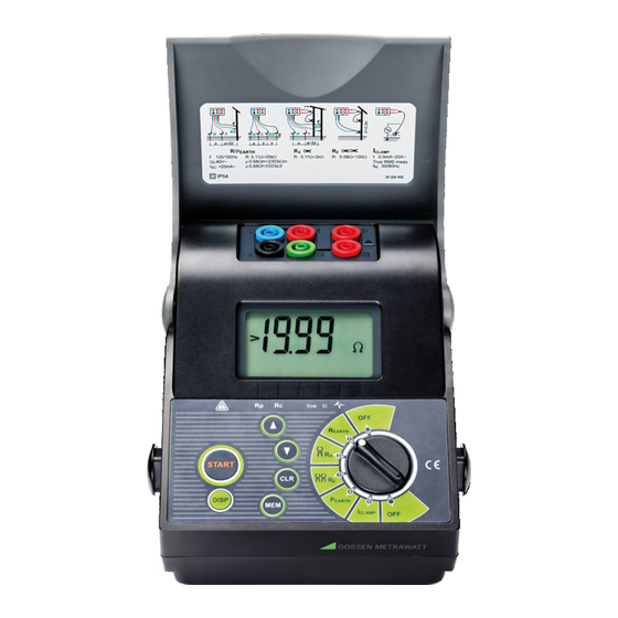
GEOHM 5 Instrument description 2 Instrument description 2.1 Instrument Casing The instrument is housed in a plastic casing, which maintains the protection class defined in the general specifications. The casing consists of a main section, which includes the operator's panel and connectors and of a moveable cover. - Page 8 GEOHM 5 Instrument description Legend: Custom designed LCD. CURSOR up key to: Increment storage MEM code. View previous result Set the instrument to general settings Earth resistivity function: Increment the distance »a« between test rods START key to: ...
-
Page 9: Connector Panel
GEOHM 5 Instrument description 2.3 Connector panel blue E-Clip 2 E-Clip 1 black black Figure 2. Connector panel Legend: Test terminals: Blue – test terminal H Black – test terminal E Red - test terminal S Green - test terminal ES... -
Page 10: Instrument Messages
GEOHM 5 Instrument description Legend: Plastic housing. Screw (4 pieces) to fix the battery cover. Battery compartment cover. Battery cover warnings. Trade mark label. Plastic holder for carrying strap 2.5 Instrument Messages Messages are generated on the LCD using special symbols and numeric segment combinations. -
Page 11: Earth Resistance
GEOHM 5 Instrument description General settings – selection of frequency General settings – selection of unit in Earth Resistivity measurement t ┌┐, t ┌─┐ General settings – selection of measuring algorithm Batteries are too weak – replace the batteries. *Reset of the instrument (erased memories). - Page 12 GEOHM 5 Instrument description Step 1 Connect the test leads to the instrument and to the object under test in accordance with the figures below. Figure 5. Connection of standard 20 m long test leads Figure 6. Connection of optional 50 m long test leads...
- Page 13 GEOHM 5 Instrument description Step 2 Set the function switch to R position, the following menu will be displayed: EARTH Figure 7. Earth Resistance initial menu Step 3 Press START key and view the test result. (If you want to perform more than one measurement press the START key and keep it pressed until the result has stabilized, then release the key.
-
Page 14: Standard Four-Lead Test Method In Combination With Sensitive Test Clamp
GEOHM 5 Instrument description 2.6.2 Standard four-lead test method in combination with sensitive test clamp Measuring selective earth resistance (test clamp E-Clip 1) If several earthing electrodes are connected in parallel (see figure 8), then it is very important to know the quality of each individual electrode. This is especially important... - Page 15 GEOHM 5 Instrument description Step 2 “ position, the following menu will be displayed. Set function switch to ” Figure 9 Earth Resistance initial menu Step 3 Press START key and view the test result. (If you want to perform more than one measurement press the START key and keep it pressed until the result has stabilized, than release the key.
-
Page 16: Earth Resistance Measurement With Two Test Clamps
GEOHM 5 Instrument description If noise current higher than approx. 2,1 A is present in the clamp loop, a cursor mark pointing to the “ ” (noise) symbol will be displayed, indicating that the test result may not be correct! The value of noise current may be also measured in the CURRENT function, see chapter 2.8. - Page 17 GEOHM 5 Instrument description Step 1 Connect test clamps to the instrument and to the object under test in accordance with the figure below (test clamps must be at least 30 cm apart). Figure 11.. Connection of two test clamps Step 2 ...
- Page 18 GEOHM 5 Instrument description Notes! If the test result is out of the measurement range (e.g. open test leads), >99,9 message will be displayed! If the current, measured with the sensitive test clamp, is lower than 0,5 mA, the...
-
Page 19: Specific Earth Resistance
GEOHM 5 Instrument description 2.7 Specific Earth Resistance To ensure accurate calculations, it is advisable to measure the Earth Resistivity, when defining the parameters of the earthing system (required length and surface of earth electrodes, most appropriate depth for installing the earthing system etc.). - Page 20 GEOHM 5 Instrument description Step 2 Set function switch to position, the following menu will be displayed: EARTH Figure 14. Earth Resistivity initial menu Step 3 Set the distance “a” between the test rods. The distance must be the same as the one used in the practical measurement, otherwise the test result will not be correct.
- Page 21 GEOHM 5 Instrument description Store displayed result for documentation purposes, see instructions how to use the memory in chapter 3.1.1. Repeat the measurement by placing the test probes in different directions and with different distances between them. Check or correct the distance “a” entered into the instrument before every measurement.
-
Page 22: Current (True Rms)
GEOHM 5 Instrument description 2.8 Current (True RMS) In complex earthing systems with numerous electrodes connected in parallel or other systems connected to the earthing system, large leakage currents can be present. The shape of the measured current is usually a non-sinusoidal wave. The shape is distorted by various non-linear sources. - Page 23 GEOHM 5 Instrument description Figure 18. Typical connection of sensitive test clamp (E-CLIP 1) when searching for installation faults Step 3 Measurement commences (constant measurement), the result is continuously displayed. Measurement stops, last result will stay displayed. Store the displayed result for documentation purpose, see instructions in chapter...
-
Page 24: Memory And Other Operations
GEOHM 5 Memory and other operations 3 Memory and other operations 3.1 Memory The memory for the storage of measurement results has a stacking group organization. The operator can organize up to 250 memory locations. Each memory location can stack any measured result. In ‘storing result’ mode the operator selects a MEM code and then the result is stacked together with all its parameters into the selected memory location. -
Page 25: Storing Of Test Results
GEOHM 5 Memory and other operations Stored Results and Parameters for each function code The following is a list of results, subresults, and parameters stored for each function code (FC). Function FC Stored data and Function FC Stored data and... -
Page 26: Recalling Of Stored Results
GEOHM 5 Memory and other operations Main result, potential subresults and potential function parameters as well as Function identification number (see the figure below) are stored, whenever the “MEM” procedure is used. Further test results (regardless of test function) can be stored under the same MEM code. - Page 27 GEOHM 5 Memory and other operations MEM code will stop flashing. Function identification number (FC) will follow the set MEM code and then the last stored result will appear. Check subresult and function parameter by pressing the DISP key.
-
Page 28: Erasing Stored Results
GEOHM 5 Memory and other operations 3.1.3 Erasing stored results Two modes of erasing the stored results are available namely: All stored results can be erased in one step The last stored result, can be erased How to erase all stored results Press and hold CLR key until Clr MEM / ALL MEM messages starts to alternate (approx. -
Page 29: Rs 232 Communication
3.2 RS 232 communication Stored results can be transferred to PC, where final test reports will be formed. The PC Software LINK Z591D-Geohm 5 is needed for this operation. How to transfer stored results Install PC LINK Z591D-Geohm 5 on PC ... -
Page 30: Reset Of The Instrument
GEOHM 5 Memory and other operations 3.3 Reset of the instrument If any malfunction is experienced when dealing with the Earth Tester, it is advisable that RESET of the instrument to be carried out. In this instance all parameters will revert to their initial values, see the table below. -
Page 31: Maintenance
GEOHM 5 Maintenance 4 Maintenance 4.1 Batteries The battery symbol - on the upper left corner of the LCD indicates a low battery state (Ubat < 4.2 V). If a low battery state is indicated, the batteries must be replaced to ensure accurate measurements. -
Page 32: Cleaning
GEOHM 5 Maintenance To ensure that stored data is not lost the following procedure must be adhered to when replacing the batteries: Disconnect all cables Switch OFF the instrument. Replace the batteries within one minute. Switch ON the instrument, if Clr mem message will not be displayed, indicating stored data has not been erased. -
Page 33: Service
GEOHM 5 Maintenance We are pleased to perform DKD or factory calibrations for you in our calibration laboratory. Please visit our website at www.gossenmetrawatt.com (® Services ® DKD Calibration Center or ® FAQs ® Calibration questions and answers). By having your measuring instrument calibrated regularly, you fulfill the requirements of a quality management system per DIN EN ISO 9001. -
Page 34: Technical Specification
GEOHM 5 Technical specification 5 Technical specification 5.1 Measurement functions Earth Resistance four–lead method Measurement range RE (0,11 19,99k) Accuracy Display range () Resolution () 0,00 19,99 0,01 (2 % rdg. + 3 D) 20,0 199,9 200 ... - Page 35 GEOHM 5 Technical specification Earth Resistance using two clamps Accuracy* Display range RE () Resolution () 0,0 19,9 (10 % rdg. +2 D) 20 100 (20 % rdg.) *Distance between test clamps >30 cm Additional error at lowest noise curr. where noise curr. symbol is already displayed (10 % of r.
-
Page 36: General Characteristics
GEOHM 5 Technical specification Current (True RMS) Display range I (A) Resolution (A) Accuracy 0,0 m 99,9 m (5 % rdg. + 3 D) 0,1 m 100 m 999 m (5 % rdg.) 1,00 9,99 0,01 10,0 19,9 10 ... -
Page 37: Standard Accessories
GEOHM 5 6 Standard accessories 1 Earth tester 1 Case (stackable, lightweight but rugged plastic box) 1 Neck strap 1 Set batteries 4 Earth spikes 4 Measurement cables 1 Set operating instructions 6.1 Optional accessories E-Clip 1 Clip-On Meter Measuring range: 1 mA to 1200 A Measuring category: 600 V CAT III Max. -
Page 38: Repair And Replacement Parts Service, Calibration Center And Rental
GEOHM 5 7 Repair and Replacement Parts Service, Calibration Center and Rental Instrument Service If required please contact: GMC-I Service GmbH Service Center Beuthener Straße 41 90471 Nürnberg, Germany Phone: +49 911 817718-0 Fax: +49 911 817718-253 e-mail: service@gossenmetrawatt.com www.gmci-service.com This address is only valid in Germany. - Page 39 GEOHM 5...
- Page 40 GEOHM 5 Phone: +49 911 8602-111 Gossen Metrawatt GmbH Fax: +49 911 8602-777 Südwestpark 15 e-mail: info@gossenmetrawatt.com 90449 Nürnberg, Germany www.gossenmetrawatt.com...
Need help?
Do you have a question about the GEOHM 5 and is the answer not in the manual?
Questions and answers