Advertisement
Quick Links
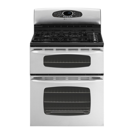
Double Oven Electric Range
MER6875BA*
• Due to possibility of personal injury or property damage, always contact an authorized technician for servicing or
repair of this unit.
• Refer to Service Manual 16023416 for detailed installation, operating, testing, troubleshooting, and disassembly
instructions.
All safety information must be followed as provided in Service Manual 16023416.
To avoid risk of electrical shock, personal injury or death; disconnect power to range before servicing, unless
testing requires power.
* Rating of 208 VAC is approximately 80% of 240 VAC value.
July 2006
©2006 Maytag Services
!
!
Sears Models
Power Source @ 240 V (208 V)
Electrical rating
Frequency
Element Wattage @ 240 V
Ribbon element, 6 inch, warmer
Ribbon element, 6"
Ribbon element, dual, 9"
Ribbon element, triple, 12"
Convection Element
Oven Wattage @ 240 V
Upper Bake 4 pass
Lower Bake 4 pass
Upper Broil 4 pass
Lower Broil 4 pass
Convection
Oven Interior Dimensions in. (cm)
Height
Width
Depth
Product Exterior Dimensions in. (cm)
Height overall
Width
Depth oven door closed w/out handle
Features
Frameless glass door w/window
Interior oven light
Three oven racks in lower oven
One oven rack in upper oven
Automatic oven door latch
Convection oven
Cooktop warmer/simmer element
Weight lbs. (kg)
Crated
Technical Information
—
CAUTION
WARNING
MER6875BA*
12.9 kW (9.7 kW)
60 Hz
100 W*
1,200* (2)
2,400/1,100*
2,700/2,000/1,000*
1,850*
1,800*
2,600*
2,200*
3,000*
1,850*
16 1/2
(42)
23
(58)
17 1/2
(46)
46 3/4
(118)
29 7/8
(76)
26 1/8
(66)
Yes
Yes
Yes
Yes
Yes
Yes
Yes
235
(107)
1
16027361
Advertisement

Related Manuals for Maytag MER6875BA Series


Summary of Contents for Maytag MER6875BA Series
- Page 1 Three oven racks in lower oven One oven rack in upper oven Automatic oven door latch Convection oven Cooktop warmer/simmer element Weight lbs. (kg) Crated (107) * Rating of 208 VAC is approximately 80% of 240 VAC value. July 2006 16027361 ©2006 Maytag Services...
-
Page 2: Component Testing Procedures
Connect Volt-ohms meter to Approximate element H1 and H2. Time On Time Off Measure the following for voltages at MED (4-5) LO, MED, HI: 100% H1 to H2..........240 VAC. If not, replace switch. 16027361 July 2006 ©2006 Maytag Services... - Page 3 240 VAC. Convection motor, Measure voltage........120 VAC. 2-speed Remove wires, check resistance....Approximately 30 Ω. Check motor windings to ground ....No continuity. Motor, hi-speed........Approximately 1200 RPM. Motor, low-speed ........Approximately 900 RPM. July 2006 16027361 ©2006 Maytag Services...
-
Page 4: Control Testing Procedures
Hold Clock pad for 3 to 5 seconds to disable All pad inputs are disabled except Sabbath mode. CANCEL and CLOCK pads. This mode disables the normal 12- hour shutoff to allow operation of the bake mode for a maximum of 72 hours. 16027361 July 2006 ©2006 Maytag Services... - Page 5 Upper Broil 5 & 17 Continuity Timer 1 4 & 16 Continuity Toast 7 & 8 Continuity Warm Zone 4 & 6 Continuity Warm Zone 4 & 17 Continuity Warm Zone 6 & 17 Continuity July 2006 16027361 ©2006 Maytag Services...
- Page 6 (provides a "quick preheat"). *During preheat cycle, broil element is used at 10% when lower oven is active. INDEX - OFF - CYCLING - ON OR OFF (DETERMINED BY USER INPUT) 16027361 July 2006 ©2006 Maytag Services...
-
Page 7: "Quick Test" Mode For Electronic Range Control
Diagnostic Code Display Mode may be activated at power-up by pressing and holding the AUTOSET pad for 3 to 5 seconds. Diagnostic Code Display Mode may be accessed only when applying power to the control. July 2006 16027361 ©2006 Maytag Services... - Page 8 Unlock switch not closed LOCK flashes Disables Clean and Lockout functions 9d31 Latch both locked and unlocked LOCK flashes Disables Clean and Lockout functions 9d32 Latch both locked and unlocked LOCK flashes Disables Clean and Lockout functions 16027361 July 2006 ©2006 Maytag Services...
- Page 9 If the control is in a known good lock position and the unlock switch becomes faulted: • The control will not fault. • After the function is canceled and unlock is attempted, the control will attempt to unlock the latch according to • the procedures in these notes. July 2006 16027361 ©2006 Maytag Services...
-
Page 10: Wiring Diagram And Schematic
Wiring Diagram and Schematic WARNING To avoid risk of electrical shock, personal injury or death; disconnect power to range before servicing, unless testing requires power. Wiring Diagram 16027361 July 2006 ©2006 Maytag Services... - Page 11 Wiring Diagram and Schematic WARNING To avoid risk of electrical shock, personal injury or death; disconnect power to range before servicing, unless testing requires power. Schematic (Control Circuits) July 2006 16027361 ©2006 Maytag Services...
Need help?
Do you have a question about the MER6875BA Series and is the answer not in the manual?
Questions and answers