Table of Contents
Advertisement
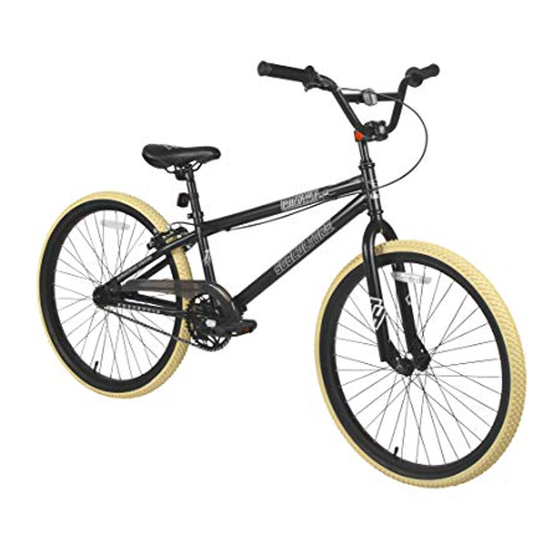
12" – 24" BMX
THIS MANUAL CONTAINS IMPORTANT SAFETY, PERFORMANCE AND MAINTENANCE INFORMATION. READ THE MANUAL BEFORE TAKING YOUR FIRST
RIDE ON YOUR NEW BICYCLE, AND KEEP THE MANUAL HANDY OF FUTURE REFERENCE.
NOTE: Illustrations in this Manual are for reference purposes only and may not reflect the exact appearance of the actual product. Specifications are subject to change without notice.
OWNER'S
MANUAL
DO NOT return this item to the store.
Questions or comments?
1-800-288-1560
Advertisement
Table of Contents

Related Manuals for Dynacraft BMX


Summary of Contents for Dynacraft BMX
- Page 1 OWNER’S MANUAL 12” – 24” BMX THIS MANUAL CONTAINS IMPORTANT SAFETY, PERFORMANCE AND MAINTENANCE INFORMATION. READ THE MANUAL BEFORE TAKING YOUR FIRST RIDE ON YOUR NEW BICYCLE, AND KEEP THE MANUAL HANDY OF FUTURE REFERENCE. DO NOT return this item to the store.
- Page 2 If you are not comfortable, or lack the skills or tools to assemble the bicycle yourself, you should take it to a qualified mechanic at a bicycle shop. Additionally, you can write or call us concerning missing parts or assembly questions. Dynacraft 1-800-551-0032 89 South Kelly Road, American Canyon, CA 94503 www.dynacraftwheels.com...
- Page 3 HELMETS SAVE LIVES! WARNING: Always wear a properly fitted helmet when you ride your bicycle. Do not ride at night. Avoid riding in wet conditions. Incorrect fitting Correct fitting Forehead is exposed and vulnerable Make sure your helmet covers to serious injury. your forehead.
-
Page 4: About This Manual
Dynacraft shall not have any responsibility for any breakdown of the bicycle, its components or rider injuries that occur during such use. -
Page 5: Table Of Contents
CONTENTS CONTENTS A ABOUT YOUR BIKE ......5 A ABOUT YOUR BIKE ......6 Model/Serial number Identification Model/Serial Number Identification Customer service... - Page 6 11 Tire Inflation 12 Tire inflation 13 Reflectors 12 Reflectors 13 Pegs 14 Pegs 15 Streamers, Pads & Bags 14 Streamers, Pads and Bags 15 Handlebar Accessories 16 Handlebar Accessories D BICYCLE ADJUSTMENTS ......28 D BICYCLE ADJUSTMENTS .
-
Page 7: A About Your Bike
MODEL/SERIAL NUMBER IDENTIFICATION Each Dynacraft bicycle has a serial number stamped into the frame. The serial number can be found on the bottom of the crank housing as shown (see Figure 1). The model number is found on a sticker on the frame at the bottom of the seat tube. - Page 8 BEFORE YOU RIDE BEFORE YOU RIDE PARTS/TOOLS LISTS Tools Required 1 Frame 2 Brake Lever 3 Handlebar 4 Grip 5 Front Reflector 6 Stem 7 Headset 8 Head Tube 9 Front Brake 10 Brake Pad 1 Standard Phillips Head 11 Fork Screwdriver 12 Tire 2 Adjustable Wrench...
- Page 9 FRAME SIZING When selecting a new bicycle, the correct choice of frame size is a very important safety consideration. To determine the correct size bicycle for the rider: • Straddle the assembled bicycle with feet shoulder width apart and flat on the ground •...
- Page 10 Most traffic regulations apply to bike riders as well as automobile operators. 9. ALWAYS RIDE ALONE. NEVER CARRY OTHER RIDERS. This is dangerous and makes the bike harder to control. The bicycles distributed by Dynacraft BSC, Inc. are intended for one rider only.
- Page 11 10. ALWAYS BE ALERT. BE ALERT - BE ALERT - pedestrians have the right of way. when riding near parked cars - ride far enough away from the cars so that you won’t get hit if someone opens the car door. 11.
-
Page 12: Night Riding
NIGHT RIDING Riding a bicycle at night is much more dangerous than riding during the day. A bicyclist is very difficult for motorists and pedestrians to see. Therefore, children should never ride at dawn, at dusk or at night. Adults who choose to accept the greatly increased risk of riding at dawn, at dusk or at night need to take extra care both riding and choosing specialized equipment which helps reduce that risk. -
Page 13: Safety Checklist
SAFETY CHECKLIST 4. WHEELS AND TIRES • Ensure tires are inflated to within the Before every ride, it is important to carry out the following maximum recommended limit as safety checks: (For information and instructions on displayed on the tire sidewall. performing specific equipment checks, locate the relevant •... -
Page 14: Bicycle Assembly
BICYCLE ASSEMBLY GETTING STARTED Open the box and check that all parts are present. You can check against the list on page 6. If any parts are missing or damaged, or if you have any trouble with the assembly, don’t return to the store. Call 1-800-551-0032 We strongly recommend reading the manual before beginning. -
Page 15: Pedals
1. PEDALS WARNING: Attachment of an incorrect pedal into a crank arm will cause irreparable damage. Unless the shoulder of the pedal spindle is tight to the face of the crank arm, the pedal may back out causing serious injury or death. Make it tight so the shoulder is in complete contact with the surface of the crank arm. -
Page 16: Seat
2. SEAT WARNING: Seatpost The seatpost must be inserted far enough so that the minimum insertion marks cannot be seen. Seat tube Add some white grease to the inside of the seat tube, and slide the seatpost into the bicycle. Make sure that the minimum insertion mark is completely covered and that the seat is pointing forward in alignment with the bicycle. -
Page 17: Testing Seat Clamp And Post Clamp Tightness
3. TESTING SEAT CLAMP AND POST CLAMP TIGHTNESS After installing the seatpost into the bicycle and tightening either the quick release clamp or the standard clamp, test the tightness of the saddle. Hold the saddle firmly with both hands and try to move it side to side. The seatpost should not move at all. The seatpost and saddle also should not move when the rider is seated. -
Page 18: Testing Handlebar And Stem Tightness
WARNING: Do not over tighten the stem bolt. Over tightening the stem bolt can damage the steering system and cause a loss of control. If necessary re-adjust the handlebar and tighten the handlebar clamp nut. WARNING: If the handlebar clamp is not tight enough, the handlebar can slip in the stem. -
Page 19: Front Wheel
6. FRONT WHEEL WARNING: It is very important to check the front wheel connection to the bicycle. Failure to properly tighten may cause the front wheel to dislodge, causing serious injury or death. Check the side of your tire to see if there is an arrow indicating direction. If an arrow is present, it should point forward. -
Page 20: Brakes
7. BRAKES WARNING: When assembling or adjusting the brakes, make sure the cable anchor nut is tight. Failure to securely tighten the nut could result in brake failure and personal injury. (See Figure 1.) Cable anchor 7A. Side Pull Brakes Brake cable Loosen the cable anchor nut and pull the brake cable through it. - Page 21 8. TESTING BRAKE FUNCTIONS For detailed instructions on brake adjustments, please see page 27. To test the function of the front hand brake, lift the front of the bike and spin the wheel. The wheel should not rub on the brake pads. Next, squeeze the brake lever and take note of the brake pads contacting the side of the wheel.
-
Page 22: Rotor Assembly
9. ROTOR ASSEMBLY To assemble the brakes on a gyro equipped bike, start by inserting the two loose ends of the rear brake cable (which comes from the right side brake lever) through the handlebar and threading them into the upper detangler plate. - Page 23 On a gyro equipped bike you need to Brake Lever Nipple Ferrule hook up the left-side brake lever cable, which controls the front brake. Begin by loosening the anchor nut on the front brake. Take the loose cable on the opposite end (the end which goes into the brake lever on the handlebar), Locking Cable...
-
Page 24: Training Wheels
10. TRAINING WHEELS To attach the training wheels to the frame, begin on one side by removing only the outer axle nut. Position the square alignment tab so that the notch on the tab fits into the corresponding slot on the frame. (See Figure 2.) Place the training wheel leg onto the axle and secure with the axle nut that was previously removed. -
Page 25: Tire Inflation
11. TIRE INFLATION WARNING: Tires must be properly inflated before riding. Never exceed the maximum pressure (PSI) that is listed on the side of the tire. WARNING: Be sure to check the edge (bead) of both tires are evenly seated the entire way around on both sides of the tire. -
Page 26: Reflectors
12. REFLECTORS Reflectors are pre-installed on your bicycle on the pedals, wheels, seatpost, and handlebars. Ensure that the handlebar reflector is pointing straight forward. Use a Phillips head screwdriver to loosen and adjust before re-tightening. Position the rear reflector so that it points straight backwards. -
Page 27: Pegs
13. PEGS To install pegs, begin by hand threading the pegs onto the axle. (See Figure 1.) Use a long screwdriver through the hole in the peg as leverage to tighten the peg fully on the axle. (See Figure 2.) 14. -
Page 28: D Bicycle Adjustments
BICYCLE ADJUSTMENTS SEAT ADJUSTMENT You can adjust the up and down tilt of your seat as well as the forward Closed and back position by loosening the seatpost hardware at the bottom of Open your seat. (See Figure 1.) Be careful not to loosen them all the way so that the nut comes off on either side. - Page 29 BICYCLE ADJUSTMENTS STEM ADJUSTMENT To raise or lower your stem, use an adjustable wrench or Allen wrench on the stem bolt to loosen the stem. (See Minimum SEAT ADJUSTMENT insertion Figure 1.) Do not remove this bolt completely, as the stem mark wedge may fall inside your frame.
- Page 30 STEM ADJUSTMENT HANDLEBAR ADJUSTMENT To adjust the handlebars forward and backwards, loosen the stem bolt or To raise or lower your stem, use an adjustable wrench or Allen wrench on the bolts. Your bike may have one (see Figure 1), two (see Figure 2), or four (see stem bolt to loosen the stem.
-
Page 31: Brake Adjustment
HANDLEBAR ADJUSTMENT BRAKE ADJUSTMENT Mounting nut To adjust the handlebars forward and backwards, Properly adjusted brakes will have both pads loosen the stem bolt or bolts. Your bike may have contacting the rim at the same time, centered, Cable anchor one (see Figure 1), two (see Figure 2), or four (see with the brake lever not bottoming out against the Figure 3) bolts holding the handlebar in place. -
Page 32: Brake Adjustment
BRAKE ADJUSTMENT CAUTION: If the barrel adjuster is loosened too much it may fall out, causing brake failure. Proper brakes will have both pads contacting the rim at the same time, centered, with the brake lever not bottoming out against the handlebar grip. In addition to WARNING: Make sure your brake pads never make this, the front of the brake pads (towards the front of the... - Page 33 MAINTENANCE AND INSPECTION CAUTION: If the barrel adjuster is loosened too much it may fall out, causing brake failure. WARNING: WARNING: Inspect the bicycle frequently. Failure to inspect the bicycle and to make repairs or adjustments, as necessary, can Make sure your brake pads never result in injury to the rider or to others.
-
Page 34: Inspection Items
MAINTENANCE AND WARNING: Do not attempt chain repairs. If there is a problem with the chain, have a bicycle service shop make any repairs. WARNING: Inspect the bicycle frequently. Failure The chain must be at the correct tightness. If too tight, the to inspect the bicycle and to make repairs or adjustments, bicycle will be difficult to pedal. -
Page 35: Lubrication
LUBRICATION WARNING: Do not attempt chain repairs. If there is a problem with the chain, have a bicycle service shop make Frequency Component Lubricant How to Lubricate Weekly Chain Chain lube or light oil Brush on or squirt Derailleur Wheels Chain lube or light oil Oil can Derailleurs... -
Page 36: Bearing Inspection
BEARING INSPECTION bicycle frame. • Hold the wheel in this position and tighten the axle nuts to 21 ft.-lbs. • Maintenance Frequently check the bearings of the bicycle. Have a bicycle TIRE REMOVAL/SEATING shop clean and re-grease the bearings once a year or any time they do not pass the following tests: Before adding air to any tire, make sure the edge of the tire (the bead) is the same distance from the rim, all around the rim, on both sides of the tire. -
Page 37: Limited Warranty
Although your new Dynacraft bicycle is built tough, it is designed for performance and a longer distance to stop the bicycle will recreational use only, not commercial use or extreme riding Subject competition riding that is safe and within the rider’s experience and... - Page 38 Dynacraft Customer Service 1-800-288-1560 7AM to 4PM Pacific Standard Time DO NOT return this item to the store. STOP Please call Dynacraft for assistance. Please have the following information available when you call: Model Number: (sample: 8802-33) Production Date: (sample: 03.03.2015)
Need help?
Do you have a question about the BMX and is the answer not in the manual?
Questions and answers