Table of Contents
Advertisement
Quick Links
OWNER'S MANUAL
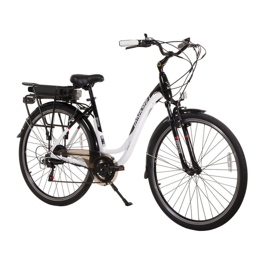
8802-46 CITYSCAPE 700c PEDAL-ASSIST BIKE
This manual contains important safety, performance and maintenance
information. Read the manual before taking your first ride on your new
bicycle, and keep the manual handy for future reference.
REGISTER your bike online at www.dynacraftbike.com
Advertisement
Table of Contents

Related Manuals for Dynacraft 700C DYNACRAFT CITY SCAPE PEDAL ASSIST BIKE 8802-46


Summary of Contents for Dynacraft 700C DYNACRAFT CITY SCAPE PEDAL ASSIST BIKE 8802-46
- Page 1 OWNER’S MANUAL 8802-46 CITYSCAPE 700c PEDAL-ASSIST BIKE This manual contains important safety, performance and maintenance information. Read the manual before taking your first ride on your new bicycle, and keep the manual handy for future reference. REGISTER your bike online at www.dynacraftbike.com...
- Page 2 IMPORTANT This quick start guide contains important information that should be reviewed before riding the pedal assist bicycle. This quick start guide does not replace the manual supplied with the bicycle. The manual contains important safety information, which should be read before riding the pedal assist bicycle. Always wear a helmet while riding your pedal assist bicycle! When using the pedal assist feature for the first time, ensure that you are in a safe open area to ride before you engage the pedal assist feature.
- Page 3 SPECIFICATIONS BIKE SIZE: 1850x620x1100mm TIRE SIZE : 700x38C BATTERY: 36V/9Ah, CONTROLLER: 24V250W FUSE: 30A CHARGER: 36V-2A MOTOR: 36V250W...
- Page 5 POWER BUTTON POWER LEVEL INDICATOR LIGHTS POWER LEVEL INDICATOR BUTTON POWER BUTTON The Power button controls the power supply to the battery only. The control module must be turned on or off separately. When the power is ON, the power level indicator will briefly show the current voltage of the battery. POWER LEVEL INDICATOR BUTTON When pressed, the four lights will indicate the current voltage of the battery.
-
Page 6: Charging Port
CHARGING PORT BATTERY LOCK/KEY... -
Page 7: Safety Precautions
SAFETY PRECAUTIONS Charge the battery pack for at least 10 hours before using your new pedal assist bike for the first time. To install the battery, slide the battery pack onto the bike rack steadily and then lock it into the rack with the supplied key. - Page 8 14. For long term storage, the battery should be charged at 60%-80% capacity ( about 3-4 hours). Repeat the same procedure every 3 months. 15. The battery pack should be charged promptly when the power is low (i.e. 1-2 LEDs on), to avoid damage caused by battery self-discharge.
- Page 9 POWER BUTTON WALK BUTTON POWER LEVEL INDICATOR MODE BUTTON PEDAL ASSIST SENSOR POWER BUTTON The Power button controls the power supply to the display only. The battery must be turned on or off separately. When the status is ON, the display will supply the current power and pedal assist levels. POWER LEVEL INDICATOR The four LED lights will indicate the current voltage of the battery.
-
Page 10: Using The Charger
HOW TO USE After powering on the battery and control module, set the pedal assist mode button to the first level. This will be indicated by the first light being illuminated on the pedal assist level indicator. Make sure you are in a safe open area to ride before you engage the pedal assist feature. - Page 11 Charging the Battery Initial charge time: 10 hours, and never charge the battery longer than 30 hours. Recharge time: up to 12 hours, and never charge the battery longer than 30 hours. When the pedal assist bicycle is not in regular use, recharge the battery at least once a month until normal use is resumed. 1.
- Page 12 Always ensure that you are in a safe open area to ride before you engage the pedal assist feature. Never engage the pedal assist feature unless you are in a balanced, ready to ride position with both hands on the handlebar controls.
- Page 13 Charger The charger supplied with the pedal assist bicycle should be regularly examined for damage to the cord, plug, enclo- sure and other parts. And in the event of such damage, the pedal assist bicycle must not be charged until the charger has been repaired or replaced.
-
Page 14: Quick Assembly Guide
QUICK ASSEMBLY GUIDE TOOLS REQUIRED 1. Allen key wrenches: 3 mm, 4 mm, 5mm, 6 mm 2. Open end wrench 8 mm-10 mm 3. Open end wrench 13 mm-15 mm 4. Standard Phillips head and Standard flat head screwdriver GETTING STARTED Open the carton from the top and remove the bike. -
Page 15: Front Wheel Assembly
FRONT WHEEL ASSEMBLY 1. Remove the plastic protective sleeve from the fork dropouts. 2. Make sure the brakes are fully opened. 3. Place wheel into fork drop outs. 4. Install retaining washers with raised lip pointed towards the fork, and insert into the small hole of the fork blade. 5. - Page 16 HANDLEBARS ASSEMBLY A loose stem bolt can cause a loss of steering control and result in serious injury or death. The stem must be tight enough for the wedge nut to bite into the inner surface of the steer tube. NOTE: The handlebar stem is pre-assembled to the handlebar at the factory.
- Page 17 IMPORTANT NOTE: Test the security of the handlebar stem within the steer tube of the front fork by clamping the front wheel between your knees and trying to move the stem from side to side. The handlebar should not move independent from the front wheel when applying pressure.
-
Page 18: Seat Assembly
SEAT ASSEMBLY The seat post must be inserted so that the Minimum Insertion Mark cannot be seen. The quick release mechanism must be tightened securely to prevent a sudden shift of the seat when riding. Failure to do this may cause loss of bike control. -
Page 19: Pedals Assembly
PEDALS ASSEMBLY Check for the right (R, red) sticker and left (L, green) sticker on each pedal and crank arm. Match the appropriate pedal to each crank (right to right and left to left) for assembly. Start each pedal spindle by hand to avoid stripping the threads. -
Page 20: Front Fender Assembly
FRONT FENDER ASSEMBLY 1. Install the pre-assembled fender into the fork legs facing forward with the fender bracket positioned behind the fork. 2. Loosen the mounting bolt (together with the washer) from the fender bracket, and insert the front reflector and the mounting bolt into the bracket, and secure the mounting bolt as show below. -
Page 21: Front Brake Assembly
FRONT BRAKE ASSEMBLY Insert the brake cable into the brake arm as shown in the photo b e l o w. Once the cable is secured to the brake arms, squeeze the brake lever several times checking the position of the brake shoes at the rim. The brake shoes should be 1mm away from the rim when in a relaxed position. - Page 22 LIMITED WARRANTY Although your new Dynacraft pedal assist bicycle is built tough, it is designed for recreational use only, not commer- cial use or extreme riding. Subject to the following limitations, all pedal assist bicycles manufactured for Dynacraft are warranteed to the original purchaser to be free of defects in materials and workmanship for a period from the date of...
- Page 23 • used as a rental Dynacraft does not offer an extended warranty; if you have purchased an extended warranty, it must be honored by the store from which you purchased the pedal assist bicycle or the appropriate party. For your records, keep your original sales receipt with this manual.
- Page 25 Please visit dynacraftbike.com for more information, Or call Customer Service at 1-800-551-0032, 7am-4pm Pacific Time Please have the following information available when you call: Model Number: (example: 8XXX-XX) Production Date: (example: 2014.XX.XX) Serial Number: (example: XXXXXXXXXXX) 2015 Printed in China...
Need help?
Do you have a question about the 700C DYNACRAFT CITY SCAPE PEDAL ASSIST BIKE 8802-46 and is the answer not in the manual?
Questions and answers