Table of Contents
Advertisement
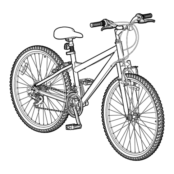
MOUNTAIN BIKE
THIS MANUAL CONTAINS IMPORTANT SAFETY, PERFORMANCE AND MAINTENANCE INFORMATION. READ THE MANUAL BEFORE TAKING YOUR FIRST
RIDE ON YOUR NEW BICYCLE, AND KEEP THE MANUAL HANDY OF FUTURE REFERENCE.
NOTE: Illustrations in this Manual are for reference purposes only and may not reflect the exact appearance of the actual product. Specifications are subject to change without notice.
OWNER'S
MANUAL
DO NOT return this item to the store.
Questions or comments?
1-800-551-0032
Advertisement
Table of Contents

Related Manuals for Dynacraft MOUNTAIN BIKE


Summary of Contents for Dynacraft MOUNTAIN BIKE
- Page 1 OWNER’S MANUAL MOUNTAIN BIKE THIS MANUAL CONTAINS IMPORTANT SAFETY, PERFORMANCE AND MAINTENANCE INFORMATION. READ THE MANUAL BEFORE TAKING YOUR FIRST RIDE ON YOUR NEW BICYCLE, AND KEEP THE MANUAL HANDY OF FUTURE REFERENCE. DO NOT return this item to the store.
- Page 2 Additionally, you can write or call us concerning missing parts or assembly questions. WARNING/IMPORTANT: Take notice of this symbol throughout this manual and pay particular attention to the instructions blocked off and preceded by this symbol. Dynacraft 1-800-551-0032 89 South Kelly Road, American Canyon, CA 94503 www.dynacraftbike.com...
- Page 3 HELMETS SAVE LIVES! WARNING: Always wear a properly fitted helmet when you ride your bicycle. Do not ride at night. Avoid riding in wet conditions. Correct fitting Incorrect fitting Make sure your helmet covers Forehead is exposed and vulnerable your forehead. to serious injury.
-
Page 4: About This Manual
Dynacraft shall not have any responsibility for any breakdown of the bicycle, its components or rider injuries that occur during such use. -
Page 5: Table Of Contents
CONTENTS A ABOUT YOUR BIKE ......7 Model/Serial Number Identification Customer Service Spaces to Write Info B BEFORE YOU RIDE . - Page 6 D BICYCLE ADJUSTMENTS ......33 Seat Adjustment Stem Adjustment Handlebar Adjustment Brake Adjustment Shifter Adjustment Derailleur Adjustment E MAINTENANCE AND INSPECTION .
-
Page 7: A About Your Bike
MODEL/SERIAL NUMBER IDENTIFICATION Each Dynacraft bicycle has a serial number stamped into the frame. The serial number can be found on the bottom of the crank housing as shown (see diagram below). The model number and production date are found on a sticker on the frame at the bottom of the seat tube. -
Page 9: Tool List
PARTS/TOOLS LISTS 1 Frame 17 Front Derailleur Tools Required 2 Brake Lever (L and R) 18 Crankset 3 Handlebar 19 Rear Derailleur 4 Grip (L and R) 20 Rear Cassette 5 Front Reflector 21 Pedal (L and R) 6 Stem 22 Seat Clamp 7 Head Tube 23 Rear Reflector... -
Page 10: Frame Sizing
FRAME SIZING When selecting a new bicycle, the correct choice of frame size is a very important safety consideration. To determine the correct size bicycle for the rider: • Straddle the assembled bicycle with feet shoulder width apart and flat on the ground •... -
Page 11: Rules Of The Road/Safety Tips
Most traffic regulations apply to bike riders as well as automobile operators. 9. ONE RIDER PER BIKE. NEVER CARRY OTHER RIDERS. This is dangerous and makes the bike harder to control. The bicycles distributed by Dynacraft BSC, Inc. are intended for one rider only. - Page 12 10. ALWAYS BE ALERT. BE ALERT – BE ALERT – pedestrians have the right of way. when riding near parked cars - ride far enough away from the cars so that you won’t get hit if someone opens the car door. 11.
-
Page 13: Night Riding
NIGHT RIDING Riding a bicycle at night is much more dangerous than riding during the day. A bicyclist is very difficult for motorists and pedestrians to see. Therefore, children should never ride at dawn, dusk or at night. Adults who choose to accept the greatly increased risk of riding at dawn, dusk or at night need to take extra care both riding and choosing specialized equipment which helps reduce that risk. -
Page 14: Safety Checklist
SAFETY CHECKLIST Before every ride, it is important to carry out the following safety checks: (For information and instructions on performing specific equipment checks, locate the relevant section in the manual referenced on pages 5–6.) 1. BRAKES • Ensure front and rear brakes work properly. •... - Page 15 5. WHEELS AND TIRES • Ensure tires are inflated to within the recommended range as displayed on the tire sidewall. • Ensure tires have tread and have no bulges or excessive wear. • Ensure rims run true and have no obvious wobbles or kinks. •...
-
Page 16: C Bicycle Assembly
9. If any parts are missing or damaged, or if you have any trouble with the assembly, don’t return the item to the store. Call Dynacraft directly at 1-800-551-0032 or visit our website at www.dynacraftbike.com, find your bike, and locate the assembly video in the Information Center. -
Page 17: Pedals
1. PEDALS WARNING: Attachment of an incorrect pedal into a crank arm will cause irreparable damage. Unless the shoulder of the pedal spindle is tight to the face of the crank arm, the pedal may back out causing serious injury or death. Make it tight so the shoulder is in complete contact with the surface of the crank arm. -
Page 18: Seat
2. SEAT WARNING: The seatpost must be inserted far enough so that the minimum insertion marks cannot be seen. Add some white grease to the inside of the seat tube, and slide the seatpost Figure 6 into the bicycle. Make sure that the minimum insertion mark is completely Seatpost covered and that the seat is pointing forward in alignment with the bicycle (see Figures 6 and 7). -
Page 19: Testing Seat Clamp And Post Clamp Tightness
If your bike has a quick release lever (see Figure 9), tighten it by holding the lever in the “open” position and tightening the nut on the opposite side by hand. Slowly close the quick release lever, and you should notice resistance Closed when the lever is half way shut. -
Page 20: Handlebar/Stem
4. HANDLEBAR/STEM Minimum insertion WARNING: To prevent steering system damage and possible loss of control, the mark stem must be inserted enough so that the minimum insertion marks are completely covered (see Figure 14). Figure 14 Add some white grease to the inside of the fork steerer tube. Before installing the stem, ensure that you have all the parts present and installed in the correct order Fork Cone (see Figure 17). - Page 21 Pre-Load Bolt Top Cap The stem should be pointing towards the front of the bike, aligned with the front tire (see Figure 18). Depending on the type of bolt, tighten the stem bolt with either (B) an adjustable wrench or (C) a 4, 5, or 6 mm Stem Figure 18 Allen wrench (see Figure 19).
- Page 22 The handlebars should come attached to the stem. Simply ensure that the brake and derailleur cables track smoothly, and that the handlebar bolt(s) are properly tightened with (C) a 4, 5, or 6 mm Allen Wrench. (See Figures 23-25). In the case of a 2 or 4-bolt stem, tighten the bolts alternating between bolts every few turns.
-
Page 23: Testing Handlebar And Stem Tightness
5. TESTING HANDLEBAR AND STEM TIGHTNESS To test the tightness of the stem, straddle the front wheel between your legs tightly (see Figures 26 & 27). Try to turn the handlebar back and forth. The handlebar should not slip or move independently of the front wheel at all. If the handlebar does move, re-align the stem with the front wheel and tighten the stem bolt. -
Page 24: Front Wheel
6. FRONT WHEEL Before installing the front wheel, ensure that the brakes are opened enough to allow the tire to fit through them. On side-pull equipped bikes, you may have to loosen the cable anchor bolt (see Figure 31) in order to allow the tire to fit through. On Linear Brake equipped bikes, squeeze the brake arms together by hand, and lift the cable out of the carrier to open up the brakes (see Figure 33). -
Page 25: Brakes
7. BRAKES Cable WARNING: Anchor Bolt When assembling or adjusting the brakes, make sure the cable anchor nut is tight. Failure to securely tighten the nut could result in brake failure and Brake arm personal injury (see Figure 31). Brake pad 7A. - Page 26 7C. Disc Brakes When installed properly, the disc brake rotor should be centered between the brake pads, and securely fastened to the wheel (see Figure 34). Use (C) a 4, 5, or 6 mm Allen Wrench to check the rotor mounting bolts to ensure that none of the bolts are loose.
-
Page 27: Testing Brake Functions
8. TESTING BRAKE FUNCTIONS As part of the initial assembly, you will need to check test the brake function and adjust the brakes as necessary to make sure they are functioning properly. For detailed instructions on brake adjustments, please see pages 35–37. Front brake Rear brake To test the function of the front hand brake, lift the front of... -
Page 28: Dual Suspension
9. DUAL SUSPENSION Front Rear Fork Dual suspension bikes are equipped with a front fork as well as a rear Suspension suspension generally located below the seat (see Figure 38). The rear suspension unit is a combination of a piston that works in conjunction with a spring to allow the rear swing arm to rotate on a pivot point. -
Page 30: Tire Inflation
10. TIRE INFLATION WARNING: Tires must be properly inflated before riding. Never exceed the maximum pressure (PSI) that is listed on Figure 42 the side of the tire. Incorrectly seated Properly seated WARNING: Be sure to check that the edge (beads) of both tires are evenly seated the entire way around on both sides of the tire. -
Page 31: Reflectors
11. REFLECTORS Reflectors are pre-installed on your bicycle Front reflector on the pedals, wheels, seatpost, and Rear reflector handlebars (see Figure 46). Ensure that the handlebar reflector is pointing straight forward and perpendicular to ground, and position the rear reflector so that it points straight backwards. - Page 32 12. ACCESSORIES Your bike may come with some or all of these accessories that require attachment and/or assembly. 12A. Kick Stands If the kickstand is not mounted to your bicycle, place the bicycle in an upright position against a wall or have someone hold it upright. Place the kickstand in the bracket mounted on the frame and use a pair of (E) Standard Slip Joint Pliers to secure the fixing bolt to keep the kickstand in place.
-
Page 33: D Bicycle Adjustments
BICYCLE ADJUSTMENTS SEAT ADJUSTMENT You can adjust the up and down tilt of your seat as well as the forward and back position by loosening the seatpost Closed Open hardware at the bottom of your seat. (See Figure 51.) Be careful not to loosen them all the way so that the nut comes off on either side. -
Page 34: Stem Adjustment
STEM ADJUSTMENT To raise or lower your stem, use an adjustable wrench or Allen wrench on the stem bolt to loosen the stem (see Figure 56). Do not remove this bolt completely, as the stem wedge may fall inside your frame. Make sure the stem is inserted enough so that the minimum Minimum insertion marks on your stem are completely covered... -
Page 35: Handlebar Adjustment
HANDLEBAR ADJUSTMENT To adjust the handlebars forward and backwards, loosen the stem bolt or bolts. Your bike may have one (see Figure 59), two (see Figure 60), or four (see Figure 61) bolts holding the handlebar in place. Do not completely remove these bolts, simply loosen them until you are able to move the handlebar to the desired position. -
Page 36: Brake Adjustment
BRAKE ADJUSTMENT WARNING: Always make sure your brakes are properly adjusted before riding (see Page 27, Testing Brake Functions). Brake Pads • Ensure that the wheel is properly centered within the dropouts and is not out of true (see Figure 63). •... - Page 37 Cable Brake Cable Carrier Linear Pull Brakes • Once the brake pads are properly positioned, loosen the cable anchor nut on the Cable Anchor Nut Brake Arm (See Figure 65). Firmly squeeze the brake pads against the rim of the tire, pull the cable taut, and re tighten the cable anchor nut using either (C) a 4, 5, Brake arm or 6 mm Allen Wrench or a pair of (E) Standard Slip Joint Pliers.)
-
Page 38: Shifter Adjustment
SHIFTER ADJUSTMENT WARNING: Do not ride a bicycle that is not shifting properly. Overlooking proper adjustments may cause irreparable damage to the bicycle and/or bodily injury. Never move the shifter while pedaling backward, nor pedal backwards after having moved the shifter. This could jam the chain and cause serious damage to the bicycle and/or rider. -
Page 39: Derailleur Adjustment
DERAILLEUR ADJUSTMENT With the chain in the middle cog on the crankset (#2 on the left shifter), lift the rear wheel off the ground and pedal slowly. While continuing to pedal, shift the right (rear) shifter through the rings. It should shift smoothly, and stay in gear without jumping between gears or excessive noise. -
Page 40: E Maintenance And Inspection
MAINTENANCE AND INSPECTION WARNING: Inspect the bicycle frequently. Failure to inspect the bicycle and to make repairs or adjustments, as necessary, can result in injury to the rider or to others. Make sure all parts are correctly assembled and adjusted as written in this manual. •... -
Page 41: Tire Removal/Seating
WARNING: Do not attempt chain repairs. If there is a problem with the chain, have a bicycle service shop make any repairs. The chain must be at the correct tightness. If too tight, the bicycle will be difficult to pedal. If too loose, the chain can come off the sprockets. -
Page 42: Lubrication
LUBRICATION Frequency Component Lubricant How to Lubricate Weekly Chain Chain lube or light oil Brush on or squirt Derailleur Wheels Chain lube or light oil Oil can Derailleurs 3 drops from oil can Brake Calipers 2 drops from oil can Every Six Months Freewheel 2 squirts from oil can... -
Page 43: Bearing Inspection
BEARING INSPECTION • Maintenance Frequently check the bearings of the bicycle. Have a bicycle shop clean and re-grease the bearings once a year or any time they do not pass the following tests: • Header Bearings The fork should turn freely and smoothly at all times. With the front wheel off the ground, you should not be able to move the fork up, down, or side-to-side in the head tube. -
Page 44: Limited Warranty
LIMITED WARRANTY use on streets, roads and bicycle-approved trails and are for non- Although your new Dynacraft bicycle is built tough, it is designed for competition riding that is safe and within the rider’s experience and recreational use only, not commercial use or extreme riding Subject limits. - Page 46 Dynacraft Customer Service 1-800-551-0032 7AM to 4PM Pacific Standard Time DO NOT return this item to the store. STOP Please call Dynacraft for assistance. Please have the following information available when you call: Model Number: (sample: 8802-33) Production Date: (sample: 03.03.2015)
Need help?
Do you have a question about the MOUNTAIN BIKE and is the answer not in the manual?
Questions and answers
Can you remove and replace a handlebar, not the stem, that has a single bolt?