
Subscribe to Our Youtube Channel
Related Manuals for Adam Equipment MDW – 300L


Summary of Contents for Adam Equipment MDW – 300L
- Page 1 Adam Equipment MDW – 300L HEALTH AND FITNESS SCALE with BMI ADAM EQUIPMENT CO. LTD. p.n. 700660159 Rev. A2, Apr 2014 Page 1...
-
Page 2: Table Of Contents
CONTENTS INTRODUCTION ................... 3 TECHNICAL SPECIFICATIONS ..............3 DISPLAY AND KEY DESCRIPTIONS ............4 SETTING UP THE SCALE ................5 FUNCTION ....................7 WEIGHING ....................7 MEASURING HEIGHT ................8 MEASURING BODY MASS INDEX (BMI) ..........8 CALIBRATION ....................9 USER PARAMETERS ................ -
Page 3: Introduction
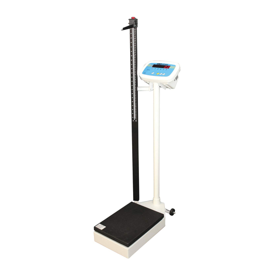
1.0 INTRODUCTION • The MDW 300L scale is a Digital Health and Fitness Scale with Body Mass Index (BMI) readout. • It is an accurate electronic device with advanced design and stable performance. • It is designed to measure both the weight and the height of a person and compute the BMI index. -
Page 4: Display And Key Descriptions
3.0 DISPLAY AND KEY DESCRIPTIONS KEYS FUNCTIONS [On/Off / To turn the scale on or off. Zero] To zero the scale if the display drifts from zero. [Tare] ↵ ↵ ↵ ↵ To tare the scale, if necessary. Accept settings as required [Units / To toggle the weighing unit between Kg and Lb. -
Page 5: Setting Up The Scale
4.0 SETTING UP THE SCALE • Take the scale out of the box. 1. Locate the 4 screws (2) 2. Place the cable (4) through the pillar (3). 3. Insert the 4 screws (2) through the holes on the pillar bracket and secure the bracket to the indicator (1), 4. - Page 6 9. Place the indicator cable (4) and the load cell cable (13) together near the hole on the base (16). 10. Plug the two connectors (15) together. 11. Position the connector inside the base (16). 12. The cables should be fixed to the base using the clip provided (14).
-
Page 7: Function
5.0 FUNCTION WEIGHING • Place the Scale on an even floor and press the [On/Off] key. • The instrument performs a self-test after which it is ready for operation. • Press the [On/Off] key and the machine switches off. • The person to be weighed can step on to the platform once the scale shows 0.0 on the display. -
Page 8: Measuring Height
MEASURING HEIGHT • To measure someones height, it is necessary to extract the measuring rod and place the height arm on top of the head of the person being measured. • For shorter heights the height arm can be released by pressing the red button on the top of the height rod, and then moving the height arm to the lower section of the height pillar. -
Page 9: Calibration
6.0 CALIBRATION Before calibrating the scale, you should ensure that you have a suitable known weight for calibration. 1. When in normal weighing mode with the scale at zero press and hold down [TARE] and [ON / OFF] keys to enter the calibration mode. 2. -
Page 10: User Parameters
7.0 USER PARAMETERS This indicator has 4 parameter settings that can be selected. When the scale is in normal weighing mode, press and hold down the [ON / OFF] key and the [UNIT] key for 3 seconds until ‘Setup’ is shown on the display. When in the SETUP mode, press the [Print/Hold] key to change the flashing digits, and [TARE] key to confirm the flashing digits and move to the next parameter setting. -
Page 11: Rs232 Communications
8.0 RS232 COMMUNICATIONS The Interface parameters are: Connection details are: RS-232 output of weighing data Connector: 9 pin d-subminiature socket ASCII code Pin 2 Output 9600 Baud rate (fixed) Pin 3 Input 1 start bit, 8 data bits,1 stop bit Pin 5 Signal Ground No Parity... - Page 12 8.3 When Parameter S.F. in section 7 is set to 1 : Continuous output of the current displayed reading and unit, and no data is received. The output format is as below: <LF>< reading, minus, decimal point, weight unit>GR<CR><EXT> Or <LF>< reading, minus, decimal point, weight unit>NT<CR><EXT> 8.4 When Parameter S.F.
- Page 13 U1U2: measure units, kg, lb 8.5.3 Commands and response (1) Command: W<CR> (57h 0dh) Response: ①<LF>^^^^^^u1u2<CR><LF>H1H2H3<CR><ETX>---over capacity ①<LF>______u1u2<CR><LF> H1H2H3 <CR><ETX>---under capacity ①<LF>---------u1u2<CR><LF> H1H2H3<CR><ETX>---zero-point error ① < L F > < p > w 1 w 2 w 3 w 4 w 5 w 6 < d p > w 7 u 1 u 2 < C R > < L F > H 1 H 2 H 3 < C R > <ETX>...
- Page 14 Table1: The status bits definition: Byte 1 (H Byte 2 (H Byte 3 (H 0= not under 01=normal work 0=stable capacity mode 1= not stable 1= under capacity 10= hold work 0= not at zero 0= not over mode 00=not define point capacity 11= not define...
-
Page 15: Error Messages
9.0 ERROR MESSAGES 0¯ ¯ ¯ ¯ ¯ Zero point is over the setting range 0_ _ _ _ _ Zero is below the setting range Ad¯ ¯ ¯¯ ADC is over max. range; Ad _ _ _ _ ADC is below min. range; There is an error in the EEPROM EEP.Er There is an error in calibration... - Page 16 Page 16...
-
Page 17: Warranty Information
WARRANTY INFORMATION Adam Equipment offers Limited Warranty (Parts and Labour) for the components which fail due to defects in materials or workmanship. Warranty starts from the date of delivery. During the warranty period, should any repairs be necessary, the purchaser must inform their supplier, or Adam Equipment Company. - Page 18 Page © Adam Equipment Company 2014...
-
Page 19: Fcc Compliance
Shielded interconnect cables must be employed with this equipment to insure compliance with the pertinent RF emission limits governing this device. Changes or modifications not expressly approved by Adam Equipment could void the user's authority to operate the equipment. WEEE COMPLIANCE... - Page 20 For a complete listing of all Adam products visit our website at www.adamequipment.com © Copyright by Adam Equipment Co. Ltd. All rights reserved. No part of this publication may be reprinted or translated in any form or by any means without the prior permission of Adam Equipment.
Need help?
Do you have a question about the MDW – 300L and is the answer not in the manual?
Questions and answers