
Subscribe to Our Youtube Channel
Related Manuals for Danfoss ECtemp 550


Summary of Contents for Danfoss ECtemp 550
- Page 1 MAKING MODERN LIVING POSSIBLE Installation Guide ECtemp 550 Electronic Intelligent Thermostat www.EH.danfoss.com...
- Page 2 Danfoss A/S is not liable or bound by warranty if these instructions are not adhered to during installation or service. The English language is used for the original instructions. Other languages are a translation of the original instructions. (Directive 2006/42/EC)
-
Page 3: Table Of Contents
Disposal Instruction ..Introduction The ECtemp 550 thermostat controls electrical floor heat- ing elements using a built-in and/or an external tempera- ture sensor. The thermostat can be optimised for the room within a few days after the installation by continuously col- lecting updated temperature data. -
Page 4: Technical Specifications
ECtemp 550 Note: This thermostat does not apply to tariff control or similar systems. More information on this product can also be found at: ectemp.danfoss.com Technical Specifications Operation voltage 220-240 V~, 50/60 Hz Standby power consump- <500mW tion Relay: Resistive load Max. - Page 5 ECtemp 550 Temperature range +5 to +35°C (room) or +5 to +50 (floor) Lowering in economy peri- 0 to -30°C Offset (temp. correction) -5,5 to +5,5°C Cable specification max. 1x4mm or 2x2,5mm Ball pressure temperature 75°C Pollution degree Degree 2 (domestic use)
-
Page 6: Safety Instructions
ECtemp 550 Safety Instructions Make sure the mains supply to the thermostat is turned off before installation. If the thermostat is installed in a net- work, the mains supply to all thermostats in the network must be off. IMPORTANT: When the thermostat is used to control a... -
Page 7: Mounting Instructions
ECtemp 550 Mounting Instructions Please observe the following placement guidelines: Place the thermostat at a suitable height on the wall (typically 80-170cm.). The thermostat should not be placed in wet rooms. Place it in an adjacent room. Always place the thermostat according to local regulation on IP classes. - Page 8 ECtemp 550 Do not place the thermostat in a way that it will be exposed to direct sunlight. Note: A floor sensor enables a more accu- rate temperature control and is recom- mended in all floor heating applications and mandatory under wooden floors to reduce the risk of over-heating the floor.
- Page 9 ECtemp 550 Follow the steps below to mount the thermostat: 1. Open the thermostat: ▪ Push down the release tab. ▪ Carefully detach the front cover. ▪ Remove the two screws. ▪ Carefully detach the display module. Make sure to pull it straight out to avoid damaging the 8-pin con- nector plug on the back of the module.
- Page 10 ECtemp 550 2. Connect the thermostat according to the connection diagram. IP30 0T30 D550 Sensor Max.Load Mains 16 (1) A 220-240V~ devinet LOAD LOAD The screen of the heating cable must be connected to the earth conductor of the power supply cable by us- ing a separate connector.
- Page 11 ECtemp 550 3. Mount and reassemble the thermostat. = Screw holes for mount and reassemble the ther- mostat. ▪ Fasten the thermostat to a socket or an exterior wall box by driving the screws through the holes in each side of the thermostat.
-
Page 12: Settings
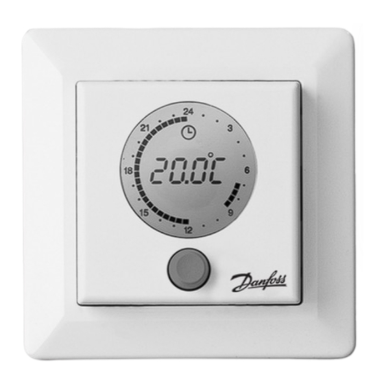
ECtemp 550 Settings The thermostat is automatically activated when the power supply is turned on. Note: If the unit has never been activated before, basic con- figuration settings must be specified. 1. Symbol for frost protection. 2. Numeric display of time, temperature, text, etc. -
Page 13: Time And Day Of Week Settings
ECtemp 550 Time and Day of Week Settings 1. Press and hold the button for 3 seconds. The clock symbol appears on the display and the day of the week is shown as a number (from 1-7) just below the time. -
Page 14: Basic Settings
ECtemp 550 Basic Settings The following table shows the default values of the basic settings: Item Default setting Options Network type Alone (ALO) Independent (ALO) Master (MAS) Slave (SLA) Adaptive function On (AdAP) On (AdAP) Off (OFF) Sensor Room + floor sen-... - Page 15 ECtemp 550 How to enter the basic configuration settings 1. Press and hold the button for 12 seconds until “COdE” appears. 2. Turn the button clockwise until “0044” appears. 3. Press the button once to confirm. Network: How to specify whether you want to connect...
- Page 16 ECtemp 550 To define this unit as a slave unit in the network, choose SLA. Only one unit in the network can be defined as master unit. All slave units will respond to and send informa- tion to the master unit. Time, day of week and econo- my periods will be controlled from the master unit.
- Page 17 ECtemp 550 Adaptive regulation: How to specify whether or not to optimise this thermostat for the room by timing heat- ing start/stop 1. Turn the adaptive function on or off. To let the unit continuously collect updated room data, choose AdAP.
- Page 18 ECtemp 550 Sensor: How to specify whether an external floor sen- sor, the built-in room sensor or both is used to control the floor heating 1. Turn the button to choose one of the following sensor settings: If both a room sensor and a floor sensor is used, choose rFS.
- Page 19 ECtemp 550 How to set the maximum floor temperature Special condition: This setting only applies if a floor sen- sor is used (the FS or rFS sensor option has been set). 1. Turn the button to change the tempera- ture.
- Page 20 ECtemp 550 Thermal Examples of floor- Details Approximate resist- setting for ance 25˚C floor [m2K/W] temperature 0.05 8 mm HDF based 28˚C > 800 kg/m laminate 0.10 14 mm beech par- 650 - 800 31˚C quet kg/m 0.13 22 mm solid oak 32˚C...
-
Page 21: Warranty
ECtemp 550 Temperature decrease: How to specify how much the temperature is to be lowered during economy periods Note: If normal room heating is installed, we recommend lowering the temperature by no more than approx 5 °C. By default, the temperature decrease is set to -5 °C 1. - Page 22 ECtemp 550 Installation Guide...
- Page 23 Danfoss can accept no responsibility for possible errors in catalogues, brochures and other printed material. Danfoss reserves the right to alter its products without notice. This also applies to products already on order provided that such alterations can be made without subsequential changes being necessary in specifications already agreed.
Need help?
Do you have a question about the ECtemp 550 and is the answer not in the manual?
Questions and answers