Table of Contents
Advertisement
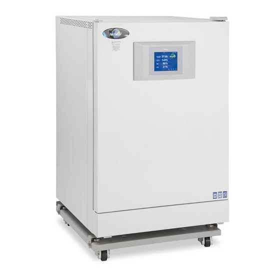
Air-Jacketed DH Invitrocell CO
Incubator
2
Models
NU-5800 (Series 1)
NU-5800E (Series 1)
Operation and Maintenance Manual
March 2013
Revision 3
Manufactured By:
NuAire, Inc.
2100 Fernbrook Lane
Plymouth, MN 55447
Toll-Free: 1-800-328-3352
In Minnesota: (763)-553-1270
Fax: (763)-553-0459
OM0211
Page 1 of 48
Advertisement
Table of Contents
Troubleshooting

Subscribe to Our Youtube Channel
Related Manuals for NuAire NU-5800


Summary of Contents for NuAire NU-5800
- Page 1 Air-Jacketed DH Invitrocell CO Incubator Models NU-5800 (Series 1) NU-5800E (Series 1) Operation and Maintenance Manual March 2013 Revision 3 Manufactured By: NuAire, Inc. 2100 Fernbrook Lane Plymouth, MN 55447 Toll-Free: 1-800-328-3352 In Minnesota: (763)-553-1270 Fax: (763)-553-0459 OM0211 Page 1 of 48...
- Page 2 BCD-15634 ............ Sensor Bay Assembly BCD-15178 ............ NU-5510/E Tubing Configuration BCD-15191 ............ Display / Outer Door Assembly ELECTRICAL SCHEMATICS BCD-15670 ............ Electrical Schematic, NU-5800/E BCD-15190 ............ Main Control Board Electrical Schematic OM0211 Page 2 of 48 Rev 3 March 2013...
- Page 3 Sterility Reliability Like all NuAire equipment, this Incubator has been designed to provide the highest quality standards of performance with matching computer technology, precise temperature control, and CO gas control system combining state-of-the-art technology with years of design, quality, and manufacturing experience.
- Page 4 Keep these operating instructions close to the unit so that safety instructions and important information are always accessible. • Should you encounter problems that are not detailed adequately in the operating instructions, please contact your NuAire Representative of NuAire technical Services. OM0211 Page 4 of 48 Rev 3 March 2013...
- Page 5 1.9 Explanation of symbols Symbol Description Safety alert symbol indicates a potentially hazardous situation which, if not avoided, could result in death WARNING of serious injury. Safety alert symbol indicates a potentially hazardous situation which, if not avoided, may result in minor or CAUTION moderate injury.
- Page 6 Flammable Hazard Lead Free CAUTION used without the safety alert symbol CAUTION indicates a potentially hazardous situation which, if not avoided, may result in property damage. Hot Surface Burn Potential OM0211 Page 6 of 48 Rev 3 March 2013...
- Page 7 2.0 Performance Parameters and Features • Both the interior and exterior of the DH are constructed of 18 to 16-gauge steel. The interior is highly polished type 304 L 16 gage stainless steel, using crevice-free construction. All exposed edges are deburred to insure no sharp edges. The exterior is cold rolled 16 &...
- Page 8 3.0 Models & Features 3.1 Dimensions (see also Specification Drawing BCD-14784) Overall Dimensions - inches (mm): Model NU-5800/E Height: Exterior: 39.688 in (1008 mm) Width: 26.500 in (673 mm) Depth: 27.188 in (691 mm) Foot print: 23.5 in (597 mm) wide x 20.75 in (527 mm) deep Height: Interior: 28.500 in (723.900mm)
- Page 9 3.3 Standard Items Packed With Unit • Four (4) stainless steel shelves • Eight (8) stainless steel shelf brackets • One (1) water pan • Gas tube • Access port plug with breather hole • One (1), 2 meter (6.5 ft.) electrical cord •...
- Page 10 OM0211 Page 10 of 48 Rev 3 March 2013...
- Page 11 4.0 Test Performance & Procedures All equipment is thoroughly inspected at the NuAire Factory at the time of shipment. Quality control is maintained by constant surveillance over the product, beginning at the receipt of purchased material and concluding with a final inspection, which certifies the Incubator performance to the specifications.
- Page 12 5.0 Warranty NuAire, Inc. warrants that it will repair F.O.B. its factory or furnish without charge F.O.B. its factory a similar part to replace any material in its equipment within 24 months after the date of sale if proven to the satisfaction of the company to have been defective at the time it was sold provided that all parts claimed defective shall be returned, properly identified to the company at its factory, charges prepaid.
- Page 13 7.3 Shelf & Water Pan Installation Before installation of the shelves, and water pan, NuAire recommends to decontaminate all surfaces within the interior chamber, glass door, and outer door with gasket. They can be wiped down with a disinfectant of 70 percent alcohol or similar non-corrosive antimicrobial agent.
- Page 14 OM0211 Page 14 of 48 Rev 3 March 2013...
- Page 15 7.4 Electrical The electrical supply circuit to the Incubator must conform to all national and local electrical codes. Consult the serial-data plate, located at the front of the right side of the Incubator, for voltage, cycle, phase, and ampere requirements before making connection. Plug the power cord securely into a grounded power source. VOLTAGE SHOULD NOT VARY MORE THAN 5% FROM SERIAL PLATE RATINGS.
- Page 16 0 to 2 BAR (100 PSI or 6 BARS maximum). This gauge will indicate the actual CO pressure to the Incubator. Some single stage CO pressure regulators have two gauges. USE A TWO-STAGE REGULATOR. All NuAire Incubators use in such small quantities that precise metering of CO input pressure is important for maximum performance.
- Page 17 7.7 Water Pan Place water pan in the center on the bottom of the chamber and fill with Single distilled water no purer than 1 Mega Ohm. It is recommended to fill the pan to about 1/2 inch below the top rim. See Sections 3.1 and 8.2 for more specifications and operational details.
- Page 18 8.0 DH Operation The Incubator is designed to provide a sterile, constant temperature, constant CO level and naturally humidified atmosphere for optimum growth of tissue cell cultures and other organisms requiring this precise environment. To operate the Incubator properly, the following parameters must be reviewed, carefully set, and/or prepared. 8.1 Sterility The chamber environment is not selective.
- Page 19 8.3 Control System Introduction The NuAire Incubator Control Electronics system is designed to serve the control requirements of the Incubator chamber. Temperature and CO levels are controlled by preset values to provide the optimum conditions for culture growth within a chamber.
- Page 20 NU-Touch LCD menu system is accomplished through the following methods: • Touching a “graphic” Icon like the NuAire Logo in the Main Screen which access the System Settings menu, or lead you to an Enter Password screen when a password has been established.
- Page 21 8.3.5 Functioning accessed from the System Settings screen: The “System Settings” menu screen can be accessed from the “Main Screen” by touching the NUAIRE logo: Environmental Set-Points: Allows adjustment of Temperature, CO2, Door, and Perimeter heater power level settings. Note: You can also access the Environmental set points by touching any control system numerical value in the MAIN SCREEN.
- Page 22 8.3.9 Diagnostic and calibration assists. To access the Service Settings Menu, perform the following steps: NuAire Logo → Service Settings → 9876 Enter. You are now in the Service Settings Menu (screen). This screen provides you the capability to review and analyze numerous Incubator functions including the following: •...
- Page 23 The “Alarm Status” button indicates is triggered when a timer for a maintenance reminder runs to zero. This text appears in red just below the NuAire Logo (paragraph 8.4.2 and 8.4.3). The “Alarm Status” button and audible alarm indicates the abnormality. A catastrophic temperature control condition will de-energize the safety relay and cause the chamber to cool below the set point.
- Page 24 OM0211 Page 24 of 48 Rev 3 March 2013...
- Page 25 8.6 Front Component Panel The front component panel contains the following functions. See BCD-15180 8.6.1 CO2 Supply Filter The CO2 supply filter is installed at the factory and should be changed following the instructions found in Maintenance Section 10. 8.6.2 Air Inlet Filter - All models The Incubator is provided with clear vinyl tubing and a 0.3-micron HEPA filter.
- Page 26 OM0211 Page 26 of 48 Rev 3 March 2013...
- Page 27 8.8 Standby Mode Operator Interactions The NuAire incubator automatically enters the standby mode when necessary. There is no action required by the user to enter this mode. All functions that put the incubator in standby mode automatically start a 10 minute timer. If the function is not interfaced through the screen on the NU-Touch display the incubator the returns to the MAIN SCREEN and switches to RUN mode.
- Page 28 The diagnostic mode allows the operator to configure and/or check the Incubator for input/output signals manually and individually. To initiate the diagnostic mode, perform the following from the ‘Main’ screen: • Select the NuAire Logo to enter “System Settings” • Select “Service Settings” and enter 9876, and then hit enter (ENT) •...
- Page 29 Temperature Control Diagnostics 1. Safety Relay This function shows the current state of the safety relay. LCD display will show “On” or “Off” corresponding to the relay condition. On for closed or set or yes. 2. Chamber Temperature Sensor This function shows on LCD the current values, calibrated (displayed) and not calibrated of the temperature sensor controlling the chamber temperature.
- Page 30 Format: Option (Default, Min/Max) All the options for the NU-5800 Incubator use this same format. The default is set at the factory and can be restored in the field with a Master or a Factory reset command. On the following pages, there is a short description of each Option with its Default/Min/Max setting, followed by a more detailed description.
- Page 31 To perform a Factory Reset, you will need to do the following: NuAire Logo → Service Settings → 9876 Enter → Reset → Factory Reset → Confirm The Incubator will perform the Factory Reset and return to the Main screen.
- Page 32 Touch the “Model Number” text then follow the screen prompts as shown below. Pressing continue on the choose Region screen will bring you back to the Factory Set-Up screen showing the Model Number you just entered. Default is NU-5800 if no model number is entered ...
- Page 33 9.0 Calibration Proper calibration of the incubator involves four parameters: chamber temperature, door temperature, perimeter temperature, and CO sensor. The first three, chamber, door, and perimeter temperature should be completed and stabilized before any CO sensor calibration is performed. Below, each calibration procedure is described in detail. For the best results, follow the procedure carefully, and if the desired result is not achieved, try procedure again from the start.
- Page 34 9.2 Door and Perimeter Duty Cycle adjustments for Temperature Calibration The Door and Perimeter heaters are run on “Base Duty Cycle” calculations that is automatically increased or decreased to run in accordance with the chamber temperature at a chosen set point. These duty cycles work in the controlled lab environment but due to the many variables involved in temperature control there is also a manual adjustment.
- Page 35 9.3 Setting Air Injections If there is still some undesired condensation in the chamber when the door and perimeter heaters are set for the desired result, the air injections can be adjusted. There is a control for length of the air injection labeled, Air Inject Time, and the frequency that air is injected called, Air Inject Cycle.
- Page 36 9.4.4 Closed Door CO Sensor Calibration Routine • Attach independent CO2 monitoring device to the sample port on the front of the unit • Enter CO2 calibrations by means of Service Settings • Select the “CO2 Closed Door Zero Span” text •...
- Page 37 10.1 Chemical Decontamination of the Incubator Chamber To chemically decontaminate NuAire Incubator inner chambers, users may use the traditional formaldehyde or Chlorine Dioxide in gas form, or Vapor Phased Hydrogen Peroxide. All three of the chemicals are compatible to all parts within NuAire Incubator chambers.
- Page 38 Responding to the notification: From the main screen press the NuAire Logo / Service settings / General Option / Settings / Filter Maintenance to access the Filter Maintenance Adjustments screen. In this screen you can extend the alarm by 1 month by pushing the Extend? button.
- Page 39 11.0 Error Indicators & Troubleshooting Step 1 NOTE ALL ERROR INDICATORS. When the Incubator is running, the Alarm Status button indicates an error. Pressing the Alarm Status button, entering the correlating Alarms Menu and pressing the Silence button in the Alarms Menu will silence the audible alarm until Diagnostics is entered or another alarm becomes active.
- Page 40 Temp Under Set Point, Faulty TRIAC, replace control board during normal running and in Faulty chamber heater contact NuAire Technical Service. Door/Perimeter heater needs to be increased with a high temperature set-point in a low ambient temperature -Sensor temperature (differential) Check temperature sensor calibration error normal running.
- Page 41 12.1 Remote Alarm Contacts The NuAire DH Incubator contains a set of contact points to connect to a remote alarm system. The contacts are located on the rear panel (see page 14). The contacts are housed in a modular (RJ-11) telephone jack and rated for (30V at 1 Amp).
- Page 42 13.0 Electrical/Environmental Requirements 13.1 Electrical (Supply voltage fluctuations not to exceed +/- 10%) NU-5800 115V, 50/60Hz, 1 Phase, 6.0 Amps NU-5800E 230V, 50/60Hz, 1 Phase, 3.0 Amps Start Up Power 345 WATTS Running Power 175 WATTS 13.2 Operational Performance (for indoor use only) Environment Temperature Range: 60°F-85°F (15.5°C –...
- Page 43 OM0211 Page 43 of 48 Rev 3 March 2013...
- Page 44 OM0211 Page 44 of 48 Rev 3 March 2013...
- Page 45 OM0211 Page 45 of 48 Rev 3 March 2013...
- Page 46 OM0211 Page 46 of 48 Rev 3 March 2013...
- Page 47 OM0211 Page 47 of 48 Rev 3 March 2013...
- Page 48 OM0211 Page 48 of 48 Rev 3 March 2013...
Need help?
Do you have a question about the NU-5800 and is the answer not in the manual?
Questions and answers