Table of Contents
Advertisement
Quick Links
ISL76534EVAL1Z Evaluation Board User Guide
Description
The ISL76534EVAL1Z is a complete platform for the
evaluation on all datasheet specifications and functionalities
of the programmable gamma buffer. The
2
I
C programmable, 10-bit, 14-channel gamma reference
voltage generator with buffered outputs, a 10-bit programmable
V
calibrator, a high output current V
COM
internal EEPROM to store all reference voltage data. The
EEPROM features an endurance of 10,000 write cycles and a
data retention of 20yrs at 105°C.
The ISL76534EVAL1Z board is intended to provide an
evaluation platform for the 4mmx5mm X2QFN ISL76534
package, programmable gamma buffer.
Specifications
• Ambient temperature range, -40°C to +105°C
• Analog supply voltage, A
VDD
• Digital supply voltage, D
VDD
• Output channels x14, OUTx = 0V to A
• Output channel x1, V
= 0V to A
COM
References
•
ISL76534
datasheet
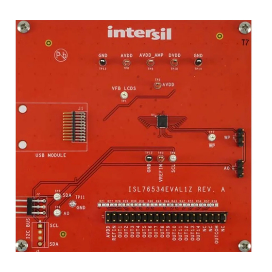
FIGURE 1. ISL76534EVAL1Z TOP VIEW
July 25, 2016
UG083.0
ISL76534
contains an
amplifier and an
COM
= 6.3V to 19V
= 2.25 to 3.6V
-Headroom
VDD
-Headroom
VDD
1
CAUTION: These devices are sensitive to electrostatic discharge; follow proper IC Handling Procedures.
1-888-INTERSIL or 1-888-468-3774
Features
• 15-Channel reference voltage outputs, I
- 14-channel gamma references, 10-bit resolution with
buffered outputs
- 1-channel V
calibrator with 10-bit resolution
COM
• High output current V
• Ultra-low power operation, ideal for tablet and mobile
applications: typical quiescent power, 12mW at 8V A
• EEPROM data retention: 20yrs at 105°C
• EEPROM endurance: 10,000 write cycles
- Read/write capable over 2.25V to 3.6V D
• 6.3V to 19V analog supply operating range
• 2.25V to 3.6V digital supply operating range
• 28 Ld 4x5mm super thin X2QFN package
• Pb-free (RoHS compliant)
•
AEC-Q100
qualified
Ordering Information
PART #
ISL76534EVAL1Z Evaluation board for the 4x5 X2QFN package
FIGURE 2. ISL76534EVAL1Z BOTTOM VIEW
|
Copyright Intersil Americas LLC 2016. All Rights Reserved
Intersil (and design) is a trademark owned by Intersil Corporation or one of its subsidiaries.
All other trademarks mentioned are the property of their respective owners.
User Guide 083
2
C programmable:
amplifier
COM
range
VDD
DESCRIPTION
VDD
Advertisement
Table of Contents

Related Manuals for Intersil ISL76534EVAL1Z


Summary of Contents for Intersil ISL76534EVAL1Z
-
Page 1: Specifications
CAUTION: These devices are sensitive to electrostatic discharge; follow proper IC Handling Procedures. 1-888-INTERSIL or 1-888-468-3774 Copyright Intersil Americas LLC 2016. All Rights Reserved UG083.0 Intersil (and design) is a trademark owned by Intersil Corporation or one of its subsidiaries. All other trademarks mentioned are the property of their respective owners. - Page 2 User Guide 083 DAC/OUTx BUFFER ANALOG DIGITAL DAC1 OUT1 POWER POWER SUPPLY SUPPLY DAC2 OUT2 DAC3 OUT3 DAC4 OUT4 OUT5 EEPROM DAC5 DAC6 OUT6 CONTROL BYTE DAC7 OUT7 14x10 DAC8 OUT8 OUT9 DAC9 DAC10 OUT10 DAC11 OUT11 INTERFACE DAC12 OUT12 DAC13 OUT13 OUT14...
-
Page 3: What Is Inside
User Guide 083 What Is Inside Initial Set-Up The evaluation kit contains: This user guide describes how to set up and use the ISL76534EVAL1Z evaluation board along with the • ISL76534EVAL1Z board ISLUSBMINIZEVAL1Z in a standalone configuration. It explains • The ISL76534... -
Page 4: Software Installation Guide
Click Next to continue to the license agreement (Figure FIGURE 7. SELECT START MENU FOLDER Click Next to create the Intersil folder in the Start menu. The Ready to Install window opens (Figure FIGURE 5. LICENSE AGREEMENT Read the license agreement, choose to accept (or not accept) the license agreement, then click Next. - Page 5 17. Turn off all supplies and disconnect the USB interface from status of the USB module hardware. the PC. If a Found New Hardware window appears asking for the location of device drivers, please contact Intersil for a new USB module. FIGURE 9. EVALUATION SOFTWARE WINDOW Submit Document Feedback UG083.0...
- Page 6 After rebooting the PC, verify that the following files are in the module. The Vendor ID = 0x09AA, and the Product ID = 0x2019. following locations: • ISL76534.exe in C:\Program Files\Intersil\ISL76534 • isilhid.dll in C:\Program Files\Intersil\ISL76534 If the dialog shown in...
- Page 7 User Guide 083 If the Vendor ID and Product ID are not visible, or if there are any • Maximize use of AC decoupled PCB layers. All signal I/O lines error messages, try the following actions: should be routed over continuous ground planes (i.e., no split planes or PCB gaps under these lines).
- Page 8 Schematic FIGURE 13. SCHEMATIC...
- Page 9 Schematic (Continued) FIGURE 14. SCHEMATIC (Continued)
-
Page 10: Bill Of Materials
(Do Not Populate), Thick Film Chip Resistor GENERIC H2511-00R00-1/16W1 R47-R50, R59 1kΩ,1%, 62.5mW, Thick Film Chip Resistor GENERIC H2511-01001-1/16W1 15Ch Programmable Gamma Buffer INTERSIL ISL76534ARXZ JP1, JP2 Three Pin Jumper GENERIC JUMPER-3-100 10/20 Pin Dual Row Header 0.5x0.5 HARWIN M50-3901042 22kΩ, 1%, 62.5mW, Thick Film Chip Resistor... -
Page 11: Pcb Layouts
User Guide 083 PCB Layouts FIGURE 15. SILK LAYER TOP FIGURE 16. TOP LAYER COMPONENT SIDE Submit Document Feedback UG083.0 July 25, 2016... - Page 12 User Guide 083 PCB Layouts (Continued) FIGURE 17. INTERNAL (LAYER 2) FIGURE 18. INTERNAL (LAYER 3) Submit Document Feedback UG083.0 July 25, 2016...
- Page 13 User Guide 083 PCB Layouts (Continued) FIGURE 19. BOTTOM LAYER SOLDER SIDE FIGURE 20. SILKSCREEN BOTTOM Submit Document Feedback UG083.0 July 25, 2016...
-
Page 14: Typical Performance Curves
FIGURE 26. DAC1-DAC15 DNL (REF = 15V) AT +105°C Intersil Corporation reserves the right to make changes in circuit design, software and/or specifications at any time without notice. Accordingly, the reader is cautioned to verify that the document is current before proceeding.
Need help?
Do you have a question about the ISL76534EVAL1Z and is the answer not in the manual?
Questions and answers