Table of Contents
Advertisement
Quick Links
ISL72813SEHEV1Z Evaluation Board User Guide
Description
The ISL72813SEHEV1Z evaluation board was designed to
provide a quick and easy method for evaluating the
ISL72813SEH, 32-channel driver circuit IC. This device is a
unique IC. To use this evaluation board properly requires a
thorough knowledge of the operation of the IC. Refer to the
ISL72813SEH
datasheet for an understanding of the functions
and features of the device.
The Intersil ISL72813SEH device is a radiation hardened,
high-voltage, high-current 32-channel driver circuit with an
integrated decoder for driving and selecting between a bank of
relays in space applications. It is fabricated using Intersil's
proprietary PR40 silicon-on-insulator process technology to
mitigate single-event effects. This device integrates 32 current
drivers that feature high-voltage, common-emitter and
open-collector outputs with a 42V breakdown voltage and
peak current rating of 600mA.
Specifications
The evaluation board has been configured and optimized for
the following conditions:
• V
= 5V
CC
• V
= -34V
EE
• Collector output (Cx) load to GND of ≥58Ω (≤600mA)
• Board temperature: +25°C
RELAY
RELAY
February 24, 2017
UG096.1
ONE FOR EACH CHANNEL
VDD
A0
A1
A2
A3
FIGURE 1. ISL72813SEHEV1Z BLOCK DIAGRAM
1
CAUTION: These devices are sensitive to electrostatic discharge; follow proper IC Handling Procedures.
1-888-INTERSIL or 1-888-468-3774
Key Features
• Toggle switches for easy control of logic pins
• LED circuitry for quick functional testing
• Convenient test points and connections for test equipment
• MCU interface connector for control of logic
• Banana jacks for power and ground connections
Related Literature
• For a full list of related documents, visit our website
-
ISL72813SEH
Datasheet
Ordering Information
PART NUMBER
ISL72813SEHEV1Z
EVALUATION BOARD
ISL72813SEH
CO
C1
C2
.
VEE
.
.
C32
6
A4
EN
|
Copyright Intersil Americas LLC 2016, 2017. All Rights Reserved
Intersil (and design) is a trademark owned by Intersil Corporation or one of its subsidiaries.
All other trademarks mentioned are the property of their respective owners.
User Guide 096
DESCRIPTION
ISL72813SEH evaluation board
+
- -34V
Advertisement
Table of Contents

Related Manuals for Intersil ISL72813SEHEV1Z


Summary of Contents for Intersil ISL72813SEHEV1Z
-
Page 1: Key Features
CAUTION: These devices are sensitive to electrostatic discharge; follow proper IC Handling Procedures. 1-888-INTERSIL or 1-888-468-3774 Copyright Intersil Americas LLC 2016, 2017. All Rights Reserved UG096.1 Intersil (and design) is a trademark owned by Intersil Corporation or one of its subsidiaries. All other trademarks mentioned are the property of their respective owners. -
Page 2: Quick Start
Access to the 32 collector driver channels is through the C0 - C31 silver turret posts. The relay load or resistor simulating the relay The ISL72813SEHEV1Z evaluation board is designed to provide a load would be connected at theses pins. Each pin in parallel to... -
Page 3: Logic Control
User Guide 096 Logic Control Test Points The ISL72813SEH IC has six logic control input pins; A0 - A4 (Pins The board has various test points for ease of connecting probes 19 - 23) and EN (Pin 25). to make measurements. The test points available are described Table The Logic 1 V level for the logic pins is from 2.0V to VCC. -
Page 4: Using The Board To Measure Vce (Sat) Vs Ivee Of Channel C0
ISL72813SEH RESISTOR DECADE DC POWER SUPPLY ISL72813SEHEV1Z REV A FIGURE 2. BASIC EVALUATION TEST SETUP BLOCK DIAGRAM (MEASURING VCE (SAT) vs ICx) Using the Board to Measure 5. Connect the resistor decade box and ammeter (A) to the C0 pin on the evaluation board as shown in Figure 2. -
Page 5: Measuring Vce (Sat) On Other Channels
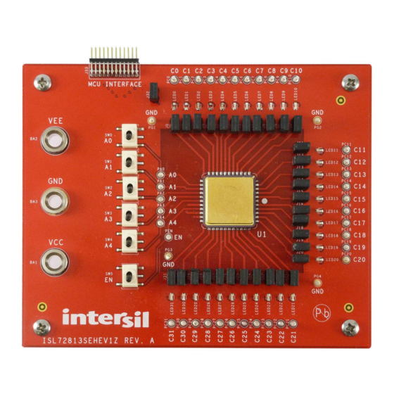
User Guide 096 Measuring VCE (SAT) on Other Channels 1. Configure the board as described in “Initial Board Setup Procedure” on page 2. Ensure that SW5 EN toggle switch is in the “L” down position to disable the IC. 3. Move the ammeter and decade box to the new Cx channel that the user wants to test. - Page 6 User Guide 096 ISL72813SEHEV1Z Evaluation Board FIGURE 3. ISL72813SEHEV1Z EVALUATION BOARD (TOP VIEW) Submit Document Feedback UG096.1 February 24, 2017...
- Page 7 User Guide 096 ISL72813SEHEV1Z Evaluation Board (Continued) FIGURE 4. ISL72813SEHEV1Z EVALUATION BOARD (BOTTOM VIEW) Submit Document Feedback UG096.1 February 24, 2017...
- Page 8 ISL72813SEHEV1Z Circuit Schematic MCU INTERFACE CONNECTOR UNNAMED_1_CONN24_I692_IN7 PC10 PC21 PC22 PC23 PC24 PC25 PC26 PC27 ISL72813SEHVL PC28 PC29 PC30 PC31 0.1UF 0.1UF -30V DRAWN BY: DATE: ENGINEER: TIM KLEMANN 12/09/2015 KIRAN BERNARD RELEASED BY: DATE: TITLE: ISL72813SEH UPDATED BY: DATE:...
- Page 9 ISL72813SEHEV1Z Circuit Schematic (Continued) UNNAMED_2_JUMPER2_I195_IN2 UNNAMED_2_JUMPER2_I204_IN2 UNNAMED_2_JUMPER2_I213_IN2 LED0 LED9 LED18 UNNAMED_2_JUMPER2_I222_IN2 LED25 UNNAMED_2_SMLED_I29_B UNNAMED_2_SMLED_I78_B UNNAMED_2_SMLED_I133_B UNNAMED_2_SMLED_I168_B 30.1K 30.1K 30.1K 30.1K UNNAMED_2_JUMPER2_I196_IN2 LED1 UNNAMED_2_JUMPER2_I205_IN2 UNNAMED_2_JUMPER2_I214_IN2 UNNAMED_2_JUMPER2_I223_IN2 LED10 LED19 LED26 UNNAMED_2_SMLED_I33_B UNNAMED_2_SMLED_I81_B UNNAMED_2_SMLED_I137_B UNNAMED_2_SMLED_I172_B 30.1K 30.1K 30.1K 30.1K UNNAMED_2_JUMPER2_I197_IN2 UNNAMED_2_JUMPER2_I206_IN2 UNNAMED_2_JUMPER2_I215_IN2 LED2...
- Page 10 User Guide 096 ISL72813SEHEV1Z Bill of Materials REFERENCE MANUFACTURER QTY UNITS DESIGNATOR DESCRIPTION PART NUMBER PA0 - PA4, PC0-PC31, Silver Solder Terminal Turret, 0.08 Pad, 0.040 Thole MILL-MAX 2108-2-00-44-00-07-0 PEN, PG1-PG4 CAP, Multilayer, 0603, 1µF, 10V, 10%, CAP_0603 MURATA GRM188R71A105KA61D CAP, Ceramic, 0803, 1µF, 50V, 10%, CAP_0805...
-
Page 11: Board Layout
User Guide 096 Board Layout FIGURE 7. SILKSCREEN TOP Submit Document Feedback UG096.1 February 24, 2017... - Page 12 User Guide 096 Board Layout (Continued) FIGURE 8. TOP LAYER COMPONENT SIDE Submit Document Feedback UG096.1 February 24, 2017...
- Page 13 User Guide 096 Board Layout (Continued) FIGURE 9. LAYER 2 Submit Document Feedback UG096.1 February 24, 2017...
- Page 14 User Guide 096 Board Layout (Continued) FIGURE 10. LAYER 3 Submit Document Feedback UG096.1 February 24, 2017...
- Page 15 User Guide 096 Board Layout (Continued) FIGURE 11. BOTTOM LAYER SOLDER SIDE Submit Document Feedback UG096.1 February 24, 2017...
- Page 16 User Guide 096 Board Layout (Continued) FIGURE 12. SILKSCREEN BOTTOM Submit Document Feedback UG096.1 February 24, 2017...
-
Page 17: Typical Performance Curves
FIGURE 15. IEE vs VEE vs TEMPERATURE Intersil Corporation reserves the right to make changes in circuit design, software and/or specifications at any time without notice. Accordingly, the reader is cautioned to verify that the document is current before proceeding.
Need help?
Do you have a question about the ISL72813SEHEV1Z and is the answer not in the manual?
Questions and answers