Table of Contents
Advertisement
Quick Links
Advertisement
Table of Contents

Related Manuals for Ubiquiti AF-11G35


Summary of Contents for Ubiquiti AF-11G35
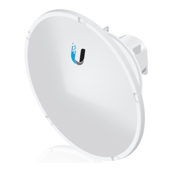
- Page 1 11 GHz, 35 dBi airFiber Dish Antenna ® Model: AF‑11G35...
-
Page 2: Package Contents
(Qty. 4) (Qty. 6) TERMS OF USE: Ubiquiti radio devices must be professionally installed. Shielded Ethernet cable and earth grounding must be used as conditions of product warranty. It is the customer’s responsibility to follow local country regulations, including operation within legal... -
Page 3: Installation Requirements
Antenna Compatibility The airFiber AF‑11G35 antenna is designed for use with the airFiber X radio model AF-11FX Installation Requirements • 13 mm wrench (pre‑assembly tool) • 17 mm wrench (pole‑mounting tool) • airFiber AF-11FX radio (sold separately) with duplexer(s) installed • Clear line of sight between airFiber radios •... -
Page 4: Hardware Overview
Hardware Overview Back Lanyard Loops Brackets Brackets Radio Mount Metal Cap RF Connector (under metal cap) RF Connector Unassembled View... - Page 5 Side Elevation Rod Hex Nut to adjust Elevation Bolts with Grounding Point Washers Assembled View...
- Page 6 The OMT (OrthoMode Transducer) is located on the back of the antenna. The default polarization is H and V. Note: If you only need to use one port, keep the other one covered with the included Metal Cap. To use ±45° slant polarization: Note: ±45°...
-
Page 7: Hardware Installation
Hardware Installation 1. Attach an RF Cable to an RF connector labeled H or V. Then slide the silicone boot over the RF connector to protect it. Note: For SISO mode, use the RF connector (H or V) as determined by your licensing. Keep the other RF connector covered with the included Metal Cap. - Page 8 3. Connect the RF Cable(s) (one in SISO mode, two in MIMO mode) to the radio as follows: • Attach the RF Cable from the H Connector to the radio’s Chain 0 connector. • Attach the RF Cable from the V Connector to the radio’s Chain 1 connector.
- Page 9 4. Attach the protective shroud. a. Align the dot on the side of the shroud with the arrow on the dish antenna. b. Guide the shroud’s tabs into the slots on the antenna. c. Push the shroud in and then pull it down until it locks into place.
- Page 10 6. Insert two Large Carriage Bolts into the Upper Mount Bracket with Elevation Rod. 7. Attach the Lower Mount Bracket to the I-Bracket using two Serrated Flange Bolts. Ensure that the slots face up and securely tighten the bolts. Proper slot orientation...
- Page 11 8. Attach the Upper Mount Bracket with Elevation Rod to the I-Bracket using two Serrated Flange Bolts. Note: Ensure that the orientation of the Upper Mount Bracket matches the illustration below, with the Elevation Rod on the correct side.
- Page 12 9. Attach the Pole Clamps to the Mount Brackets. a. Slide the slotted hole of each Pole Clamp over one upper and one lower Large Carriage Bolt. b. Place one Serrated Flange Nut on each Large Carriage Bolt.
- Page 13 10. Prepare the Azimuth Support Brackets for mounting. a. Insert the two Small Carriage Bolts into the Azimuth Support Bracket that has two slotted holes. b. Slide the slotted hole of the other Azimuth Support Bracket over one Small Carriage Bolt. c.
-
Page 14: Pole Mounting
Pole‑Mounting 1. Attach the Azimuth Support Brackets to the pole just beneath the area where the airFiber radio will be attached. Note: The mounting assembly can accommodate a Ø 38.1 ‑ 101.6 mm (1.5" ‑ 4.0") pole. a. Orient the Azimuth Support Brackets around the pole so it is aimed in the direction of the other airFiber radio. - Page 15 2. Attach the mounting assembly to the pole. a. Orient the mounting assembly around the pole so it is aimed in the direction of the other airFiber radio. b. Slide the open slot of each Pole Clamp over the corresponding Large Carriage Bolt. c.
- Page 16 3. Lift the airFiber antenna and align the two lower Bolts with Washers with the slots on the Lower Mount Bracket. Seat the bolts in the slots.
- Page 17 4. Align the two upper Bolts with Washers of the airFiber antenna next to the slots on the Upper Mount Bracket. Lift the airFiber radio and seat the bolts in the slots. 5. Secure the free end of the ground wire to a grounded mast, pole, tower, or grounding bar.
- Page 18 6. Visually align the azimuth and elevation. a. To adjust the azimuth, rotate the antenna while it is supported by the Stabilizer Brackets. b. To adjust the elevation angle, tighten or loosen the nuts on the Elevation Rod so that the Dish Reflector is set to the desired tilt.
-
Page 19: Specifications
Specifications airFiber AF‑11G35 Dimensions 811 x 811 x 460 mm (31.9 x 31.9 x 18.1") Weight 16.5 kg (36.38 lb) Frequency 10.3 to 11.7 GHz Gain 35 dBi HPOL Beamwidth 2.5° VPOL Beamwidth 2.5° Maximum VSWR Wind Survivability 200 km/h (125 mph) Wind Loading 1538 N @ 200 km/h Polarization... -
Page 20: Safety Notices
Safety Notices Read, follow, and keep these instructions. Heed all warnings. Only use attachments/accessories specified by the manufacturer. WARNING: Do not use this product in location that can be submerged by water. WARNING: Avoid using this product during an electrical storm. -
Page 21: Limited Warranty
(VI) has no original Ubiquiti MAC label, or is missing any other original Ubiquiti label(s); or (VII) has not been received by Ubiquiti within 30 days of issuance of the RMA. - Page 22 No Products will be accepted for replacement or repair without obtaining a Return Materials Authorization (RMA) number from UBIQUITI NETWORKS during the warranty period, and the Products being received at UBIQUITI NETWORKS’ facility freight prepaid in accordance with the RMA process of UBIQUITI NETWORKS.
-
Page 23: Limitation Of Liability
Limitation of Liability EXCEPT TO THE EXTENT PROHIBITED BY LOCAL LAW, IN NO EVENT WILL UBIQUITI OR ITS SUBSIDIARIES, AFFILIATES OR SUPPLIERS BE LIABLE FOR DIRECT, SPECIAL, INCIDENTAL, CONSEQUENTIAL OR OTHER DAMAGES (INCLUDING LOST PROFIT, LOST DATA, OR DOWNTIME COSTS), ARISING... - Page 24 RoHS/WEEE Compliance Statement English European Directive 2012/19/EU requires that the equipment bearing this symbol on the product and/or its packaging must not be disposed of with unsorted municipal waste. The symbol indicates that this product should be disposed of separately from regular household waste streams.
- Page 25 Español La Directiva 2012/19/UE de la UE exige que los equipos que lleven este símbolo en el propio aparato y/o en su embalaje no deben eliminarse junto con otros residuos urbanos no seleccionados. El símbolo indica que el producto en cuestión debe separarse de los residuos domésticos convencionales con vistas a su eliminación.
-
Page 26: Declaration Of Conformity
[German] Anforderungen und den anderen relevanten Vorschriften der Richtlinie 1999/5/EG befindet. Ελληνική Δια του παρόντος, UBIQUITI NETWORKS, δηλώνει ότι αυτή η συσκευή UBIQUITI NETWORKS, είναι σε συμμόρφωση με τις [Greek] βασικές απαιτήσεις και τις λοιπές σχετικές διατάξεις της οδηγίας 1995/5/ΕΚ. - Page 27 NETWORKS zariadenie, je v súlade so základnými požiadavkami a [Slovak] ďalšími relevantnými ustanoveniami smernice 1999/5/ES. Español Por medio de la presente UBIQUITI NETWORKS declara que este dispositivo UBIQUITI NETWORKS, cumple con los requisitos [Spanish] esenciales y cualesquiera otras disposiciones aplicables o exigibles de la Directiva 1999/5/CE.
-
Page 28: Online Resources
©2016 Ubiquiti Networks, Inc. All rights reserved. Ubiquiti, Ubiquiti Networks, the Ubiquiti U logo, the Ubiquiti beam logo, airFiber, and airOS are trademarks or registered trademarks of Ubiquiti Networks, Inc. in the United States and in other countries. All other trademarks are the property of their respective owners.
Need help?
Do you have a question about the AF-11G35 and is the answer not in the manual?
Questions and answers