Ubiquiti AirFiber X AF-5G34-S45 Quick Start Manual
5 ghz, 34 dbi slant 45 antenna
Hide thumbs
Also See for AirFiber X AF-5G34-S45:
- Quick start manual (18 pages) ,
- Quick start manual (18 pages)
Table of Contents
Advertisement
Advertisement
Table of Contents

Subscribe to Our Youtube Channel
Related Manuals for Ubiquiti AirFiber X AF-5G34-S45


Summary of Contents for Ubiquiti AirFiber X AF-5G34-S45
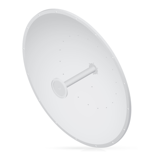
- Page 1 5 GHz, 34 dBi Slant 45 Antenna for airFiber ® Model: AF-5G34-S45...
-
Page 2: Package Contents
(Qty. 3) (Qty. 6) Guide TERMS OF USE: Ubiquiti radio devices must be professionally installed. Shielded Ethernet cable and earth grounding must be used as conditions of product warranty. TOUGHCable ™ is designed for outdoor installations. It is the customer’s responsibility to follow local country regulations, including operation within legal frequency channels, output power, and Dynamic Frequency Selection (DFS) requirements. -
Page 3: Installation Requirements
Installation Requirements • airFiber AF‑5X radio (sold separately) • Phillips #1 screwdriver • 16 mm wrench • 24 mm wrench • Mounting point: • At least 1 m below the highest point on the structure • For tower installations, at least 3 m below the top of the tower •... -
Page 4: Installation
Installation Important: Handle the Dish Reflector with care. Deformations in its shape may reduce the antenna's effectiveness. 1. Each M4 Bolt includes a lock washer. Remove these and use them to secure the bolts when assembling. 2. The Dish Reflector and Antenna Feed are keyed so the Antenna Feed can only be installed in a single orientation. - Page 5 3. Attach the RF Cables to the connectors labeled Chain 0 and Chain 1 on the airFiber radio. 4. Attach the airFiber radio to the Dish Reflector. a. Align the mounting tabs on the back of the airFiber radio with the airFiber radio mount located below the Antenna Feed.
- Page 6 5. Attach the other end of the RF Cables to the RF connectors on the airFiber radio in this combination: +45° to Chain 0 and -45° to Chain 1. Then slide the jackets over the RF connectors to protect them. 6. Attach the external GPS antenna (included with the airFiber radio) to the RF connector labeled GPS on the airFiber radio.
- Page 7 7. Attach the Protective Shroud. a. Align the arrow on the top of the shroud with the short hash mark on the Dish Reflector. b. Rotate the shroud clockwise until it aligns with the long hash mark to lock into place. 8.
- Page 8 10. Each M12x180 Carriage Bolt includes a flat washer, spring lock washer, and nut. Remove these and use them to secure the bolts when assembling in step 16. 11. Insert the four M12x180 Carriage Bolts into the Mounting Bracket.
- Page 9 12. Each M10x25 Carriage Bolt includes a flat washer, spring lock washer, and nut. Remove these and use them to secure the bolts when assembling. 13. Attach the antenna to the Mounting Bracket. a. Insert one M10x25 Carriage Bolt into the antenna and Elevation Rod.
- Page 10 14. Each M10x100 Bolt includes a flat washer, spring lock washer, and nut. Remove these and use them to secure the bolts when assembling. 15. Attach the Stabilizer Brackets to the pole just beneath the area where the antenna will be attached. Note: The mounting assembly can accommodate a Ø...
- Page 11 16. Attach the Mounting Bracket to the pole just above the Stabilizer Brackets. a. Slide a Pole Clamp over each pair of M12x180 Carriage Bolts. b. Secure each M12x180 Carriage Bolt with one flat washer, one spring lock washer, and one nut.
- Page 12 17. Visually align the azimuth and elevation. a. To adjust the azimuth, rotate the antenna while it is supported by the Stabilizer Brackets. b. To adjust the elevation angle, tighten or loosen the nuts on the Elevation Rod so that the antenna is set to the desired tilt.
-
Page 13: Mounting The External Gps Antenna
Mounting the External GPS Antenna Locate a mounting point that has a clear view to the sky, and is above and as far away as possible from the antenna. Note: All GPS items are included with the airFiber radio. 1. Attach the GPS antenna mount to the pole using the metal strap, or attach it to a wall using the appropriate fasteners (not included). -
Page 14: Specifications
Specifications AF‑5G34‑S45 Dimensions 1050 x 1050 x 421 mm (41.34 x 41.34 x 16.57") Weight 13.5 kg (29.76 lb) (Mount Included) Frequency 5.1 ‑ 5.8 GHz Gain 34 dBi Max. VSWR 1.4:1 Wind Survivability 200 km/h (125 mph) Wind Loading 1,779 N @ 200 km/h (400 lb @ 125 mph) Polarization Dual Linear... -
Page 15: Safety Notices
Safety Notices Read, follow, and keep these instructions. Heed all warnings. Only use attachments/accessories specified by the manufacturer. WARNING: Do not use this product in location that can be submerged by water. WARNING: Avoid using this product during an electrical storm. -
Page 16: Limited Warranty
(VI) has no original Ubiquiti MAC label, or is missing any other original Ubiquiti label(s); or (VII) has not been received by Ubiquiti within 30 days of issuance of the RMA. -
Page 17: Limitation Of Liability
SUBJECT TO LIMITATIONS, INTERRUPTIONS, DELAYS, CANCELLATIONS AND OTHER PROBLEMS INHERENT IN THE USE OF COMMUNICATIONS FACILITIES. UBIQUITI NETWORKS, ITS AFFILIATES AND ITS AND THEIR THIRD PARTY PROVIDERS ARE NOT RESPONSIBLE FOR ANY INTERRUPTIONS, DELAYS, CANCELLATIONS, DELIVERY FAILURES, DATA LOSS, CONTENT CORRUPTION, PACKET LOSS, OR OTHER DAMAGE RESULTING FROM ANY OF THE FOREGOING. - Page 18 Note Some countries, states and provinces do not allow exclusions of implied warranties or conditions, so the above exclusion may not apply to you. You may have other rights that vary from country to country, state to state, or province to province. Some countries, states and provinces do not allow the exclusion or limitation of liability for incidental or consequential damages, so the above limitation may not apply to you.
- Page 19 Compliance RF Exposure Warning The antenna and transmitter must be installed to provide a separation distance from all persons and must not be located or operating in conjunction with any other antenna or transmitter. For the specific separation distance, refer to the Quick Start Guide for your airFiber radio device (transmitter).
- Page 20 RoHS/WEEE Compliance Statement English European Directive 2002/96/EC requires that the equipment bearing this symbol on the product and/or its packaging must not be disposed of with unsorted municipal waste. The symbol indicates that this product should be disposed of separately from regular household waste streams.
- Page 21 Español La Directiva 2002/96/CE de la UE exige que los equipos que lleven este símbolo en el propio aparato y/o en su embalaje no deben eliminarse junto con otros residuos urbanos no seleccionados. El símbolo indica que el producto en cuestión debe separarse de los residuos domésticos convencionales con vistas a su eliminación.
-
Page 22: Declaration Of Conformity
UBIQUITI NETWORKS device, megfelel a vonatkozó alapvetõ [Hungarian] követelményeknek és az 1999/5/EC irányelv egyéb elõírásainak. Íslenska Hér me l sir UBIQUITI NETWORKS yfir ví a UBIQUITI NETWORKS device, er í samræmi vi grunnkröfur og a rar kröfur, sem ger ar eru í [Icelandic] tilskipun 1999/5/EC. -
Page 23: Online Resources
[Swedish] egenskapskrav och övriga relevanta bestämmelser som framgår av direktiv 1999/5/EG. Español Por medio de la presente UBIQUITI NETWORKS declara que el UBIQUITI NETWORKS device, cumple con los requisitos esenciales [Spanish] y cualesquiera otras disposiciones aplicables o exigibles de la Directiva 1999/5/CE. - Page 24 . u b n t . c o m ©2015 Ubiquiti Networks, Inc. All rights reserved. Ubiquiti, Ubiquiti Networks, the Ubiquiti U logo, the Ubiquiti beam logo, airFiber, and TOUGHCable are trademarks or registered trademarks of Ubiquiti Networks, Inc. in the United States and in other countries.
Need help?
Do you have a question about the AirFiber X AF-5G34-S45 and is the answer not in the manual?
Questions and answers