Table of Contents
Advertisement
Quick Links
M
MC600
ODEL
Multi-Channel Controller
for Hydrocarbon, H
S and Toxic
2
Gas Monitoring Applications
The information and technical data disclosed in
this document may be used and disseminated
only for the purposes and to the extent
specifically authorized in writing by General
Monitors.
Instruction Manual
12-15
General Monitors reserves the right to change
published specifications and designs without
prior notice.
Part No.
MANMC600
Revision
T/12-15
Advertisement
Table of Contents

Related Manuals for MSA General Motions MC600


Summary of Contents for MSA General Motions MC600
- Page 1 MC600 ODEL Multi-Channel Controller for Hydrocarbon, H S and Toxic Gas Monitoring Applications The information and technical data disclosed in this document may be used and disseminated only for the purposes and to the extent specifically authorized in writing by General Monitors.
-
Page 2: Warnings
Model MC600 Warranty General Monitors warrants the Model MC600 to be free from defects in workmanship or material under normal use and service within two (2) years from the date of shipment. General Monitors will repair or replace without charge any such defective equipment found to be deficient during the warranty period. -
Page 3: System Integrity Verification
Model MC600 System Integrity Verification General Monitors’ mission is to benefit society by providing solutions through industry-leading safety products, services, and systems that save lives and protect capital resources from the dangers of hazardous flames, gases, and vapors. The safety products you have purchased should be handled carefully and installed, calibrated, and maintained in accordance with their product instruction manuals. -
Page 4: Periodic System Verification
Model MC600 Periodic System Verification The following system verifications should be performed at least annually: Verify wiring, terminal connections and stability of mounting for all integral safety equipment, including, but not limited to: Power supplies Control modules Field detection devices ... -
Page 5: About This Manual
Model MC600 About This Manual This manual provides instructions for installing and operating the Model MC600 Multi-Channel Controller. Maintenance and specification information is also provided, as well as, programming information for the MODBUS registers. The intended audience includes field service technicians, MODBUS programmers and other technical staff involved in installing and using an MC600 system. -
Page 6: Related Documentation
Model MC600 Related Documentation The detection instruments that you connect to the MC600 each have their own documentation and you will need to refer to the instruction manual for each instrument in order to calibrate and maintain the instrument. A list of the manuals for the MC600-compatible detection instruments follows: ... -
Page 7: Quick Start Installation Instructions
Model MC600 1.0 Quick Start Installation Instructions The main steps in a typical MC600 installation are listed below. There is some variation in the installation process at each site, depending on the exact site configuration. Installation Step Refer to Section 1. - Page 8 Model MC600 NOTE: Each Model MC600 is thoroughly tested at the factory. However, a system checkout is required upon initial start-up to ensure system integrity. Preparing for the Installation To prepare installing the MC600 cabinet, you will need to choose a location and gather the required tools.
- Page 9 Model MC600 Mounting the MC600 Cabinet in Place Figure 1: Mounting Dimensions for the MC600 Cabinet Before bolting the cabinet in place, make sure it is level. Fasten four ¼-inch bolts into the four mounting holes on the corners of the enclosure. Use appropriate mounting screws/bolts in regard to the mounting surface i.e.
- Page 10 Model MC600 1.4.1 Mounting Sensors with General Monitors’ Accessories Section 11.0 provides ordering information for several accessories for sensor mounting, such as explosion-proof junction boxes, duct mounting kits, splashguards, dust guards and remote calibration devices. Instructions for mounting each type of 4-20mA instrument are provided in the instruction manual for the instrument.
- Page 11 Model MC600 CAUTION: Under no circumstances should equipment be connected or disconnected when under power. This is contrary to hazardous area regulations and may also lead to serious damage to the equipment. Equipment damaged in this manner is not covered under warranty.
- Page 12 Model MC600 Three-wire or four-wire cabling is used to connect from the catalytic HC signal- conditioning card to a field-mounted catalytic HC sensor. The maximum cable lengths are indicated in Table 26; Catalytic HC Sensor Cable Lengths. To connect a catalytic HC sensor: 1.
- Page 13 Model MC600 NOTE: When the field instrument is an IR5000/IR5500, there are two Analog Out signals from the field instrument. Connect them to the Analog In receptacles of any two channels of the MC600 system. COM (DC Ground) must also be connected from the field device to the MC600 signal-conditioning card connector.
- Page 14 Model MC600 CAUTION: The MC600 Multi-Channel Controller System cannot provide sufficient power for an IR5000/IR5500 field instrument. When an IR5000/IR5500 is being connected to the MC600, the user should provide their own 24V power supply for the IR5000/IR5500 source and receiver units, as outlined in the IR5000/IR5500 manual. Do not use the +24V DC signal connection from the MC600 signal- conditioning card, or damage to the system may occur.
- Page 15 Model MC600 If the relays are set up as de-energized (the default), the last digit 1 is for normally closed and the last digit 2 is for normally open. If the relays are set up as energized, the last digit 1 is normally open and the last digit 2 is normally closed.
- Page 16 Model MC600 NOTE: The +24V wire(s) to the power supply (supplies) should be connected after the readiness checklist is verified to protect the system from shorting. NOTE: The SHIELD terminal of J9 should be connected to an earth ground. 1.9.2 Connecting the MC600 to a Power Supply WARNING: The MC600 power supply or connected external power supply should be left OFF and unconnected to its power source until after...
- Page 17 Model MC600 Figure 8: Onboard Class I Division 2 Power Supply To connect the MC600 onboard Class I Division 2 power supply to a power source: Refer to Figure 10 when following these steps 3. Connect cabling from the connector beneath the power supply to the power supply’s external power source.
- Page 18 Model MC600 Figure 9: MC600 Connections to an External Power Supply Refer to Figure 11 when following these steps 1. Connect a wire from the MC600 J9 connector COM receptacle to the power supply DC Ground connector. 2. Connect the MC600 J9 connector +24VDC receptacle to the power supply +24VDC terminal 3.
- Page 19 Model MC600 1.9.3 Startup Process for an MC600 System Upon power-up, the MC600 only requires a few minutes to stabilize while the unit attains proper operation. The six MC600 channel LCDs will go through the following process during this period: 1.
- Page 20 Model MC600 For each MOS H S sensor connected to the MC600, General Monitors recommends that you calibrate the sensor one hour after start-up and again 24 hours later. 3. Recalibrate the LCD channel display for 4-20mA signal-conditioning cards (Section 4.6). 4.
-
Page 21: Table Of Contents
Model MC600 Table of Contents WARRANTY ..........................II WARNINGS ..........................II SYSTEM INTEGRITY VERIFICATION..................III Commissioning Safety Systems ....................iii Periodic Testing/Calibration of Field Devices ................iii Periodic System Verification ..................... iv ABOUT THIS MANUAL ......................V Format Conventions ..........................v Notes, Cautions and Warnings .................... - Page 22 Model MC600 Preparing for the Installation ...................... 5 3.2.1 Choosing a Location ..................... 5 3.2.2 Tools You Will Need ..................... 5 Mounting the MC600 Cabinet in Place ..................6 Mounting the Sensors and Instruments ..................7 3.4.1 Sensor Location Considerations ................... 7 3.4.2 Sensor Poisons ......................
- Page 23 Model MC600 5.1.5 Configuring Card Tests ....................59 5.1.6 Configuring Setup and Inhibit Passwords ..............60 5.1.7 Configuring the Fault Relays ..................62 5.1.8 Configuring MODBUS Parameters ................63 5.1.9 Loading Default Settings ..................... 64 Using the Setup Check Menu ....................65 Using the Self Test Menu ......................
- Page 24 Model MC600 9.3.7 Temperature (0007h, Read-Only) ................87 9.3.8 Maximum Temperature (0008h, Read-Only) .............. 87 9.3.9 Minimum Temperature (0009h, Read-Only) ............... 87 9.3.10 Accept/Reset (000Ah, Write-Only) ................87 9.3.11 MODBUS Channel 1 Address (000Fh, Read/Write) ........... 87 9.3.12 MODBUS Channel 1 Baud Rate (0010h, Read/Write) ..........88 9.3.13 MODBUS Channel 1 Data Format (0011h, Read/Write) ..........
- Page 25 Model MC600 10.3 Environmental Specifications ....................105 10.4 Electrical Specifications ......................105 10.4.1 Relay Ratings ......................106 10.4.2 RS-485 Output ......................106 10.5 Approvals ..........................106 11.0 SENSORS AND ACCESSORIES ................. 107 11.1 Catalytic Bead Hydrocarbon (HC) Sensors ................107 11.2 Catalytic HC Sensor Spare Parts and Accessories ...............
- Page 26 Model MC600 Table of Figures Figure 1: Mounting Dimensions for the MC600 Cabinet ..................ix Figure 2: Pre-stripping Wiring ..........................x Figure 3: MOS H S Connection ..........................xi Figure 4: 4-20mA Instrument Connection ......................xii Figure 5: Cabling Shield ............................xiii Figure 6: MC600 MODBUS &...
- Page 27 Model MC600 Figure 51: H S Portable Purge Calibrator ......................71 Figure 52: Outline and Dimensional Drawing ..................... 103 Figure 53: Outline and Dimension Drawing, Cabinet Door and Bottom ............. 104 Figure 54: Catalytic Bead, Combustible Gas Sensor ..................107 Figure 55: MOS H S Gas Sensor ........................
- Page 28 Model MC600 Table of Tables Table 1: MC600 Installation Overview ........................vii Table 2: Normally Open and Closed Relays ......................xv Table 3: MC600 Installation Overview ........................4 Table 4: Normally Open and Closed Relay Contacts ................... 17 Table 5: MC600 Device Measurement Ranges, Minimum and Maximum Set Points and Increments ....44 Table 6: Default Allocation of Relays to Channels and Alarms ................
-
Page 29: Figure 10: Mc600 Multi Channel Controller System
Model MC600 2.0 Introduction This manual provides instructions for installing and operating the Model MC600 Multi-Channel Controller System for gas detection. Task procedures for installation, menu-based configuration, and operation are provided, along with, maintenance instructions, specifications, MODBUS programming information. The MC600 is a microprocessor-based controller that provides six channels of continuous gas detection. -
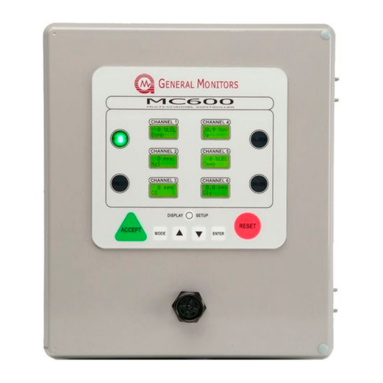
Page 30: Figure 11: Mc600 Cabinet Front Panel And Interior
Model MC600 Once sensors and instruments are connected to the MC600 signal cards via cabling, you can set up and monitor the devices using the MC600 front panel LCD displays and menu controls (or using the MODBUS communications interface). The six backlit LCD modules have two lines each, with eight characters per line. - Page 31 Model MC600 Features and Benefits The following is a partial list of features and benefits for the MC600 Multi- Channel Controller System: Gas detection and calibration control Stored detector and gas table information for the General Monitors’ catalytic HC and MOS H S sensors.
-
Page 32: Unpacking The Mc600 Equipment
Model MC600 3.0 Installation The main steps in a typical MC600 installation are listed below. There is some variation in the installation process at each site, depending on the exact site configuration. Installation Step Refer to Section 1. Unpack the equipment and prepare for the installation. Section 3.1 and Section 3.2 2. -
Page 33: Preparing For The Installation
Model MC600 All equipment shipped by General Monitors is packaged in shock absorbing containers, which provide considerable protection against physical damage. The contents should be carefully removed and checked against the packing list. If any damage has occurred or there is any discrepancy in the order, please notify General Monitors as soon as possible. -
Page 34: Mounting The Mc600 Cabinet In Place
Model MC600 Mounting the MC600 Cabinet in Place Once the MC600 cabinet is prepared for installation, it should be mounted in place. Figure 12: Mounting Dimensions for the MC600 Cabinet Before bolting the cabinet in place, make sure it is level. Fasten four ¼-inch bolts into the four mounting holes on the corners of the enclosure. -
Page 35: Mounting The Sensors And Instruments
Model MC600 Mounting the Sensors and Instruments The gas detection devices that will be connected to the MC600 must be mounted in locations where they are needed for gas detection. This can take place either before or after the MC600 cabinet is mounted in place. ... -
Page 36: Mounting A Sensor With A Gm Junction Box
Model MC600 Other damaging materials that can harm the sensor include mineral acids and caustic vapors. The presence of such poisons and vapors does not exclude the use of MOS H S and catalytic HC sensors; however, a careful analysis of ambient conditions should be undertaken and the customer should be aware that sensor calibration might need to occur at more frequent intervals. -
Page 37: Applying Sealants To Conduit Entries
Model MC600 3.4.4 Mounting a Sensor with a Duct Mounting Kit General Monitors produces a Duct Mounting Kit (P/N 10041) for applications that require the sensor to be mounted in an air-conditioning system or heating duct. Figure 14: Duct Mounting Kit Assembly To install a sensor using the Duct Mounting Kit Assembly: 1. -
Page 38: Connecting Sensors And Instruments To The Mc600
Model MC600 General Monitors are for dust protection only and must not be left on the unit when installed. CAUTION: Acetic acid will cause damage to metal components, metal hardware, ceramic IC’s, etc. If damage results from the use of a sealant that contains acetic acid (RTV silicone), the warranty will be void. -
Page 39: Warnings, Cautions And Standards
Model MC600 3.5.1 Warnings, Cautions and Standards Please review the following warning and caution statements before proceeding to install cabling. For information on non-hazardous location cabling to the MC600 cabinet, see NEC article 504. For information on Class I location seals for sensors mounted in hazardous areas, see NEC articles 501-5 and 500-3d WARNING: Under no circumstances should equipment be connected or... -
Page 40: Connecting A Mos H
Model MC600 3.5.2 Connecting a MOS H S Sensor to the MC600 CAUTION: Only MOS H S sensors designed by General Monitors will work with the MC600. Any attempt to use a sensor that has not been designed by General Monitors will void the MC600 warranty. Four-wire cabling is required to connect from the MOS H2S signal-conditioning card to a field-mounted MOS H2S sensor. -
Page 41: Connecting A Catalytic Hc Sensor To The Mc600
Model MC600 4. Once the wires are secured in the connector, replace the connector on the card and tighten the connector mounting screws at each side. 5. The fuse on the signal conditioning card may need to be replaced if a sensor fault error appears during power-on (Section 8.2.7) 3.5.3 Connecting a Catalytic HC Sensor to the MC600 CAUTION: Only catalytic HC sensors designed by General Monitors will work... -
Page 42: Connecting A 4-20Ma Instrument To The Mc600
Model MC600 4. Once the wires are secured in the connector, replace the connector on the card and tighten the connector mounting screws at each side. NOTE: If you have four-wire cabling, you can fasten the green wire into the empty second receptacle;... -
Page 43: Figure 21: Connector Receptacle
Model MC600 Cable from Instrument Shield Analog Out Ground COM- Ground (+24VDC) Analog In Wire Receptacle Screws 63 mA Fuse (250 Volts) 500 mA Fuse (250 Volts) Figure 21: Connector Receptacle The Analog Out signal from the detection instrument must be routed to the Analog In receptacle on the signal conditioning card connector. -
Page 44: Connecting A Modbus Device
Model MC600 and receiver units as outlined in the IR5000/IR5500 manual. Do not use the +24V DC signal connection from the MC600 signal- conditioning card, or damage to the system may occur. Connecting a MODBUS Device Connector J8 near the bottom left side of the MC600 main circuit board is provided for connecting the two MC600 MODBUS channels to control room MODBUS devices. -
Page 45: Figure 22: Mc600 Modbud & Alarm Relay Connectors
Model MC600 Figure 22: MC600 MODBUD & Alarm Relay Connectors There are three receptacles in connectors J10 and J11 to connect each of six relays, for a total of 18 receptacles. Each receptacle label indicates what it is used for. The first digit in the receptacle label represents the channel number, from 1 to 6. -
Page 46: Connecting Power And Starting Operation
Model MC600 WARNING: Relay contacts must be protected against transient and over-voltage conditions (Figure 27). Figure 23: Relay Protection for DC and AC Loads European Union (EU) Approved Applications: The ALARM relay contact ratings are 8A, 30 V RMS/42.4 V peak or 8A @ 30 VDC resistive max. North American Approved Applications: The ALARM relay contact ratings are 8A @ 250 VAC and 8A @ 30 VDC resistive max. -
Page 47: Connecting The Mc600 To A Power Supply
Model MC600 3.9.2 Connecting the MC600 to a Power Supply WARNING: The MC600 power supply or connected external power supply should be left OFF and unconnected to its power source until after you have completed cabling connections. 4. If you have ordered a power supply pre-installed for the MC600, then the unit is shipped with cabling from the power supply to the control board pre-installed. -
Page 48: Figure 25: Onboard Class I Division 2 Power Supply
Model MC600 Figure 25: Onboard Class I Division 2 Power Supply To connect the MC600 Class I Division 2 onboard power supply to an power source: Refer to Figure 25 when following these steps 3. Connect cabling from the connector beneath the power supply to the power supply’s external power source. -
Page 49: Startup Process For An Mc600 System
Model MC600 Figure 26: MC600 Connections to an External Power Supply You will need to refer to your power supply manual for the location of the ground and +24VDC terminals, and connections from the external power supply to a power source. Refer to Figure 26 as you follow these steps. - Page 50 Model MC600 Upon first power-up, the MC600 requires a few minutes to stabilize while the unit attains its proper operating temperature. The six MC600 Channel LEDs will go through the following process during this period: 1. The LCD segments for all six channels remain lit for several seconds. The four LEDs for READY, ALARM, FAULT and WARN also remain lit during this period.
-
Page 51: Figure 27: Sample Operation Mode Display
Model MC600 Catalytic HC Sensor TS400 or IR7000 (or HC Instruments) Carbon Monoxide Instrument 0% LEL 0 ppm MOS H S Sensor Comb or H S Instruments such as S4000T) Same as Channel 1 0 ppm 0% LEL Comb TS420 Oxygen TS4000 Chlorine Instrument Dioxide Instrument... -
Page 52: Configuring The Front Panel Setup
Model MC600 3.10 Configuring the Front Panel Setup Use the button to adjust the front panel LCD displays, LEDs [DISPLAY SETUP] and sounder (if installed). The following flowchart shows the front panel setup options that appear in the Channel 1 display. The changes you select using this menu will affect all six LCD displays, all four LEDs, etc. -
Page 53: Maintaining The X/P Integrity
Model MC600 3.11 Maintaining the X/P Integrity The catalytic HC and MOS H S sensor junction box housings are rated explosion-proof for use in the following hazardous locations: CSA/FM: Class I, Division 1, Groups B, C, D and Class I, Zone 1. ATEX: Ex e d IIC, II 2 G Anytime the cover of a sensor housing is removed, or the cover bolts are loosened and power is to be left on, it will be necessary to declassify the area. -
Page 54: Basic Operation And Configuration
Model MC600 4.0 Basic Operation and Configuration The MC600 LCD displays and navigation buttons form the user interface for a set of menu options that provide you with the most flexible gas detection system possible. This chapter describes how to use the MC600 menus for operation and configuration of the MC600 system unit and connected sensors and instruments. -
Page 55: Using The Front Panel Navigation Buttons
Model MC600 Pressing the button a second time returns all six channels to [MODE] Operation mode, exiting from the menus. If you have made changes to the configuration settings using the menus, the prompt Save ? Yes appears when you press the button a second time;... -
Page 56: Mc600 Menu Overview
Model MC600 MC600 Menu Overview The following illustration shows an overview of the upper branches of the MC600 menus. Figure 30 shows a navigational flowchart for the two-line LCD menu options as they appear on the Channel 1 LCD display. Variables you must select are shown in italics, such as Chan # 1-6, etc. -
Page 57: Calibrating Catalytic Hc And Mos H S Sensors
Model MC600 Following are descriptions of the six main menu options; each option has one or more submenus branching from it. 1. Calibration Menu (Menu Cal). Use this option to select an MC600 channel and place it in Calibration Mode. Section 4.5 describes how to use this option to calibrate catalytic HC and MOS H S sensors connected to an MC600 channel, to improve their gas... -
Page 58: Calibration Schedule
Model MC600 NOTE: 4-20mA instruments must be calibrated with their own control devices rather than using the MC600 menus. However, you can use the Menu Cal option to calibrate the LCD display for these instruments (see Section 4.6). 4.5.1 Calibration Schedule For catalytic HC sensors connected to the MC600, General Monitors recommends that you calibrate the sensor one hour after a first time system start-up. -
Page 59: Figure 31: Portable Purge Calibration Equipment
Model MC600 4.5.3.1 Equipment for Catalytic HC Sensors The recommended calibration equipment for GM catalytic HC sensors is a GM portable purge calibrator (Figure 34). Figure 31: Portable Purge Calibration Equipment Before beginning sensor calibration, you should place the calibration cup over the sensor;... -
Page 60: Calibration Procedure For Catalytic Hc And Mos H
Model MC600 Figure Figure 32: Field Calibrator (Breaker Bottle) with H S Gas Ampoule The glass ampoules contain an H S gas concentration that is 50% of full-scale for the sensor that will be calibrated; ampoules containing several different concentrations of S gas are available for different sensor models. -
Page 61: Stopping Sensor Calibration
Model MC600 4. When the message Apply Gas appears on the LCD display, you should apply gas to the sensor. You have six minutes to apply gas and complete the calibration process. First make sure that the device supplying gas for calibration is fastened in place over the sensor;... -
Page 62: Calibrating The Lcd Display For 4-20Ma Instruments
Model MC600 Calibrating Display 4-20mA Instruments NOTE: You cannot calibrate a 4-20mA instrument using the MC600 menus or MODBUS commands; you must calibrate and apply gas using the instrument’s onboard controller, following the directions in the Instruction Manual for the instrument. The MC600 displays a value that is proportional to the current value that it receives from connected 4-20mA instruments. -
Page 63: Checking Calibration For Sensors
Model MC600 5. The messages for oxygen detection instruments such as the TS420 are different, since an oxygen sensor outputs 17.38mA by default. They appear as follows: 4-20 Crd Spanning: A 17.38mA current input is calibrated to display as 20.9%. Remove Cell: You will need to remove the sensor cell from the TS420 instrument to cause the current to go to 3.50mA. - Page 64 Model MC600 To Run a Calibration Check for a Catalytic HC or MOS H S Sensor: 1. Press the [ button to exit from Operation Mode and enter the MC600 MODE] menus. The main menu option Menu Cal appears. 2. Press [] to move to the Menu Cal Chck option. Press [ to move to ENTER] the Calchck Chan # 1 prompt.
-
Page 65: Inhibiting Alarms For Selected Channels
Model MC600 NOTE: The default gas concentration level for calibrating all GM sensors is 50% of full-scale. You can change this default for catalytic HC sensors only via the Cal Pnt menu option. 7. Once you have pressed to begin calibration, the message Cal in [ENTER] Progress flashes on the LCD display. -
Page 66: Using The Basic Setup Menu Options
Model MC600 To Restore an Inhibited Alarm: 1. Press the [ button to exit from Operation Mode and enter the MC600 MODE] menus. The first main menu option Menu Cal appears. 2. Press [] to move to the option Menu Inhibit Press [ to move to the ENTER]... -
Page 67: Figure 33: Setup Channels Submenu
Model MC600 Menu Setup ENTER Enter Password ENTER Setup Channels ENTER Channel Channel Channel Channel Channel Channel RESET RESET RESET RESET RESET ENTER ENTER ENTER ENTER ENTER RESET ENTER ... -
Page 68: Configuring Alarm And Warning Set Points
Model MC600 Options Options Options Options Options Adjust Mode Alarms Delays Cal Pnt RESET ENTER ENTER See Figure 37 See Section 4.6 See Section 5 for Delay Delay Delay Delay ... - Page 69 Model MC600 The default setting for the Alarm High set point is always 60% of the full-scale (maximum display) value, as calculated in %LEL, %v/v or ppm units. The Alarm Low set point for all sensors and instruments must be less than or equal to the Alarm High set point, and greater than or equal to the Warning set point.
- Page 70 Model MC600 Sensor / Instrument Model Display Display Warning Alarm High Set point Value Full Increment Min. Set Max. Set point Increment Range point TS400, H S, 20 0-20 ppm 0.1 ppm 1 ppm 19 ppm 0.1 ppm TS400, H S, 50 0-50 ppm 0.5 ppm...
- Page 71 Model MC600 Sensor / Instrument Model Display Display Warning Alarm High Set point Value Full Increment Min. Set Max. Set point Increment Range point IR5000 (Infrared HC) Propane 0-2000 ppm 100 ppm 600 ppm 1800 ppm 100 ppm IR5000 (Infrared HC) Propane 0-1% LEL 0.1 %LEL 0.1% LEL...
-
Page 72: Table 5: Mc600 Device Measurement Ranges, Minimum And Maximum Set Points And Increments
Model MC600 Set point Sensor / Instrument Model Display Display Warning Alarm High Increment Value Full Increment Min. Set Max. Set point Range point IR5500 (Infrared HC) Methane 0-5% LEL 0.1% LEL 0.5% LEL 4.5% LEL 0.1% LEL IR5500 (Infrared HC) Propane 0-2000 ppm 100 ppm 600 ppm... -
Page 73: Configuring Alarm Delay Time (Ultrasonic Products Only)
Model MC600 To Set the Alarm and Warning Set points for Each Channel: 1. Press the button to exit from Operation Mode and enter the MC600 [MODE] menus. The main menu option Menu Cal appears first. 2. Press [] to move to the Menu Setup option. Press to move to the [ENTER] Setup Channels prompt. -
Page 74: Configuring A Calibration Point For Catalytic Hc Sensors
Model MC600 4.9.3 Configuring a Calibration Point for Catalytic HC Sensors The default setting for MC600 calibration is 50% LEL for catalytic HC sensors. Many hydrocarbon gases are calibrated at 50% LEL. However, in case the catalytic HC sensor will be used to detect a gas that requires a different calibration point, the Cal Pnt menu option allows you to adjust the calibration point between 25% LEL and 95% LEL. -
Page 75: Figure 35: Setup Relays Submenu
Model MC600 Number of Alarm State Channels Relays Zones Alarm High 1 and 2 Alarm Low 3 and 4 Warning 5 and 6 Table 6: Default Allocation of Relays to Channels and Alarms Menu Setup ENTER Enter Password ENTER Setup Setup ... - Page 76 Model MC600 To Configure the Relays: 1. Press the button to exit from Operation Mode and enter the MC600 [MODE] menus; the main menu option Menu Cal appears first. 2. Press [] to move to the Menu Setup option then press to move to [ENTER] the Setup Channels prompt.
-
Page 77: Advanced Configuration
Model MC600 5.0 Advanced Configuration This chapter describes the MC600 configuration options for secondary tasks that are needed less often than the basic tasks, such as: Selecting the Model for a channel after you have added a new card and/or device. Selecting the channel mode for the alarm and warning indicators. -
Page 78: Using The Advanced Setup Menu Options
Model MC600 NOTE: The Advanced menu areas described in Figure 39 are shown shaded. Using the Advanced Setup Menu Options The Menu Setup main menu option is the gateway to eight submenus for configuring different portions of your MC600 system. Most of these submenus are used relatively rarely and they are described in this section. -
Page 79: Figure 37: Setup Channels, Options Model Submenu
Model MC600 Menu Setup ENTER Enter Password ENTER Setup Channels ENTER Channel Channel Channel Channel Channel Channel RESET RESET RESET RESET RESET RESET ENTER ENTER ENTER ENTER ENTER ENTER RESET ... -
Page 80: Figure 38: Model Options For A 4-20Ma Signal Conditioning Card
Model MC600 Options Model ENTER Model Model Model Model Model Model Model Model Model Model TS4000/H Gassonic TS400 TS420 IR2100 IR400 IR5000 IR7000 S4000C/H S4000T/H More RESET RESET RESET RESET RESET RESET RESET RESET RESET RESET Models ENTER ENTER ENTER ENTER ENTER ENTER... -
Page 81: Selecting The Channel Mode For The Alarm And Warning Indicators
Model MC600 To Select a Model Option: 1. Press the [ button to exit from Operation Mode and enter the MC600 MODE] menus. The first main menu option Menu Cal appears. 2. Press [] to move to the option Menu Setup Press to move to the [ENTER]... -
Page 82: Configuring Zoning (For Relay Allocation)
Model MC600 5.1.3 Configuring Zoning (for Relay Allocation) The Setup Zoning submenu provides several options for creating zones and assigning relays to MC600 channels. The default configuration is for one zone. If you select a configuration of “0 Zones” a set of menu options lets you assign each of the six MC600 relays to the Alarm High, Alarm Low or Warning state of a particular MC600 channel. -
Page 83: Figure 39: Option Mode Submenu
Model MC600 Menu Setup ENTER Enter Password ENTER Setup Channels Channel Channel Channel Channel Channel Channel RESET RESET RESET RESET RESET RESET ENTER ENTER ENTER ENTER ENTER ENTER RESET Options Options Mode Mode ENTER ... -
Page 84: Table 7: Zoning Options And Relay Assignments
Model MC600 Number of Zones Zone Alarm State Channels Relays User-defined User-defined User-defined High 1 and 2 (default) 3 and 4 Warning 5 and 6 1 Horn High 1 and 2 3 and 4 Warning Horn High Warning High Warning High Warning High... -
Page 85: Figure 40: Zoning Submenu
Model MC600 Menu Setup ENTER Enter Password ENTER Setup Setup Channels Zoning ENTER Zoning Zoning Zoning Zoning 2 Zones 3 Zones 0 Zones 1 Zone ENTER ENTER ENTER ENTER RESET RESET... -
Page 86: Figure 41: Relay Assignment Options With No Zoning
Model MC600 Menu Setup ENTER Enter Password ENTER Setup Setup Channels Zoning ENTER RESET Zoning 0 Zones ENTER RESET All Rlys Disabled ENTER RESET 0 Zones 0 Zones 0 Zones 0 Zones 0 Zones... -
Page 87: Configuring Horn Relay
Model MC600 5.1.4 Configuring Horn Relay If “1 zone” option is selected, the horn relay can be configured and is assigned to relay 6. If any of the channels generate a warning or low or high alarm, the horn will activate. Pressing the ACCEPT button will silence the horn. To select the horn option, enter “1 zone”... -
Page 88: Configuring Setup And Inhibit Passwords
Model MC600 5.1.6 Configuring Setup and Inhibit Passwords By default, the MC600 password is disabled. The Setup Password submenu includes options for leaving the system password disabled (the default), enabling a default password (“FACT”) or defining a new password string. Once a password is enabled, you will be prompted to enter a password when you attempt to gain access to the Setup and Inhibit menus. - Page 89 Model MC600 To Define a Password: 1. Press the [ button to exit from Operation Mode and enter the MC600 MODE] menus. The first main menu option Menu Cal appears. 2. Press [] to move to the Menu Setup main menu option Press [ENTER] move to the Setup Channels prompt.
-
Page 90: Configuring The Fault Relays
Model MC600 5.1.7 Configuring the Fault Relays This Setup Flt Relay submenu includes options for configuring the Fault Relays so that a Fault LED will light and the Fault Relay will change state when the MC600 is in Calibration or Calibration Check Mode, or upon entering the Setup menus. -
Page 91: Configuring Modbus Parameters
Model MC600 5.1.8 Configuring MODBUS Parameters The Setup MODBUS submenu includes options for configuring communications parameters for the two MC600 MODBUS channels, such as the Address, Data Format and Baud Rate. The default settings are: The default Address setting is 1 for MODBUS Channel 1, and the default address setting is 2 for MODBUS Channel 2. -
Page 92: Loading Default Settings
Model MC600 5.1.9 Loading Default Settings The Setup Load Defaults submenu includes options to reload a simplified set of defaults for the MC600, consisting of the following settings: All channels are set to empty. If there are signal-conditioning cards installed in the six channel slots, they will all be flashing the message Set-Up Channel. -
Page 93: Using The Setup Check Menu
Model MC600 Using the Setup Check Menu The Menu StupChck submenu provides a read-only summary of the current configuration settings for the MC600 channels. Data is shown in the LCD windows for each channel populated with a signal card, rather than just in Channel 1. -
Page 94: Figure 47: Setup Check Menu
Model MC600 Channel 1 Operation Mode nn %LEL (%vv, ppm,dB) Gas Type MODE Menu Menu StupChck ACCEPT Relay Zone ACCEPT ACCEPT ACCEPT ACCEPT ACCEPT Unit Channel ACCEPT Modbus FltRelay CardTest Setups Setups Temps Setups Setups Setups Setups RESET RESET... -
Page 95: Using The Self Test Menu
Model MC600 Using the Self Test Menu The Menu Self Tst submenu provides two types of tests: Card Test. The Card Test ramps the signal from zero to full-scale for all channels that have card test set in this menu. Once you select channels to test, you can press to start the test. -
Page 96: Customer Support
Model MC600 6.0 Customer Support Area Phone / Email UNITED STATES 26776 Simpatica Circle Phone: +1-949-581-4464. 800-446-4872 Lake Forest, CA 92630 Email: info.gm@MSAsafety.com 9776 Whithorn Drive Houston, TX 77095 Phone: +1-281-855-6000 UNITED KINGDOM Heather Close Lyme Green Business Park Macclesfield, Cheshire, United Kingdom, SK11 0LR Phone: +44-1625-619-583 IRELAND... -
Page 97: Maintenance
Model MC600 7.0 Maintenance Maintenance activities for the MC600 include periodic calibration and calibration checks for connected catalytic HC and MOS H S sensors, cleaning and lubrication, as needed. Maintenance for connected 4-20mA instruments is described in the instruction manuals for those instruments NOTE: The system’s full two-year warranty will be voided if customer personnel or third parties damage the system during repair attempts or maintenance activities. -
Page 98: Figure 49: Remote Test Gas Applicator (Tga-1)
Model MC600 protection from outside elements and it allows the user to apply a test gas to the sensor from a remote source. Figure 49: Remote Test Gas Applicator (TGA-1) 7.2.1.2 Three-Liter Chamber for Hydrocarbon Calibration The 3-Liter Portable Calibration Chamber is used as an alternate to the more typical portable purge calibrator when the sensor is calibrated with solvent vapors. -
Page 99: Figure 51: H S Portable Purge Calibrator
Model MC600 Dish 250 micro liter syringe Correct volume of solvent/liquid for calibration and calibration checks. 7.2.1.3 H S Portable Purge Calibrator General Monitors recommends using breaker bottles and glass ampoules for calibrating H S gas detection instruments. However, the H S Portable Purge Calibrator is available for applications where a calibration method of flowing H gas to the sensor might provide a better calibration source (e.g. -
Page 100: Cleaning The Mc600
Model MC600 Cleaning the MC600 You can remove particulate matter from the MC600 and sensor accessories using an appropriate halogen-free solvent, such as water or ethanol. Accessories should be thoroughly dried with compressed air, if necessary, before refitting them to the detector. When cleaning with conductive liquids, all power should be removed from the equipment. -
Page 101: Troubleshooting
Model MC600 8.0 Troubleshooting CAUTION: Component level repair must be undertaken either by General Monitors’ personnel, or by an authorized service facility. SMT PCB repair shall be performed only at a General Monitors facility. Failure to comply with this requirement will invalidate the warranty. NOTE: The system’s full two-year warranty will be voided if customer personnel or third parties damage the system during repair attempts or maintenance activities. -
Page 102: Channel Error Codes And Remedies
Model MC600 Channel Error Codes and Remedies The individual MC600 channels may show several different error codes that are related to the functioning of the signal conditioning card and/or sensor or instrument that is connected to each channel. Some of the following codes apply only to particular card types. -
Page 103: Invalid Card (Sensors And Instruments)
Model MC600 to the instruction manual for the respective instrument; for a list of instrument documentation, see the list of Related Documents on page vi. 8.2.6 Invalid Card (Sensors and Instruments) Indicates that an unrecognizable signal card is in the slot. ACTION –... -
Page 104: Mc600 Modbus Interface
Model MC600 9.0 MC600 MODBUS Interface MODBUS is a widely used serial communication protocol for the RS-485 IEEE standard. A MODBUS program on a remote PC or other host can be used to control MC600 operation remotely. You can send MODBUS Read and Write commands to the MC600 registers to perform functions such as initiating gas check tests, zeroing and calibration of connected detectors, configuring communication channels between the controller and connected units, and... -
Page 105: Modbus Read Protocol (Query/Response)
Model MC600 9.1.3 MODBUS Read Protocol (Query/Response) The MODBUS Read command query and response message formats are shown in the following two tables. Byte MODBUS Range Slave Address 1-247* (Decimal) Function Code Register Address High** Register Address Low** 00-FFh Number of Registers High Number of Registers Low CRC*** Low 00-FFh... -
Page 106: Modbus Write Command Protocol (Query/Response)
Model MC600 9.1.4 MODBUS Write Command Protocol (Query/Response) The MODBUS Write command Query and Response message formats are shown in the following two tables. Byte MODBUS Range Slave Address 1-247* (Decimal) Function Code Register Address High** Register Address Low** 00-FFh Preset Data High 00-FFh Preset Data Low... -
Page 107: Exception Response Messages And Codes
Model MC600 9.1.5 Exception Response Messages and Codes In a normal communications query and response, the master device sends a query to the MC600 and the MC600 receives the query without a communications error. The MC600 then handles the query normally within the master device’s allowable timeout and returns a normal response to the master. -
Page 108: Mc600 Modbus Registers Summary
Model MC600 9.1.5.1 Exception Code Field In a normal response, the MC600 returns data and status in the data field, which was requested in the query from the master. In an exception response, the MC600 returns an exception code in the data field, which describes the MC600 condition that caused the exception. - Page 109 Model MC600 Master I/O Register Address Address Function Data Type Data Range Access (Dec) (Hex) LCD S/W Revision ASCII One Character Read 40007 0006h Temperature Numeric Value 8-bit, 00-FFh Read 40008 0007h Maximum Numeric Value 8-bit, 00-FFh Read 40009 0008h Temperature Minimum Temperature Numeric Value...
- Page 110 Model MC600 Master I/O Register Address Address Function Data Type Data Range Access (Dec) (Hex) Mod2 Function Code Numeric Value 8-bit, 00-FFh Read 40051 0032h Errors Mod2 Starting Address Numeric Value 8-bit, 00-FFh Read 40052 0033h Errors Mod2 No. Reg. Errors Numeric Value 8-bit, 00-FFh Read...
- Page 111 Model MC600 Master I/O Register Address Address Function Data Type Data Range Access (Dec) (Hex) CH2 Sensor Life Numeric Value 0-100% (00h-64h) Read/Write 40089 0058h CH2 Cal Point Numeric Value 25-95% full-scale Read/Write 40090 0059h (19h-5Fh) Ch2 Alarm Mode Numeric Value 8-bit Read/Write 40091...
-
Page 112: Table 16: Mc600 Modbus Register Summary
Model MC600 Master I/O Register Address Address Function Data Type Data Range Access (Dec) (Hex) CH5 Sensor Type Numeric Value 8-bit, 00-22h Read/Write 40130 0081h CH5 Sensor Full-scale Numeric (Scaled) 16-bit Read 40131 0082h CH5 Sensor Value Numeric (Scaled) 16-bit Read 40132 0083h... -
Page 113: Mc600 Modbus Register Details
Model MC600 MC600 MODBUS Register Details 9.3.1 MC600 Mode (0001h, Read-Only) A Read returns the current MC600 unit mode. The value returned is 0 or 1 and indicates that the unit is starting up; 1 indicates that the unit is operating normally (includes fault conditions). -
Page 114: Table 18: Calibration And Calibration Check Modes
Model MC600 Register Bit Value Catalytic HC Sensor MOS H2S Sensor TS420 (Oxygen) 4-20mA Instrument TS4000-02 (Dec/Hex) Calibration Status Calibration Status Calibration Status Calibration Status Calibration Status No MC600 channels are in Calibration or Calibration Check Mode Sensor Life = n Sensor Life = n 4-20Crd 4-20 Crd... -
Page 115: Model Type (0004H, Read-Only)
Model MC600 9.3.4 Model Type (0004h, Read-Only) This register returns the model type for the MC600 as 258h, which is 600 in decimal notation. Only the lower byte of the register is used. 9.3.5 Control Card Firmware Revision (0005h, Read-Only) This register returns the ASCII character for the control card firmware revision, such as 41h for revision A. -
Page 116: Modbus Channel 1 Baud Rate (0010H, Read/Write)
Model MC600 9.3.12 MODBUS Channel 1 Baud Rate (0010h, Read/Write) This register returns and can also set the baud rate for the MC600 MODBUS Channel 1. The default setting is 19,200 baud. The list of all possible settings is: Baud Rate Register Value (Hex and Decimal) 2400 baud... -
Page 117: Modbus Channel 2 Data Format (0014H, Read/Write)
Model MC600 Table 21: Baud Rates for MODBUS Channel 2 9.3.15 MODBUS Channel 2 Data Format (0014h, Read/Write) This register returns and can also set the data format for the MC600 MODBUS Channel 2. The default setting is 8 data bits, no parity, 1 stop bit. The list of settings is: Data Format Register Value... -
Page 118: Modbus Channel 1 No. Of Register Errors (0024H, Read-Only)
Model MC600 9.3.20 MODBUS Channel 1 No. of Register Errors (0024h, Read- Only) This register returns the number of valid Read Query messages received by Mod1 that specify an invalid number of registers. The maximum number of errors is 255 (FFh); after 255, the counter restarts. 9.3.21 MODBUS Channel 1 RXD CRC Errors (0025h, Read-Only) This register returns the number of valid messages received by Mod1 containing an invalid CRC (either High or Low). -
Page 119: Modbus Channel 2 Address Errors (0031H, Read-Only)
Model MC600 You can also reset the counters for this register and all Channel 2 communication errors by writing to register 003Bh (see Section 9.3.40). 9.3.29 MODBUS Channel 2 Address Errors (0031h, Read-Only) This register returns the number of valid messages received by Mod2 that specify an invalid unit address (not matching the MC600 MODBUS channel 2 unit address). -
Page 120: Modbus Channel 2 Parity Errors (0038H, Read-Only)
Model MC600 9.3.36 MODBUS Channel 2 Parity Errors (0038h, Read-Only) This register returns the number of messages received by Mod2 that have incorrect message parity. The maximum number of errors is 255 (FFh); after 255, the counter restarts. 9.3.37 MODBUS Channel 2 Noise Errors (0039h, Read-Only) This register returns the number of messages received by Mod2 with noise errors. - Page 121 Model MC600 Value Read Value Description Write Value Result HC Startup (catalytic HC sensors only) HC Startup in Progress (catalytic HC sensors only) Normal Operation (sensors and 4-20mA instruments) Returns to Operation mode, used stop calibration before gas is applied. Not Operational (empty channel) Instrument State (4-20mA instruments).
-
Page 122: Device Type (0041H For Channel 1, 0051H For Channel 2, Etc.)
Model MC600 Value Read Value Description Write Value Result Calibration Required (sensors only). Calibration Error (sensors and 4-20mA instruments). Channel Empty (sensors and 4-20mA instruments). Card is not in slot and channel is not set up. Table 23: Channel Mode Descriptions 9.3.41 Device Type (0041h for Channel 1, 0051h for Channel 2, etc.) These registers are Read/Write. -
Page 123: Table 25: Instrument Types (4-20Ma Instruments)
Model MC600 Register 4-20mA Register 4-20mA Register 4-20mA Value Instrument Value Instrument Value Instrument TS400 – CLO , 3 ppm S214, 50 ppm TS4000/H H S, 100 ppm TS400 – CL , 10 ppm S214, 100 ppm TS400 H2S, 100 ppm TS400 –... -
Page 124: Sensor Full-Scale (Read-Only, 0042H For Chan 1, 0052H For Chan 2, Etc.)
Model MC600 9.3.42 Sensor Full-scale (Read-Only, 0042h for Chan 1, 0052h for Chan 2, etc.) These registers are Read-Only. Sending a Read command to one of the channel registers will return a 16-bit value (from 0000h-FFFFh). If the installed sensor type has a full-scale value less than or equal to 5000, you must convert the returned number into the actual full-scale value using the following formula: Actual Value = [(Returned Scaled Value converted to decimal –... -
Page 125: Alarm High Set Point (Read/Write, 0044H For Chan 1, 0054H For Chan 2, Etc.)
Model MC600 9.3.44 Alarm High Set point (Read/Write, 0044h for Chan 1, 0054h for Chan 2, etc.) These registers are Read/Write. Sending a Read command to one of the channel registers will return a 16-bit value (from 0000h-FFFFh). If the installed sensor type has a full-scale value less than or equal to 5000, you must convert the returned number into the actual Alarm High set point value using the following formula:... -
Page 126: Warning Set Point (Read/Write, 0046H For Chan. 1, 0056H For Chan. 2, Etc.)
Model MC600 For example, to select a set point value of 25.0 you would include the hex value 31CEh in the Write command to this register. If the installed sensor type has a full-scale value > 5000, no conversion is needed. -
Page 127: Alarm State (0047H For Chan 1, 0057H For Chan 2, Etc.)
Model MC600 9.3.47 Alarm State (0047h for Chan 1, 0057h for Chan 2, etc.) These registers are Read-Only. The lower byte of these registers returns a bit- map value that indicates the alarm state for the selected channel. The bit values are: Enabled Bit Numeric Value... -
Page 128: Sensor Life (0048H For Chan 1, 0058H For Chan 2, Etc.)
Model MC600 9.3.48 Sensor Life (0048h for Chan 1, 0058h for Chan 2, etc.) These registers are Read/Write. The lower byte returns a numeric value that indicates the current Sensor Life value for the selected channel, from 0-100% shown in hexadecimal (00h to 64h). You can also write a value to this register; usually this is done to reset the sensor life to 100% when a new sensor is installed. -
Page 129: Mc600 Specifications
Model MC600 10.0 MC600 Specifications 10.1 System Specifications 10.1.1 MC600 System Unit Sensor Compatibility: Compatible with all GM catalytic HC and MOS H sensors, all GM combustible & H S intelligent sensor instruments, IR2100, IR400, IR700 IR5000, IR5500, IR7000, TS4000/H, TS400 (all gases), TS420, Observer, Observer-H and Surveyor, S4000CH/TH instruments. -
Page 130: Mc600 System Unit Continued
Model MC600 10.1.2 MC600 System Unit Continued Relay Settings: For each Relay, the state is Energized or De- Energized, and the mode is Latching, Non-Latching, or Timed from 1-120 minutes. Zoning and Voting: Programmable zoning, from 0 to 3 zones. Single or dual voting for 1-3 zones, programmable relays for 0 zones. -
Page 131: Figure 52: Outline And Dimensional Drawing
Model MC600 Figure 52: Outline and Dimensional Drawing (Cabinet Dimensions and Mounting Holes) -
Page 132: Figure 53: Outline And Dimension Drawing, Cabinet Door And Bottom
Model MC600 Figure 53: Outline and Dimension Drawing, Cabinet Door and Bottom... -
Page 133: Environmental Specifications
Model MC600 10.3 Environmental Specifications MC600 Operating Without power supply option or with Division 2 Temperature approved power supply option: -4°F to 140°F 20C to + 60C). With power supply for ordinary location option: -14°F to 140°F (-10C to + 60C). MC600 Storage Without power supply option or with Division 2 Temperature... -
Page 134: Relay Ratings
Model MC600 FEET METERS Table 27: VDC Cable Lengths Maximum distance between the MC600 and catalytic HC sensor, with one-way resistance of 20 Ohms (40-Ohm loop): FEET METERS 7600 2320 4800 1460 3000 1900 Table 28: Catalytic HC Sensor Cable Lengths Maximum distance between the MC600 and MOS H S sensor, with one-way resistance of 10 Ohms (20-Ohm loop):... -
Page 135: Sensors And Accessories
Model MC600 11.0 Sensors and Accessories This chapter provides a description of the catalytic HC sensors, MOS H sensors, sensor accessories, upgrade modules and spare parts that can be used with the Model MC600. 11.1 Catalytic Bead Hydrocarbon (HC) Sensors General Monitors uses a low temperature catalytic bead to detect the presence of combustible gases and vapors. -
Page 136: Catalytic Hc Sensor Spare Parts And Accessories
Model MC600 11.2 Catalytic HC Sensor Spare Parts and Accessories To order spare parts and/or accessories, please contact your nearest General Monitors Representative, or General Monitors directly and give the following information: Part Number of Spare Part or Accessory Description of Spare Part or Accessory Quantity of Spare Part or Accessory 11.2.1 Catalytic HC Sensor Part Numbers General Monitors offers a variety of catalytic HC sensors with sensor bodies and... -
Page 137: Sensor Accessories
Model MC600 11.2.3 Sensor Accessories 10460-2 TGA-1 Remote Test Gas Applicator 10041-1 Duct Mounting Plate 10044-1 Dust Guard Kit - 1 Guard, 12 Replaceable Screens 10042-1 Replaceable Screens, Box of 12 10395-1 Splash Guard Assembly 50060-1 S Guard Filter 50061-1 Purafil Insert Assembly 10110-1 Dust Guard Assembly... -
Page 138: Metal Oxide Semiconductor
Model MC600 11.3 Metal Oxide Semiconductor (MOS H S) Sensors General Monitors uses a proprietary Metal Oxide Semiconductor (MOS H S) film on the sensor for detecting the presence of H S gas. The MOS H S film is deposited onto a substrate between two electrodes (see Figure 59). Film Heater Substrate... -
Page 139: Mos H S Sensor Spare Parts And Accessories
Model MC600 Heater Thermistor Electrode Film Substrate e - e - e - e - e - e - e - e - e - e - e - e - e - Figure 56: Movement of Electrons on MOS H S Film 11.4 MOS H S Sensor Spare Parts and Accessories... -
Page 140: Calibration Equipment
Model MC600 10044-1 Dust Guard Kit - 1 Guard, 12 Replaceable Screens 10042-1 Replaceable Screens, Box of 12 10395-1 Splash Guard Assembly 10110-1 Dust Guard Assembly 1800822 Dust Guard, Sintered SST 11.4.4 Calibration Equipment 50000 Breaker Bottle, Single 50020 Breaker Bottle, Double 50004-3 Individual Ampoules, 10 ppm (12 minimum) 50004-21... -
Page 141: Mc600 System Upgrades And Accessories
Model MC600 11.5 MC600 System Upgrades and Accessories Following are upgrade kits for expanding your MC600 system and some accessories for use with the MC600. 11.5.1 MC600 Upgrade Modules 65003-2 Power Supply Upgrade Assembly with Mounting Hardware 65003-3 Class I Division 2 Power Supply Upgrade Assembly with Mounting Hardware 65074-1 Sounder Upgrade Assembly... -
Page 142: Installing Upgrades
Model MC600 12.0 Installing Upgrades There are three types of upgrades you can add to your MC600 system: Power supply for the MC600 cabinet MOS H S, catalytic HC, or 4-20mA signal conditioning card Sounder for the MC600 cabinet door Instructions for installing each type of upgrade are included in this chapter. -
Page 143: Adding A Power Supply To The Mc600 Chassis
Model MC600 12.2 Adding a Power Supply to the MC600 Chassis The Power Supply Upgrade Assembly (Part Number 65003-2) includes five screws in a bag attached to the power supply. Only four screws are needed, the fifth is a spare for your convenience. -
Page 144: Adding A Class 1 Division 2 Power Supply To Mc600 Chassis
Model MC600 3. Verify the voltage select switch is selected to the proper input voltage used for the assembly. 4. Seat the Power Supply connector in the MC600 control board J9 mating connector, and tighten the two setscrews. AC INPUT CONNECTOR J9 CONNECTOR SET SCREWS... -
Page 145: Adding A Sounder
Model MC600 Figure 59: MC600 Class I Division 2 Power Supply To install the power supply: 1. Carefully cut the cable tie that holds the hardware bag in the front right side of the power supply and remove the hardware from the bag. 2. -
Page 146: Figure 60: Sounder Unit
Model MC600 3. Place the sounder unit with the wiring inside the cabinet door; making sure that a rubber gasket is in place at the top of the threading. CHANNEL ALLOCATION Figure 60: Sounder Unit 4. Fasten the unit in place by placing the sounder’s guard cap on the outside of the cabinet door, then fastening the guard to the sounder to anchor the unit in place. - Page 147 Model MC600 Index Calibration Check Mode [ACCEPT] MC600 navigation button, 29 prevents alarm relay activation, 38 calibration checking, 38 [ENTER] MC600 navigation button, 29 calibration equipment button 3-liter chamber, 72 [MODE] for entering and exiting menus, 29 portable purge calibrator for H S, 73 calibration for maintenance, 71 [RESET]...
- Page 148 Model MC600 default settings hydrogen sulfide portable calibrator, 73 for Setup Load Defaults menu option, 65 Inhibit submenu Display O Setup menu, 25 password, 61 display range inhibiting alarms, 40 specifications, 103 procedure, 40 Display Test installation portion of self test, 68 connecting alarm relay devices, 18 documentation for GM products, vi connecting the MC600 to a power source, 20...
- Page 149 Model MC600 supported function codes, 79 for Catalytic sensors, 34, 35 MODBUS registers ordering information, 114 alarm states, 101 power supply upgrade baud rates for MODBUS Channels, 91 ordering information, 118 Catalytic and MOS sensor types, 98 power-on start-up process, 23 channel mode descriptions, 96 power-up readiness checklist, 20 data formats for MODBUS Channels, 91...
- Page 150 Model MC600 sensor compatibility display range, 103 specifications, 103 MC600 operating humidity, 109 Sensor Error MC600 operating temperature, 109 error message, 78 MC600 relay ratings, 110 Sensor Life nnn % MC600 storage temperature, 109 LCD message, 39 mechanical, 106 message during calibration, 35 MOS sensor cable lengths, 110 set point configuration for alarms and warnings MOS sensor operating temperature, 109...
- Page 151 Model MC600 ADDENDUM This product may contain hazardous and/or toxic substances. EU Member states shall dispose according to WEEE regulations. For further WEEE disposal information please visit: www.MSAsafety.com All other countries or states: please dispose of in accordance with existing federal, state and local environmental control regulations.
Need help?
Do you have a question about the General Motions MC600 and is the answer not in the manual?
Questions and answers