
Related Manuals for MSA SENTRY io


Summary of Contents for MSA SENTRY io
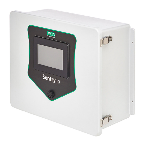
- Page 1 Operating Manual ® SENTRY io Wall Mount Controller Order No.: 10225296/02 Print Spec: 10000005389 (R) CR: 800000061840 MSAsafety.com...
- Page 2 Otherwise, it could fail to perform as designed, and persons who rely on this device could sustain serious injury or death. The warranties made by MSA with respect to the product are voided if the product is not installed and used in accordance with the instructions in this manual.
-
Page 3: Table Of Contents
4.1.1 Setting the System Language 4.1.2 Setting the Date and Time 4.1.3 Setting the Communication Information 4.1.4 Setting the Administration Password Input/Output Configuration Detectors and Alarm Setpoints 4.3.1 Auto Identifying Detectors 4.3.2 Manually Identifying Detectors 4.3.3 Detectors Summary SENTRY io... - Page 4 Software Update Process Technical Specifications Maintenance Periodic Functional Test Calibration Check Cleaning Storage Troubleshooting Ordering Information 10.1 Controller 10.2 Accessories/Spare Parts MSA Permanent Instrument Warranty Resources 12.1 Cause and Effect Planning 12.2 Power Consumption Calculation 12.3 Modbus Address List SENTRY io...
-
Page 5: Safety Regulations
Safety Regulations Read this manual carefully before using the SENTRY io. The SENTRY io will perform as designed only if it is used and maintained in accordance with the manufacturer's instructions. Otherwise, it could fail to perform as designed and persons who rely on the SENTRY io for their safety could sustain serious personal injury or death. -
Page 6: Correct Use
The SENTRY io is designed to accept standard 4-20 mA analog signal inputs from connected MSA or generic gas detectors and will also accept discrete inputs from contact closure devices such as switches or relay contacts. The system provides discrete relay outputs for use in energizing notification devices such as sounders, strobes, or horns. -
Page 7: Overview
2 Overview Overview Components Buckle Analog input terminations SD card, Ethernet ports, USB Digital input terminations Gasket Modules Fan bracket Power supply Hinge Relays PLC / HMI Power Buzzer Analog output SENTRY io... -
Page 8: Control Unit
Power Supply The 24 VDC, 10A power supply accepts main AC power. The SENTRY io uses a COSEL power supply (PN: KHNA240F-24) or equivalent - for specifications, please refer to the COSEL product page. The COSEL KHNA240F-24 complies with SELV requirements as per UL 60950-1 and OSHA Class I Div. 1 requirements. -
Page 9: Cpu And Hmi Touchscreen Panel
2.2.4 Buzzer The SENTRY io buzzer is designed to audibly alert you when an event occurs. The buzzer is not intended to be the primary indicator of an alarm condition. The buzzer has distinct tones for both alarm and fault: Alarm—Steady tone... -
Page 10: Input Devices Compatibility
Analog Inputs The SENTRY io is designed to provide 24 VDC field device power for connected, 2 and 3-wire 4-20 mA signal fixed gas detectors. The wiring termination blocks for connected gas detectors are located in the lower left hand corner of the panel. -
Page 11: Output Devices Compatibility
The wiring termination blocks for discrete input device connections are located to the right of the 4-20 mA signal input terminal blocks and utilize a two-tier terminal block. The SENTRY io enables the internal 24 VDC power to be used for the discrete 24 VDC signal inputs. - Page 12 The SENTRY io comes pre-wired with all contacts dry except for relays 5-8 (which includes the buzzer on relay 5). To add additional powered relays, you need to connect 0 VDC and 24 VDC to the terminal strip as shown below. Powered contacts are used for things like horn and strobe activation.
-
Page 13: Gas Reading Conversion
MSA instrument's instruction manual for the relevant fault code explanation. The Sentry io also shows a general fault if there is an internal error or PLC failure.This fault is shown on the home screen and in the alarm log with a time stamp. -
Page 14: Field Cabling
Cable shielding for all input and output devices must be connected to SENTRY io chassis ground. NOTE: SENTRY io terminal blocks can accept a maximum wire gauge of 12 AWG and a minimum gauge of 18 AWG, one wire per terminal. - Page 15 If selected, user must define Voting Zones required and names of each Zone User must define which Discrete signals and Analog Alarm signals shall be evaluated within Zone voting logic For assistance, use the Cause and Effect Planning spreadsheet in the SENTRY io Online Help to do your cause and effect pre-planning.
-
Page 16: Installation
Packaging materials are removed from inside the SENTRY io CAUTION! Due to the weight of the SENTRY io, unpacking and removing it from the container may require an additional person to assist. Failure to follow this caution can result in minor or moderate injury. -
Page 17: Wire Entry Penetrations
SENTRY io enclosure before doing work inside the enclosure. ESD can cause damage to the SENTRY io. Do not touch the electronic circuit boards. When closing and latching the SENTRY io door, ensure the enclosure door seal is free from debris and the door is tightly sealed. -
Page 18: Electrical Installation Procedure
7. Connect the AC power wiring to the #1 AC terminal block (HOT) and #2 AC terminal block (NEUTRAL) input terminals. Make sure the connectors are seated securely. 8. Connect the AC power ground wire to the ground lug so the SENTRY io chassis ground is connected to the earth ground. - Page 19 When wiring each node, connect the cable shield to the functional ground point of the RS485 terminal block. In order to avoid ground-loops, do not connect the RS485 functional ground terminal to the Earth of the SENTRY io as it is internally connected to the SENTRY io's functional ground point.
-
Page 20: Device Level Ring (Dlr)
Remote Displays SENTRY io has the ability to support a remote display over Ethernet. A remote display will act and function the same way as the primary SENTRY io display. Both the primary and remote displays will have the ability to function simultaneously. -
Page 21: Relay Outputs
A clamping diode in parallel with each inductive DC load. An RC snubber circuit in parallel with each inductive AC load. DC Load AC Load Refer to the Installation Outline drawing (SK3015-1071) for additional details on the relay outputs. SENTRY io... -
Page 22: Configuration
4 Configuration Configuration The first time the SENTRY io is connected to power, the SmartStart configuration wizard displays upon initialization. Before normal operation of the SENTRY io, you must proceed through the steps of the SmartStart configuration wizard. The configuration involves input steps for the following system parameters: 1. -
Page 23: Setting The Communication Information
4. Tap the Password tab to proceed to the Password screen. —or— Tap Next to end the General Settings configuration and proceed to the I/O configuration. NOTE: You cannot go back in the process once you tap Next. SENTRY io... -
Page 24: Setting The Administration Password
4.3.2 Manually Identifying Detectors for more information. NOTE: The SENTRY io EZ-ID process uses preset full-scale instrument ranges, therefore do not rescale the range at instrument. If rescaling is necessary, manual identification may be needed. NOTE: For auto-identified sensors, the SENTRY io uses default mA fault levels for instruments. Therefore the default mA... -
Page 25: Manually Identifying Detectors
If this is necessary, manual identification may be needed. NOTE: For dual sensor configurations on Ultima X5000 and S5000, SENTRY io auto identification will only load information for sensor #1. You can manually add sensor #2. -
Page 26: Alarm Set-Points
4. Select a channel by swiping or using locate the desired channel number. 5. Tap Ok. Once you select the channel, the alarm levels auto populate with default values. SENTRY io... -
Page 27: Digital Inputs
SENTRY io to the MSA detector. If this is not selected, then the SENTRY io and MSA detector can maintain different set-points. 7. If you want to change the alarm level values, they must be changed in order. -
Page 28: Relays
3. If performing fast relay assignment but not performing separate relay assignment, choose whether to perform common relay assignment. 4. Select the desired module tab to view its relays. 5. Tap a relay to edit it. NOTE: Relays with a grey background cannot be edited. SENTRY io... -
Page 29: Voting Zones
Voting Zones The SENTRY io logic programming supports “OR” gate and “AND” gate logic functions in the SmartStart setup wizard. Any OR gates may be selected in zoning logic section, or “2 of N” or “3 of N” are also selectable to achieve limited “AND” gate functions. -
Page 30: Cause And Effect
6. Tap Finish. 7. Tap Press Here to Go Live to complete the SmartStart configuration wizard. —or— Tap Modify Configuration to go back to the Detector Identifications screen and modify any necessary items of the configuration. SENTRY io... -
Page 31: System Verification
5 System Verification System Verification 1. Connect the detector(s) to the SENTRY io. 2. Configure the SENTRY io. 3. Verify detector information on the dashboard. 4. Test the detector alarm setpoints with the application or simulation of gas. 5. Test the buzzer response to alarm state. Verify the volume level of the buzzer is sufficient for the ambient noise level in the environment. -
Page 32: Operation
Operation Dashboard NOTE: On some instruments, CLO2 and CO2 show as two decimal places (x.xx). The SENTRY io is limited to one decimal place (x.x). NOTE: Some Oxygen instruments have a calibration output signal >20mA and may display as "overrange" on the SENTRY io. - Page 33 Alarm 3 to 22. If synchronizing with the SENTRY io, it is best to set alarms to a 2 alarm configuration on the SIO since it will never show the alarm above 22.
-
Page 34: Inhibiting Or Activating Digital Inputs
6.1.2 Inhibiting or Activating Digital Inputs The digital inputs set up in the SENTRY io SmartStart configuration process display across the top of the dashboard. You can inhibit or activate them from the dashboard with admin access. 1. Tap one of the digital input indicators on the dashboard. -
Page 35: Viewing The Alarm Summary
4. Tap CLR to clear, ACK to acknowledge, or ACK & CLR to do both. You can select multiple alarms to perform bulk actions. Tools The SENTRY io Tools screen contains configuration options for the dashboard view, system language, and communication type. 6.2.1 Updating the Dashboard View 1. -
Page 36: Updating The Communication Type
6.3.1 Modifying the Configuration You can return to the SmartStart configuration wizard to modify the configuration without having to reset the SENTRY io. 1. From the dashboard, tap the Settings icon 2. Tap the textbox, enter the administrator password, and tap OK. -
Page 37: Backing Up The Database
The SD Card can be found below the USB Port on the left side of the back of the display module. Push in on the SD card to eject. Software Update Process The SENTRY io software may require updating over time. If you are notified that a new software update is available for your unit, please contact MSA Customer Support. SENTRY io... -
Page 38: Technical Specifications
7 Technical Specifications Technical Specifications Mechanical Specifications SENTRY io size 558.8 mm x 447.68 mm x 241.3 mm SENTRY io weight 20 kg Materials Fiberglass Ratings NEMA-4X, IP65 Operating and storage temperature range -20 °C to 65 °C Humidity 20-90% relative humidity (non-condensing) Atmospheric pressure range 86 kPa –... - Page 39 Certified by FM Approvals for US, Canada (FM22CA0007), ATEX (FM22ATEX0006), IECEx (IECEx FMG 22.0007), UKCA (FM23UKEX0046) Performance certification includes: IEC/EN/UL/FM 60079-29-1, EN 50104, FM 6320, FM6340, ANSI/ISA 92.00.01, ANSI/ISA 92.04.01 EMC Directive, REACH Regulation and RoHS Directive compliant SENTRY io...
-
Page 40: Maintenance
Failure to follow this warning can result in serious personal injury or death. Storage The SENTRY io enclosure should be stored in a clean, dry area that is within the temperature and humidity ranges quoted 7 Technical Specifications. You should insert dust caps into any vacant cable entry holes during storage. -
Page 41: Troubleshooting
Ensure detectors are set in default analog settings NOTE: For X5000 and S5000 sensors, the 0 value is 4.04 mA so the readout at the SENTRY io might be slightly higher than 0 – this is normal operation. Failed to recognize hardware... - Page 42 9 Troubleshooting Condition Corrective Action points, scale, units) On the Setpoints screen in the SmartStart configuration wizard, select Write A1 & A3 alarm set-points to MSA detectors via HART Instrument reading does not match Ensure instrument is properly wired controller reading...
- Page 43 Any fault code shown is derived from HART command 48. See instrument display for more information Can I export trends Copy file from SD card directory <dir> Can I export cause & effect Copy file from SD card directory <dir> SENTRY io...
-
Page 44: Ordering Information
CONTROLLER,SENTRY io,8PT,16RLY,8AO,M20 10211155 CONTROLLER,SENTRY io,8PT,16RLY,8AO,STD 10214614 CONTROLLER,SENTRY io,8PT,32RLY,0AO,M20 10211156 CONTROLLER,SENTRY io,8PT,32RLY,0AO,STD 10214615 CONTROLLER,SENTRY io,8PT,32RLY,8AO,M20 10211157 CONTROLLER,SENTRY io,8PT,32RLY,8AO,STD 10214616 CONTROLLER,SENTRY io,16PT,32RLY,16AO,M20, SILICONE FREE 10223690 10.2 Accessories/Spare Parts Description Part Number ANALOG OUTPUT MODULE,24VDC,6 CHANNEL 10207363 BUZZER 10207360 DISPLAY,24VDC,7",TFT LCD 10207361 EXPANSION MODULE,END,UNITRONICS... - Page 45 10 Ordering Information Description Part Number KIT,PLUG,IP66,¾ KNOCKOUT 10218717 KIT,TERMINAL BLOCK, TWO LEVEL,SENTRY io 10218719 KIT,TERMINAL BLOCK,THREE LEVEL,SENTRY io 10218718 MEMORY CARD, MICRO SD, 16GB 10215755 POWER SUPPLY,24V,10A 10207358 RELAY MODULE,24VDC,8 I/O 10207365 M20 CABLE GLAND KIT 10090929 SENTRY io...
-
Page 46: Msa Permanent Instrument Warranty
MSA the Safety Company warrants that this product will be free from mechanical defect or faulty workmanship for a period of two (2) years from the date of delivery, provided it is maintained and used in accordance with MSA's instructions and/or recommendations. -
Page 47: Resources
The Cause and Effect Planning spreadsheet is provided as a documentation aid to pre-plan the programming of the SENTRY io. The spreadsheet does not validate the programming logic or confirm that the programming is appropriate and sufficient for your application.
Need help?
Do you have a question about the SENTRY io and is the answer not in the manual?
Questions and answers