MSA GasGard XL Operating Manual
Wall mount controller
Hide thumbs
Also See for GasGard XL:
- User instructions (118 pages) ,
- Operating manual (82 pages) ,
- Quick start manuals (2 pages)
Table of Contents
Advertisement
Quick Links
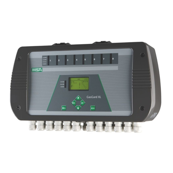
GasGard
Wall Mount Controller
Operating Manual
In North America, to contact your nearest stocking location, dial toll-free 1-800-MSA-INST
To contact MSA International, dial 1-412-967-3354
© MINE SAFETY APPLIANCES COMPANY 2008 - All Rights Reserved
This manual is available on the internet at www.msanet.com
Manufactured by
MSA NORTH AMERICA
P.O. Box 427, Pittsburgh, Pennsylvania 15230
(L) Y Rev 0
®
XL
10091922
Advertisement
Table of Contents

Subscribe to Our Youtube Channel
Related Manuals for MSA GasGard XL


Summary of Contents for MSA GasGard XL
- Page 1 ® Wall Mount Controller Operating Manual In North America, to contact your nearest stocking location, dial toll-free 1-800-MSA-INST To contact MSA International, dial 1-412-967-3354 © MINE SAFETY APPLIANCES COMPANY 2008 - All Rights Reserved This manual is available on the internet at www.msanet.com...
- Page 2 "! WARNING THIS MANUAL MUST BE CAREFULLY READ BY ALL INDIVIDUALS WHO HAVE OR WILL HAVE THE RESPONSIBILITY FOR USING OR SERVICING THE PRODUCT. Like any piece of complex equipment, this instrument will perform as designed only if it is used and serv- iced in accordance with the manufacturer’s instructions.
- Page 3 MSA Permanent Instrument Warranty 1. Warranty- Seller warrants that this product will be free from mechanical defect or faulty workmanship for a period of 18 months from date of shipment, or one year from installation, whichever occurs first, provided it is maintained and used in accordance with Seller's instructions and/or recommendations.
-
Page 4: Table Of Contents
Table of Contents Chapter 1, Product Introduction ....1-1 Correct Use ........1-1 Chapter 2, Description . - Page 5 Chapter 3, Installation ......3-1 Mechanical Installation ......3-2 Electrical Installation .
- Page 6 Sensor List ......A-1 Table A-1.GasGard XL-compatible Sensors ..A-1 Appendix B, Wiring Diagrams .
- Page 7 Appendix C, Individual Relay Connections ...C-1 Figure C-1. Individual Relay Connections ..C-1 Appendix D, Terminal Connectors ....D-1 Figure D-1.
-
Page 8: Product Introduction
Chapter 1, Product Introduction Correct Use The GasGard XL Wall Mount Controller is a compact control unit that: • connects with up to eight active combustible, toxic and/or oxygen sensors • is used to monitor indoor industrial locations for the presence of... -
Page 9: Chapter 2, Description
Chapter 2, Description General Overview The general-purpose control system enables: • Combustible gas monitoring • for protecting operational plants and workers by monitoring atmospheres for potentially explosive gases/vapors in air before they reach the lower explosion limit and by activating alarms and initiating risk aversion measures. -
Page 10: Control Unit
Control Unit Figure 2-1. Enclosure Power Supply Cable entries Channel Relay Board Backup Battery Channel Board Enclosure with mounting holes Sensor Extension Board Wall Mount Enclosure The Control Unit: • is housed in an ABS enclosure in accordance with IP 56 and NEMA 4X •... -
Page 11: Power Supply
Power Supply • The 100 W power supply accepts main AC and DC power. • In case of loss of main power, the power supply automatically switches to backup battery. • Power source for detector is 24 VDC. Backup Battery Two batteries in series (12 VDC/2.2 Ah lead acid) can be used in the Control Unit as an option. -
Page 12: Display Board
• For SCADA visualization software, all three interfaces can be used. • For service access, as a safety precaution, only the two ModBus RTU communications can be used. Standard common outputs are incorporated: • two SPDT (Single Pole Double Throw) relays common alarm (ALARM 1 and ALARM 2) •... -
Page 13: Channel Relay Board
Channel Relay Board Every Channel Relay board: • provides eight output relays • is connected to the Main board or Sensor Extension board (one by one) via connectors. Relays are fully user-configurable from the front panel or connected PC via configuration software. Two optional SPDT (Single Pole Double Throw) relays per channel (eight relays per four channels) are configurable for individual alarms: •... -
Page 14: Front Panel
Front Panel The Front Panel enables communication with the Control Unit and is used to: • monitor the status of all connected field sensors • determine system settings • configure all settings. Figure 2-2. Front Panel Common LEDs Alarm Acknowledgement Alarm Reset Graphic Display Control Push Buttons... -
Page 15: Control Push Buttons
Control Push Buttons Using the control push buttons, the user can operate the menu prompt as shown below. For more information, see Chapter 4. Right button [ ↵ ] Up Button [ Left button [ ESC ] Down button [ Alarm Acknowledgement Alarm Reset Channel Status Info LEDs... - Page 16 1. The green Power LED: Channel is powered and enabled by the system. 2. The yellow Status LED: Channel is in a fault condition. • Blinking LED (0.5 Hz): Channel is disabled. 3. The red Alarm 1 LED: First alarm level is reached. It further indicates the specific status: •...
-
Page 17: Unit Status Info Leds
Unit Status Info LEDs Figure 2-5. Unit Status Info LEDs 1. Green Power LED: Control Unit is powered. • Blinking LED: battery power supply. 2. Yellow Failure LED: Sensor is in fault condition. 3. Yellow System LED: Control Unit has a system fault. -
Page 18: Chapter 3, Installation
Chapter 3, Installation NOTE: Reference shipping documents and carton label to check that delivered components are correct before installation. • The installation location for the Control Unit must be outside the potentially explosive area and free of corrosive gases. • Sensors for use in the potentially explosive area must have the appropriate approval and be installed in accordance with all relevant local and national regulations. -
Page 19: Mechanical Installation
Mechanical Installation Figure 3-1. Mounting Drawing [dimensions in inches (mm)] Mount the Control Unit as follows: 1. Mark holes for the four fixing screws as shown in FIGURE 3-1. 2. Drill four holes of appropriate diameter for the wall plugs. 3. -
Page 20: Power Supply
If an external earth connection is permitted or demanded by the local authorities, it serves merely as additional earthing. • Select an installation location that complies with the environmental conditions indicated in the technical data. • When installing the Control Unit, the following conditions must be met to comply with the European EMC Directive •... -
Page 21: Sensor Connection
Figure 3-2. Connecting the Main Supply Sensor Connection • The sensor must be connected to the terminals on the Main board or Sensor Extension board (See Appendices C and D for details). " CAUTION Follow the instructions for components subject to damage from static electricity!bb •... -
Page 22: Chapter 4, Operation
Chapter 4, Operation The integrated operation/display unit: • is the control system user interface • displays alarms, warnings, and system parameters. • Connecting the operating unit to a PC enables a user-friendly operator interface. • Input fields are set up as selection fields as much as possible, with all known inputs displayed. -
Page 23: Status Info Symbols
• System Date and Time: Actual preset values for events archive (default is DD/MM) • Channel Number: Position of the channel board [counted from left to the right on the Main board (1 … 4) and the Sensor Extension board (5 … 8)]. •... - Page 24 Inhibit: Displays if channel is inhibited STEL Alarm: Displays if STEL alarm is reached TWA Alarm: Displays if TWA alarm is reached Battery included and fully charged Battery included but discharged (Symbol starts blinking if battery cable disconnected) Battery not included •...
-
Page 25: Controls
Controls Located on the front panel are four control push buttons for Control Unit operation and configuration. SYMBOL PRESS BUTTON TO CAUSE UNIT TO: ENTER: enter a lower menu or accept the change change values/options DOWN: advance the cursor to the next position ESCAPE: exit the upper menu or cancel the change ACKNOWLEDGEMENT:... -
Page 26: Using The Hotkeys
Using the Hotkeys Pressing some of the front panel control push buttons for a longer period accesses some additional basic screen features. Pressing button for five seconds changes the language from English to one of 10 local languages and back ESCAPE: Pressing button for five seconds starts the GasGard XL Selftest Process, testing the:... -
Page 27: Viewing Channel Information
Viewing Channel Information 1. Viewing the Basic Screen, press [ENTER]. 2. Select the channel by pressing [DOWN] 3. Press [ENTER] to confirm. The next screen (above) shows channel information as: 1 - Channel number 4 - Measured gas value and unit or channel state 2 - Measured gas 5 - Preset alarm levels 3 - Active Channel Symbol... -
Page 28: Viewing Events Archive
Viewing Events Archive 1. Viewing the Basic Screen, press [ENTER]. 2. Select the Event Archive button by pressing [DOWN] 3. Press [ENTER] to confirm. The next screen (above) shows channel information as: 1 - Event Date 3 - Channel Identification 2 -Event Time 4 - Event Description 4. -
Page 29: List Of Assigned Events
List of Assigned Events Device Turned On 27 Master Calibration Saved Communication OFF 28 New Calibration Saved Communication ON 29 Coil Relay 1 FAULT Board Reset 30 Coil Relay 2 FAULT Alarm1 ON 31 Coil Relay 3 FAULT Alarm1 OFF 32 Coil Relay 4 FAULT Alarm1 Acknowledgement 33 Coil Relay 5 FAULT... -
Page 30: Chapter 5, Configuration
Chapter 5, Configuration All GasGard XL Control Unit parameters can be configured by using: • front panel control push buttons • configuration software tool (see Chapter 6). Two menus allow the user to change unit parameters: (1) System Menu The System menu: •... -
Page 31: System Menu
System Menu The System menu allows full unit configuration: • Modifying channel parameters • Setting output relays (Relays Setting menu) • Calibration (Calibration menu) • General settings (General setting menu). 1. Simultaneously Press [ENTER] and [ESCAPE] and hold for one second. •... -
Page 32: Channel Number
1. Channel Number If selected, the Channel Number allows user to set channel parameters. NOTE: The Channel board Identification Mark must be selected by user to confirm that a channel board is inserted in the slot. 2. Relay Board Identification Mark The Relay board Identification Mark must be selected by the user to confirm that a channel relay board is inserted in the slot: •... -
Page 33: Description Of Channel Parameters
3. Use control push buttons to: - Accept changes and leave menu - Do not accept changes and leave menu - Return to the System menu. Description of Channel Parameters 1. Enter the System menu (see Chapter 5, "System menu"). 2. - Page 34 NOTE: Use [DOWN] to toggle between the two screens. • The second screen displays: Delay: Time delay for alarm activating (0 – 180 seconds); In ATEX version default value is “0”. Hysteresis: Defines Alarm 1 and Alarm 2 hysteresis (from 0 to ±2.0 % full scale). Dead Band: Defines zero baseline (from 0 to ±5.0 % full scale).
-
Page 35: Modifying Channel Parameters
Modifying Channel Parameters 1. Enter into System menu (see Chapter 5, "System Menu"). 2. Use control push buttons to select a channel number to modify and press [ENTER] to confirm. • First of configuration screens appear (left figure). NOTE: Use [DOWN] to toggle between the two screens: 3. -
Page 36: Relay Setting Menu
5. Use the control push buttons to change parameter value. 6. Press [ENTER] to accept the changes. NOTE: Pressing [ESCAPE] toggles to the upper menu. • If FlameGard is selected from the sensor list, the Setting menu changes to the following single screen: 7. -
Page 37: Description Of Relay Parameters
Description of Relay Parameters 1. Enter into the System menu. 2. In the System menu, select the item for “Relay Setting Menu” and press [ENTER] to confirm (see Chapter 5, "System Menu"). Right (ENTER) button [ ↵ ] Up Button [ Left button [ ESC ] Down button [ •... - Page 38 (3) Relays Voting (V): Allows user to set the voting of the selected relays (4) Relay Number (R01-R16): 1 - 8 (Channel Relay board No. 1) 9 - 16 (Channel Relay board No. 2) (5) ATEX Status: Defines the selected relay is related to the channel being configured according to ATEX regulation.
-
Page 39: Example Of Relay Configuration
Example of Relay Configuration Relay HORN no. 1: • is configured as normally de-energized (ND). • is not activated if power is OFF or battery is depleted • is voted if four out of five conditions are met and • is energized if at least four of these conditions are met: •... -
Page 40: Fixed Setting For Common Relays
3. Use control push buttons to select and change required parameter. Right (ENTER) button [ ↵ ] Up Button [ Left button [ ESC ] Down button [ 4. Press [ENTER] to accept the parameter changes. NOTE: Pressing [ESCAPE] returns unit to the upper menu. 5. -
Page 41: General Setting Menu
General Setting Menu The General Setting menu allows the user to: • configure access passwords for the system and Calibration menu • set parameters. 1. Enter the System menu (see Chapter 5, "System Menu"). 2. Use the control push buttons to select "General Setting Menu"; press [ENTER] to confirm. - Page 42 1 - Modbus RTU: Defines the RS 485 / USB communication parameters ADR – unit address Speed – communication speed Parity – setting the parity (Even/Odd) 2 - Modbus TCP / IP: Defines the Ethernet communications parameters ADR – unit IP address MASK - subnetwork mask GATE -...
- Page 43 • For oxygen, if cal enable is ON, the 21 mA signal causes the GasGard XL to go into an overrange status. As soon as the signal drops below 20.4 mA, the user must clear this state by pressing the RESET button.
-
Page 44: Configuration Software
Chapter 6, Configuration Software Installation and Start up For software installation, copy the [GASGARD XL] folder from the installation disc into the user’s own directory. NOTE: To run this software, Java module must be installed on the user’s computer. To launch the application, run the file "run.bat" from the user’s directory. -
Page 45: Application
Application Figure 6-1. Main Applications Screen The main Application screen contains four basic parts: 1 - Menu Bar 3 - Main Screen 2 - Toolbar 4 - Status Bar Menu Bar The menu bar has four pull down menus for application functions: •... -
Page 46: Multilingual System
The window also shows firmware version information. Help The Help menu assists the operator in using the application. Multilingual System The Configuration software is multilingual; for individual languages, use the "lang.properties" configuration file. For additional local language configuration software, contact MSA or an MSA representative. -
Page 47: Setting Up Channels
The window displays the status of all eight channels and allows configuration. UPLOAD button: Allows user to upload configuration from the GasGard XL unit DOWNLOAD button: Allows user to download configuration to the GasGard XL unit OPEN Button: Opens the GasGard XL configuration saved on the hard drive... -
Page 48: Setting Up Output Relays
Setting Up Output Relays From the View menu, user can select the [OUTPUTS] option. Figure 6-3. Setting up Output Relays The window shows the outputs for the connected devices. For each channel and each output relay, the user can select: •... -
Page 49: Chapter 7, Maintenance
Sensor Extension Board (for channels 5 - 8) 10081676 Channel Relay Board 10081677 Channel Board 4 - 20 mA 10081674 GasGard XL, manual 10091922 EMC Filter (to be used with external. 24 VDC supply) 10081680 Back-up battery (2.2 Ah Kit) 10089924... -
Page 50: Technical Specifications And Certifications
515 x 277 x 129 mm (20 x 11 x 5 inches) Weight 5 kg (7 kg with battery) [11 lbs. (15 lbs. with battery)] Pollution Degree Altitude 2000 m (6561 ft) Installation Category The GasGard XL Controller is for indoor use only. -
Page 51: Approvals
Approvals cCSAus Certification Mark Ordinary Location to UL/CSA 61010-1 with performance to the controller portions of CSA 22.2 No. 152 and ISA 12.13 standards. -
Page 52: Appendix A, Sensor List
Appendix A, Sensor List Table A-1.GasGard XL-compatible Sensors 4 – 20 mA TRANSMITTERS FlameGard SafEye Standard 4-20 mA transmitter ULTIMA X (2-wire) ULTIMA X (3-wire) ULTIMA X IR... -
Page 53: Appendix B, Wiring Diagrams
Appendix B, Wiring Diagrams Figure B-1. Flamegard ® Flame Detector Figure B-2. SafEye ® Open Path Gas Detector... - Page 54 Figure B-3. Ultima ® X (Two-wire) Figure B-4. Ultima X ® (Three-wire)
- Page 55 Figure B-5. Ultima ® X IR Sensor...
- Page 56 Appendix C, Individual Relay Connections Figure C-1. Individual Relay Connections...
- Page 57 Appendix D, Terminal Connectors Figure D-1. Main Board Figure D-2. Sensor Extension Board...
- Page 58 Figure D-3. Channel Relay Board...
Need help?
Do you have a question about the GasGard XL and is the answer not in the manual?
Questions and answers