Table of Contents
Advertisement
Quick Links
Advertisement
Table of Contents

Related Manuals for Gefen EXT-DP-CAT7


Summary of Contents for Gefen EXT-DP-CAT7
- Page 1 ® DisplayPort Extender over CAT-7 EXT-DP-CAT7 User Manual www.gefen.com...
- Page 3 ASKING FOR ASSISTANCE Technical Support: Telephone (818) 772-9100 (800) 545-6900 Fax (818) 772-9120 Technical Support Hours: 8:00 AM to 5:00 PM Monday through Friday, Pacific Time Write To: Gefen, LLC. c/o Customer Service 20600 Nordhoff St Chatsworth, CA 91311 www.gefen.com support@gefen.com Notice Gefen, LLC reserves the right to make changes in the hardware, packaging, and any accompanying documentation without prior written notice. DisplayPort Extender over CAT-7 is a trademark of Gefen, LLC © 2013 Gefen, LLC. All rights reserved. All trademarks are the property of their respective owners. Rev A2...
-
Page 4: Table Of Contents
CONTENTS INTRODUCTION........................1 Operating Notes......................2 Features..........................3 Package Includes......................3 Sender Unit Layout......................4 Sender Unit Descriptions....................5 Receiver Unit Layout.......................6 Receiver Unit Descriptions....................7 CONNECTING THE DISPLAYPORT EXTENDER OVER CAT-7...........8 Connections........................8 Wiring Diagram.......................8 OPERATING THE DISPLAYPORT EXTENDER OVER CAT-7..........9 LED Indicators........................9 DIP Switch Configuration....................10 HPD Button........................11 Adjusting the Signal Quality..................12 CABLE TERMINATION......................13 SURFACE MOUNTING INSTRUCTIONS................14 SPECIFICATIONS........................15 WARRANTY..........................16... -
Page 5: Introduction
INTRODUCTION Congratulations on your purchase of the DisplayPort Extender over CAT-7. Your complete satisfaction is very important to us. About Gefen We specialize in total integration for your home theater, while also focusing on going above and beyond customer expectations to ensure you get the most from your hardware. We invite you to explore our distinct product line. Please visit http://www.gefen.com for the latest offerings in High-Definition signal solutions or call us between the hours of 8:00 am and 5:00 pm Monday-Friday, Pacific Standard Time for assistance with your A/V needs. We’ll be happy to assist you. The Gefen DisplayPort Extender over CAT-7 The DisplayPort Extender over CAT-7 allows the installation of a HDTV display up to 100 feet (30 meters) away from a DisplayPort source using two CAT-7 cables. Resolutions up to 1920 x 1200 (WUXGA) or 1080p Full HD when using a single CAT-7 cable, and up to 2560 x 1600 (WQXGA) when using two cables, can be supported. The Receiver unit is powered by the first CAT-7 cable that extends the DisplayPort signal from the Sender unit, eliminating the need for an external power supply on the Receiver unit. How It Works Connect the Sender unit to the DisplayPort source using the included DisplayPort cable. Connect the Receiver unit to the HDTV display using another DisplayPort cable. Connect the Sender unit to the Receiver unit using one or two CAT-7 cables, depending on the maximum required video resolution. Connect the included locking power supply to the Sender unit and an available electric outlet. The Receiver unit is powered by the Link 1 CAT-7 cable and does not require an external power supply. Turn on the power to the source and the display. -
Page 6: Operating Notes
INTRODUCTION READ THESE NOTES BEFORE INSTALLING OR OPERATING THE DISPLAYPORT EXTENDER OVER CAT-7 • CAT-7 cables should not exceed 100 feet (30 meters). • Resolutions up to 1920 x 1200 (WUXGA) or 1080p Full HD are supported when using a single CAT-7 cable. Two CAT-7 cables must be used to support 2560 x 1600 (WQXGA). -
Page 7: Features
INTRODUCTION Features • Extends DisplayPort up to 100 feet (30 meters) • Supports resolutions up to 2560 x 1600 over two CAT-7 cables, and up to 1920 x 1200 or 1080p Full HD over one CAT-7 cable • Supports DisplayPort 1.1a • 16-position EQ rotary switch to compensate for cable skew • HPD Auto-Calibration button • Pre-emphasis switch • Drive level switch • Boost level switches • Power On and Link indicators • Locking power supply • Surface-mountable Package Includes • (1) DisplayPort Extender over CAT-7 (Sender unit) • (1) DisplayPort Extender over CAT-7 (Receiver unit) • (1) 6 ft. DisplayPort cable (M-M) • (1) 5V DC power supply • (1) Quick Start Guide... -
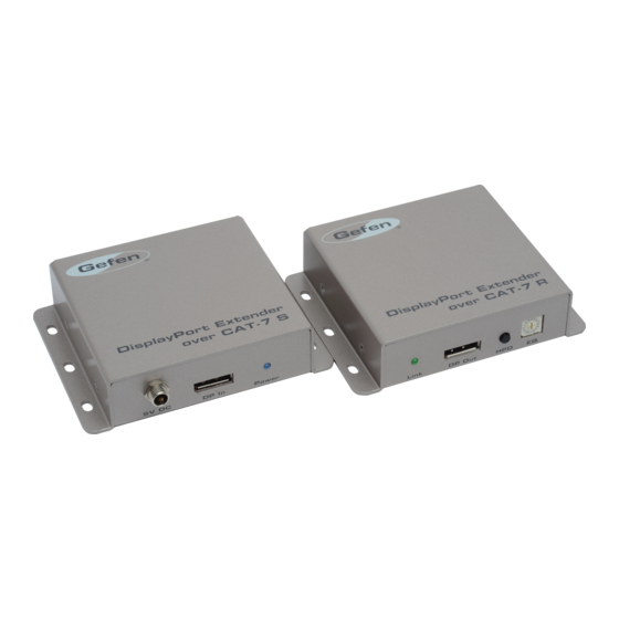
Page 8: Sender Unit Layout
INTRODUCTION Sender Unit Layout Back Front... -
Page 9: Sender Unit Descriptions
INTRODUCTION Sender Unit Descriptions 5V DC Connect the included 5V DC locking power supply to this connector and plug the AC power cord into an available electrical outlet. Only use the power supply shipped with this unit. DP In Connect a Hi-Def source to this port using a DisplayPort cable. Power This LED indicator will glow bright blue when the unit is powered. Link 1 Connect a CAT-7 cable up to 100 feet (30 meters) from this jack to the Link 1 jack on the Receiver unit. Link 2 Connect a CAT-7 cable up to 100 feet (30 meters) from this jack to the Link 2 jack on the Receiver unit. -
Page 10: Receiver Unit Layout
INTRODUCTION Receiver Unit Layout Back Front... -
Page 11: Receiver Unit Descriptions
INTRODUCTION Receiver Unit Descriptions Link This LED indicator will glow bright green when the Sender and Receiver unit are connected using two CAT-7 cables. The Sender unit must be powered. DP Out Connect a DisplayPort cable from this port to the display. HPD Press this button to cycle the HPD line on the Receiver unit. Use this EQ rotary switch to adjust the quality of the output signal, based on the length and type of CAT-7 cable that is being used. See page 12 for more information. Link 1 Connect a CAT-7 cable up to 100 feet (30 meters) from this jack to the Link 1 jack on the Receiver unit. Link 2 Connect a CAT-7 cable up to 100 feet (30 meters) from this jack to the Link 2 jack on the Receiver unit. -
Page 12: Connecting The Displayport Extender Over Cat-7
CONNECTING THE DISPLAYPORT EXTENDER OVER CAT-7 Connections Use the included DisplayPort cable to connect the DisplayPort source to the DP In port on the Sender unit. Connect the display to the Receiver unit using a DisplayPort cable. Connect two CAT-7 cables between the Sender and Receiver units. Each connector on the Sender and Receiver unit is identified as Link 1 and Link 2. When connecting the CAT-7 cables, make sure that each CAT-7 cable that is connected to the Sender unit is connected to the corresponding jack on Receiver unit (e.g. Link 1 --> Link 1, Link 2 --> Link 2). NOTE: The DisplayPort Extender over CAT-7 will support resolutions up to 1920 x 1200 (WUXGA) and 1080p Full HD if only a single CAT-7 cable is used. Two CAT-7 cables must be used to support resolutions up to 2560 x 1600. If only a single CAT-7 cable will be used, the CAT-7 cable must be connected between the Link 1 connectors on both the Sender and Receiver unit. This same CAT-7 cable is used to power the Receiver unit. Connect the included 5V DC locking power supply to the Sender unit. Do not overtighten the locking connectors. Plug the AC power cord from the power supply to an available electrical outlet. Wiring Diagram CAT-7 CABLE DISPLAYPORT CABLE Computer Receiver Sender DisplayPort Display EXT-DP-2CAT7... -
Page 13: Operating The Displayport Extender Over Cat-7
OPERATING THE DISPLAYPORT EXTENDER OVER CAT-7 LED Indicators The LED indicators on the Sender and Receiver unit provide basic information on the current status of the DisplayPort Extender over CAT-7. Status Condition Power Solid blue • Power connected to the Sender unit. • No power supplied to the Sender unit. Link Solid green • DisplayPort Extender over CAT-7 is operating correctly. Solid red • No DisplayPort source connected or source not active. • Receiver unit not connected to display. Flashing red • Receiver is attempting to establish a link with the Sender unit. Power LED Sender unit Link LED Receiver unit... -
Page 14: Dip Switch Configuration
OPERATING THE DISPLAYPORT EXTENDER OVER CAT-7 DIP Switch Configuration The DisplayPort Extender over CAT-7 contains four DIP switches on the bottom of the Sender unit. Adjust the DIP switch settings based on the type and cable length that is being used. Sender unit DIP switches located on the bottom of the Sender Unit. DIP Switch 1 - Differential Output Voltage Select DIP Switch Position Output Voltage ON (default) 1.2 Vpp CENTER 1.0 Vpp 600 mVpp... -
Page 15: Hpd Button
OPERATING THE DISPLAYPORT EXTENDER OVER CAT-7 DIP Switch 2 - Pre-Emphasis Select (Default = OFF) DIP Switch Position Pre-Emphasis 9 dB CENTER 6 dB OFF (default) 0 dB DIP Switch 3 and 4 - Boost Level for Main Link of Sender DIP switch 3 DIP switch 4 Boost Level (dB) @ 5 GHz (default = CENTER) (default = OFF) 2.7 to 7.3 12.2 to 16.6 20.6 to 24.8 27.6 to 28.9 HPD Button The DisplayPort Extender over CAT-7 has an HPD button on the front of the Receiver unit. Pressing this button will cycle the HPD (Hot-Plug Detect) line on the display (sink) device. This HPD button provides the same effect as disconnecting then reconnecting the DisplayPort cable from the Receiver unit. Cycling the HPD line will cause the Receiver unit to re-read the EDID of the display and send it back to the DisplayPort source. HPD button Receiver unit... -
Page 16: Adjusting The Signal Quality
OPERATING THE DISPLAYPORT EXTENDER OVER CAT-7 Adjusting the Signal Quality The DisplayPort Extender over CAT-7 has an equalization device on the front of the Receiver unit. This 16-position rotary switch is used to adjust the boost level depending upon the length of the CAT-7 cable. Insert a small flat-headed tool into the notch on the rotary switch. Rotary switch Receiver unit Turn the rotary switch clockwise or counterclockwise until it clicks to the next position. Check the image. Continue adjusting the rotary switch if the issue is not resolved. -
Page 17: Cable Termination
CABLE TERMINATION Gefen has specifically engineered products to work with the TIA/EIA-568B specification. Please follow the table below when field terminating cable for use with Gefen products. Failure to do so may produce unexpected results and reduced performance. TIA/EIA-568B Termination Color Orange / White Orange Green / White Blue Blue / White Green Brown / White Brown 1 2 3 4 5 6 7 8 Each cable run must consist of a single undivided segment of CAT-7 cabling from the Sender unit to the Receiver unit. Punch-down blocks or splices will not work. -
Page 18: Surface Mounting Instructions
SURFACE MOUNTING INSTRUCTIONS The Gefen DisplayPort Extender over CAT-7 can be mounted on any horizontal or vertical flat surface (e.g. wall or inside / outside a cabinet with wood / drywall screws) as shown in the diagram above. There should be an inch or two of clearance between the edges of the unit and any walls or vertical surfaces to allow for enough clearance for connection and disconnection of the DisplayPort cable. For installation on a drywall surface, use a #6 drywall screw. When installing, it is recommended to use the center hole on a stud. -
Page 19: Specifications
SPECIFICATIONS Video Data Rate....................up to 2.7 Gbps Video Output Voltage....................1.2V p-p Video Input Connector (Sender)..........(1) DisplayPort, 20-pin, female Video Output Connector (Receiver)........(1) DisplayPort, 20-pin, female Link Connectors (Sender/Receiver)............(2) RJ-45, shielded EQ Switch (Receiver)..............(1) 16-position rotary type HPD Auto Calibration button (Receiver)............... (1) tact-type Pre-emphasis switch (Sender)............(1) 3-position DIP switch Drive level switch (Sender)............... (1) 3-position DIP switch Boost level switch (Sender).............. (2) 3-position DIP switch Power On indicator (Sender)................(1) LED, blue Link indicator (Receiver)..........(1) LED, green: good link, red: no link Power Supply connector (Sender)............(1) 5V DC, locking type Operating Temperature............... +32 to +104 °F (0 to +40 °C) Dimensions (W x H x D) (Sender/Receiver)... 4.3” x 1” x 3.3” (110mm x 25mm x 83mm) Shipping Weight....................2.2 lbs (1 kg) -
Page 20: Warranty
This warranty is in lieu of all other warranties expressed or implied, including without limitation, any implied warranty or merchantability or fitness for any particular purpose, all of which are expressly disclaimed. Proof of sale may be required in order to claim warranty. Customers outside the US are responsible for shipping charges to and from Gefen. Copper cables are limited to a 30 day warranty and cables must be in their original condition. The information in this manual has been carefully checked and is believed to be accurate. However, Gefen assumes no responsibility for any inaccuracies that may be contained in this manual. In no event will Gefen be liable for direct, indirect, special, incidental, or consequential damages resulting from any defect or omission in this manual, even if advised of the possibility of such damages. The technical information contained herein regarding the features and specifications is subject to change without notice. For the latest warranty coverage information, refer to the Warranty and Return Policy under the Support section of the Gefen Web site at www.gefen.com. PRODUCT REGISTRATION Please register your product online by visiting the Register Product page under the Support section of the Gefen Web site. - Page 24 Rev A2 20600 Nordhoff St., Chatsworth CA 91311 1-800-545-6900 818-772-9100 fax: 818-772-9120 www.gefen.com support@gefen.com This product uses UL or CE listed power supplies.
Need help?
Do you have a question about the EXT-DP-CAT7 and is the answer not in the manual?
Questions and answers