Table of Contents
Advertisement
Quick Links
Advertisement
Table of Contents

Subscribe to Our Youtube Channel
Related Manuals for Extech Instruments 411


Summary of Contents for Extech Instruments 411
- Page 1 User's Guide True RMS Multimeter Extech 411...
- Page 2 Introduction Congratulations on your purchase of the Extech 411 (part number EX411) True RMS Multimeter. This meter measures AC/DC Voltage, AC/DC Current, Resistance, Diode Test, and Continuity plus Thermocouple Temperature. Proper use and care of this meter will provide many years of reliable service.
-
Page 3: Overvoltage Category
OVERVOLTAGE CATEGORY III This meter meets the IEC 610-1-95 standard for OVERVOLTAGE CATEGORY III. Cat III meters are protected against overvoltage transients in fixed installation at the distribution level. Examples include switches in the fixed installation and some equipment for industrial use with permanent connection to the fixed installation. -
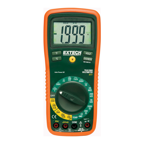
Page 4: Controls And Jacks
Controls and Jacks 1. Rubber holster 2. 2000 count LCD display 3. Degrees F button 4. Degrees C button 5. Function switch 6. mA, uA and A input jacks 7. COM input jack 8. Positive input jack 9. Battery check button 10. -
Page 5: Specifications
Specifications Function Range Resolution Accuracy ±(0.3% reading + 2 digits) DC Voltage 200mV 0.1mV (V DC) 0.001V ±(0.5% reading + 2 digits) 200V 0.1V ±(0.8% reading + 2 digits) 1000V AC Voltage 50 to 400Hz 400Hz to 1kHz (V AC) ±(1.0% reading ±(2.0% reading 0.001V... - Page 6 Specifications Test current of 1mA maximum, open Diode Test circuit voltage 2.8V DC typical Audible signal will sound if the Continuity Check resistance is less than approximately 150Ω 10MΩ Input Impedance True rms AC Response 50Hz to 1kHz ACV Bandwidth 200mV DCA voltage drop 3 ½...
-
Page 7: Dc Voltage Measurements
Operating Instructions WARNING: Risk of electrocution. High-voltage circuits, both AC and DC, are very dangerous and should be measured with great care. 1. ALWAYS turn the function switch to the OFF position when the meter is not in use. 2. If “1 ” appears in the display during a measurement, the value exceeds the range you have selected. -
Page 8: Ac Voltage Measurements
AC VOLTAGE MEASUREMENTS WARNING: Risk of Electrocution. The probe tips may not be long enough to contact the live parts inside some 240V outlets for appliances because the contacts are recessed deep in the outlets. As a result, the reading may show 0 volts when the outlet actually has voltage on it. -
Page 9: Dc Current Measurements
DC CURRENT MEASUREMENTS CAUTION: Do not make current measurements on the 20A scale for longer than 30 seconds. Exceeding 30 seconds may cause damage to the meter and/or the test leads. 1. Insert the black test lead banana plug into the negative COM jack. -
Page 10: Ac Current Measurements
AC CURRENT MEASUREMENTS CAUTION: Do not make current measurements on the 20A scale for longer than 30 seconds. Exceeding 30 seconds may cause damage to the meter and/or the test leads. 1. Insert the black test lead banana plug into the negative COM jack. -
Page 11: Resistance Measurements
RESISTANCE MEASUREMENTS WARNING: To avoid electric shock, disconnect power to the unit under test and discharge all capacitors before taking any resistance measurements. Remove the battery and unplug the line cords. 1. Set the function switch to the highest Ω position. 2. -
Page 12: Continuity Check
CONTINUITY CHECK WARNING: To avoid electric shock, never measure continuity on circuits or wires that have voltage on them. 1. Set the function switch to the position. 2. Insert the black lead banana plug into the negative COM jack. Insert the red test lead banana plug into the positive Ω... -
Page 13: Temperature Measurements
TEMPERATURE MEASUREMENTS 1. Set the function switch to the TEMP position. 2. Insert the Temperature Probe into the Temperature Socket, making sure to observe the correct polarity. 3. Press the ºF or ºC button for the desired units. 4. Touch the Temperature Probe head to the part whose temperature you wish to measure. - Page 14 DISPLAY BACKLIGHT Press and hold the button to turn on the display backlight function. The backlight will automatically turn off after 15 seconds. BATTERY CHECK CHECK function tests the condition of the 9V battery. Set the function switch to the 200VDC range and press the CHECK button.
-
Page 15: Maintenance
Maintenance WARNING: To avoid electric shock, disconnect the test leads from any source of voltage before removing the back cover or the battery cover. WARNING: To avoid electric shock, do not operate your meter until the battery and fuse covers are in place and fastened securely. -
Page 16: Replacing The Battery
REPLACING THE BATTERY WARNING: To avoid electric shock, disconnect the test leads from any source of voltage before removing the battery cover. 1. When the battery becomes exhausted or drops below the operating voltage, The symbol will appear in the LCD display when the battery check button is pressed. -
Page 17: Replacing The Fuses
REPLACING THE FUSES WARNING: To avoid electric shock, disconnect the test leads from any source of voltage before removing the fuse cover. 1. Disconnect the test leads from the meter. 2. Remove the protective rubber holster. 3. Remove the battery cover (two “B” screws) and the battery. 4. -
Page 18: Warranty
Warranty EXTECH INSTRUMENTS CORPORATION warrants this instrument to be free of defects in parts and workmanship for one year from date of shipment (a six month limited warranty applies on sensors and cables). If it should become necessary to return the instrument for service during or beyond the warranty period, contact the Customer Service Department at (781) 890-7440 ext.
Need help?
Do you have a question about the 411 and is the answer not in the manual?
Questions and answers