Advertisement
Table of Contents
Advertisement
Table of Contents

Subscribe to Our Youtube Channel
Related Manuals for Extech Instruments MN35


Summary of Contents for Extech Instruments MN35
- Page 1 USER MANUAL MiniTec Series Manual Ranging Mini MultiMeter Model MN35 ...
-
Page 2: International Safety Symbols
Double insulation Safety Precautions 1. Improper use of this meter can cause damage, shock, injury or death. Read and understand this user manual before operating the meter. 2. Make sure any covers or battery doors are properly closed and ured. 3. Always remove the test leads before replacing the battery or fuses. 4. Inspect the condition of the test leads and the meter itself for any damage before operating the meter. Repair any damage before use. 5. Do not exceed the maximum rated input limits. 6. Use great care when making measurements if the voltages are greater than 25VAC rms or 35VDC. These voltages are considered a shock hazard. 7. Always discharge capacitors and remove power from the device under test before performing Diode, Resistance or Continuity tests. 8. Remove the battery from the meter if the meter is to be stored for long periods. 9. To avoid electric shock, do not measure AC current of any kind Input Limits Function Maximum Input VDC, VAC 600V DC/AC Resistance, Diode, Continuity 500V DC/AC mA DC 250mA DC 10A DC 10A DC (15sec. max every 15 min.) MN35-EU-EN V2.3 4/13... -
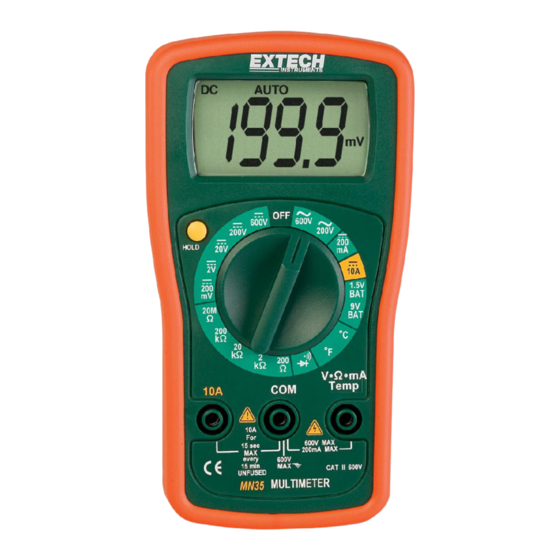
Page 3: Meter Description
access is on the rear of unit. Operating Instructions Note: If “H” and a blank screen appear when the meter is turned on the HOLD feature is active. Press the HOLD button to exit the HOLD mode. AC or DC Voltage Measurements 1. Insert the black test lead banana plug into the negative COM jack and the red test lead banana plug into the positive V jack. 2. Turn the rotary switch to the highest VAC or VDC position. 3. Touch the test probes to the circuit under test and read the voltage on the display. 4. Reset the function switch to successively lower positions to obtain a higher resolution reading. If the polarity is reversed (DC voltage only), the display will show (‐) minus before the value. DC Current Measurements CAUTION: Do not make current measurements on the 10A scale for longer than 15 seconds followed by a 15 minute cool down period. Exceeding 15 seconds may cause damage to the meter and/or the test leads. 1. Insert the black test lead banana plug into the negative COM jack. 2. For current measurements up to 200mA DC, set the function switch to the 200mA DC position and insert the red test lead banana plug into the V//mA jack. 3. For current measurements up to 10A DC, set the function switch to the 10A DC range and insert the red test lead banana plug into the 10A jack. 4. Remove power from the circuit under test, then open up the circuit at the point where you wish to measure current. 5. Touch the black test probe tip to the negative side of the circuit. Touch the red test probe tip to the positive side of the circuit. 6. Apply power to the circuit. 7. Read the current in the display. MN35-EU-EN V2.3 4/13... -
Page 4: Resistance Measurements
Diode Measurements 1. Insert the black test lead banana plug into the negative COM jack and the red test lead banana plug into the positive V//mA jack. 2. Turn the rotary switch to the •))) position. 3. Touch the test probes to the diode under test. Forward voltage will indicate 0.4V to 0.7V. Reverse voltage will indicate “1. ”. Shorted devices will indicate near 0mV and an open device will indicate “1. ” in both polarities. Battery Test 1. Insert the black test lead banana plug into the negative COM jack and the red test lead banana plug into the positive V jack. 2. Turn the rotary switch to the 1.5V or 9V BAT position. 3. Connect the red test lead to the positive side of the 1.5V or 9V battery and the black test lead to the negative side of the 1.5V or 9V battery. 4. Read the voltage in the display. Good Weak Bad 9V battery: >8.2V 7.2 to 8.2V <7.2V 1.5V battery: >1.35V 1.22 to 1.35V <1.22V Data Hold Press the Hold button to freeze the reading in the display. “H” will appear in the LCD. Press the key again to release the display. MN35-EU-EN V2.3 4/13... -
Page 5: Maintenance
Maintenance WARNING: To avoid electric shock, disconnect the test leads from any source of voltage before removing the battery/fuse cover. WARNING: To avoid electric shock, do not operate your meter until the battery/fuse cover is in place and fastened securely. This Multimeter is designed to provide years of dependable service, if the following care instructions are performed. Keep the meter dry. Use and store the meter in mild ambient conditions. Temperature extremes can shorten the life of the electronic parts and distort or melt plastic parts. Handle the meter gently. Dropping it can damage the electronic parts or the case. Keep the meter clean. Wipe the case occasionally with a damp cloth. DO NOT use chemicals, cleaning solvents or detergents. Use only fresh batteries of the recommended size and type. Remove old or weak batteries so they do not leak and damage the unit. If the meter is to be stored for a long period of time, the batteries should be removed to prevent damage to the unit. MN35-EU-EN V2.3 4/13... -
Page 6: Battery Replacement
2. Remove the rubber holster (if in place). 3. Remove the two screws securing the rear cover using a Phillips head screwdriver. 4. Lift the cover off and replace the battery observing the correct polarity. 5. Insert the new battery into the battery holder. 6. Replace the rear cover and secure with the screws. Never dispose of used batteries or rechargeable batteries in household waste. As consumers, users are legally required to take used batteries to appropriate collection sites, the retail store where the batteries were purchased, or wherever batteries are sold. Disposal: Do not dispose of this instrument in household waste. The user is obligated to take end‐of‐life devices to a designated collection point for the disposal of electrical and electronic equipment. Other Battery Safety Reminders o Never dispose of batteries in a fire. Batteries may explode or leak. o Never mix battery types. Always install new batteries of the same type. Fuse Replacement WARNING: To avoid electric shock, disconnect the test leads from any source of voltage before removing battery/fuse cover. Disconnect the test leads from any circuit being measured. Remove the rubber holster (if in place). Remove the two screws securing the rear cover using a Phillips head screwdriver. Remove the rear cover. Remove the old fuse by gently pulling up on it. Install the new fuse by gently pushing it into the holder. Always use a fuse of the proper size and value; 250mA/250V fast blow. Replace the rear cover and secure with the screws. MN35-EU-EN V2.3 4/13... -
Page 7: Specifications
C 5 C (73 F) and less than 70% RH Diode Test Test current of 1mA maximum, open circuit voltage 2.8V DC typical Continuity Check Audible signal will sound if the resistance is less than approximately <40 5 Temperature sensor Requires type K thermocouple Input Impedance 10M (VDC) and 4.5M (VAC) Display 1999 count LCD Overrange “1 or ‐1” is displayed Polarity Automatic (no indication for positive polarity); Minus (‐) sign for negative polarity. Measurement Rate3 times per second, nominal Low Battery “ ” is displayed if battery voltage drops below operating voltage Batteries Requires one 9V battery (NEDA 1604 or equivalent) Fuses mA range; 250mA/250V fast blow 10A range, no protection Operating Temp 0 C to 40 C (32 F to 104 F) Storage Temp ‐20 C to 60 C (‐4 F to 140 F) MN35-EU-EN V2.3 4/13... - Page 8 AC (voltage) DC (direct current or voltage) •))) Continuity and Diode test mV, V millivolt, volt (voltage) k M ohm, kilohm, megohm (resistance) µA, mA, A microamp, milliamp, Amp (current) º º F, C Degrees Fahrenheit, centigrade (temperature) º Low battery HOLD Display hold Copyright © 2013 FLIR Systems, Inc. All rights reserved including the right of reproduction in whole or in part in any form ISO‐9001 Certified www.extech.com . MN35-EU-EN V2.3 4/13...
Need help?
Do you have a question about the MN35 and is the answer not in the manual?
Questions and answers