Table of Contents
Advertisement
Quick Links
Download this manual
See also:
Operating Manual
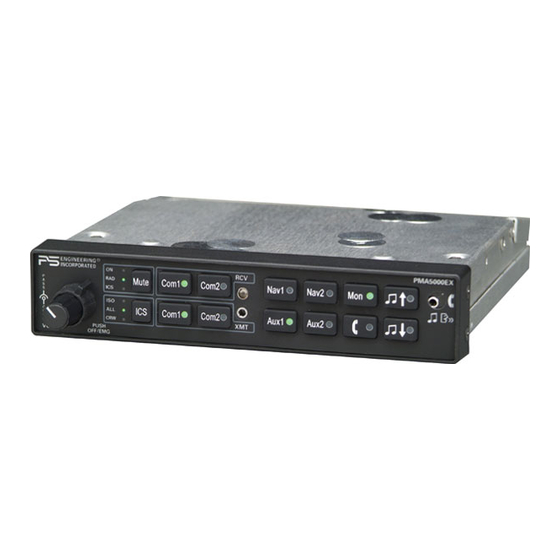
Audio Selector Panel with 4-Place IntelliVox® Stereo Intercom
Audio Selector Panel with 4-Place IntelliVox® Stereo Intercom
Audio Selector Panel with 4-Place IntelliVox® Stereo Intercom
Patented under one or more of the following;
Patented under one or more of the following;
Patented under one or more of the following;
No. 4,941,187; 5,903,227; 6,160,496 and 6,493,450
No. 4,941,187; 5,903,227; 6,160,496 and 6,493,450
No. 4,941,187; 5,903,227; 6,160,496 and 6,493,450
For use in Experimental/Non-certified aircraft ONLY
For use in Experimental/Non-certified aircraft ONLY
For use in Experimental/Non-certified aircraft ONLY
The product warranty is not valid unless this product is installed by an
The product warranty is not valid unless this product is installed by an
The product warranty is not valid unless this product is installed by an
Any reproduction or retransmittal of this publication, or any portion thereof, without the expressed written permission of PS
Any reproduction or retransmittal of this publication, or any portion thereof, without the expressed written permission of PS
Any reproduction or retransmittal of this publication, or any portion thereof, without the expressed written permission of PS
Engineering, Inc. is strictly prohibited. For further information contact the Publications Manager at PS Engineering, Inc., 9800
Engineering, Inc. is strictly prohibited. For further information contact the Publications Manager at PS Engineering, Inc., 9800
Engineering, Inc. is strictly prohibited. For further information contact the Publications Manager at PS Engineering, Inc., 9800
Martel Road, Lenoir City, TN 37772. Phone (865) 988-9800, email contact@ps-engineering.com.
Martel Road, Lenoir City, TN 37772. Phone (865) 988-9800, email contact@ps-engineering.com.
Martel Road, Lenoir City, TN 37772. Phone (865) 988-9800, email contact@ps-engineering.com.
9800 Martel Road
9800 Martel Road
9800 Martel Road
Lenoir City, TN 37772
Lenoir City, TN 37772
Lenoir City, TN 37772
www.ps-engineering.com
www.ps-engineering.com
www.ps-engineering.com
P
P
P
M
M
M
A
A
A
P
P
P
M
M
M
A
A
A
Document P/N 200-550-0100
Document P/N 200-550-0100
Document P/N 200-550-0100
Rev. 3, December 2015
Rev. 3, December 2015
Rev. 3, December 2015
System Installation and Operation Manual
System Installation and Operation Manual
System Installation and Operation Manual
Not intended for installation in certified aircraft
Not intended for installation in certified aircraft
Not intended for installation in certified aircraft
Authorized PS Engineering dealer.
Authorized PS Engineering dealer.
Authorized PS Engineering dealer.
PS Engineering, Inc. 2015 ©
PS Engineering, Inc. 2015 ©
PS Engineering, Inc. 2015 ©
Copyright Notice
Copyright Notice
Copyright Notice
5
5
5
0
0
0
0
0
0
0
0
0
E
E
E
X
X
X
5
5
5
0
0
0
0
0
0
0
0
0
E
E
E
X
X
X
Advertisement
Table of Contents

Related Manuals for PS Engineering PMA5000EX


Summary of Contents for PS Engineering PMA5000EX
- Page 1 Any reproduction or retransmittal of this publication, or any portion thereof, without the expressed written permission of PS Engineering, Inc. is strictly prohibited. For further information contact the Publications Manager at PS Engineering, Inc., 9800 Engineering, Inc. is strictly prohibited. For further information contact the Publications Manager at PS Engineering, Inc., 9800 Engineering, Inc.
-
Page 2: Table Of Contents
LTERNATE USIC ISTRIBUTION ........................... 2-6 DJUSTMENTS 2.6.1 M ..................2-7 ICROPHONE ELECTION ..............2-7 OMMUNICATIONS NTENNA NSTALLATION OTES PMA5000EX P ...................... 2-8 IN ASSIGNMENTS ..................... 2-9 NSTALLATION HECKOUT 2.10 ........................2-9 NSTALLATION 2.11 ......................2-9 PERATIONAL HECKOUT 2.11.1 A ......................2-9... - Page 3 PS Engineering PMA5000EX Audio Selector Panel and Intercom System Installation and Operator’s Manual 3.3.2 COM R (3)....................3-2 ADIO ONITOR 3.3.3 S ) ..........3-2 WITCH FROM REMOTELY (4) ........................3-2 UDIO ELECTOR (TEL) (9) ........................3-3 ELEPHONE 3.5.1 C ....................
-
Page 4: Section I - General Information
Section I – GENERAL INFORMATION INTRODUCTION The PMA5000EX is designed to provide the basic audio control and intercom features most desire for the Experimental / Light Sport Aircraft owner/pilot. Features like cellular telephone interface, music input with custom muting schemes, and PS Engineering’s legendary IntelliVox® make this the perfect unit for many light aircraft. -
Page 5: Approval Basis **None
PMA5000EX Audio Selector Panel and Intercom System Installation and Operator’s Manual APPROVAL BASIS **None** The PMA5000EX is NOT INTENDED OR APPROVED for installation or use in a certified aircraft. Operation is subject to the following conditions: This device may not cause harmful interference. -
Page 6: Equipment Supplied
475-630-0002 Parts ID Sheet 002-890-0404 EQUIPMENT REQUIRED BUT NOT SUPPLIED Circuit Breaker: 1 ea; 5 amp PULL TYPE REQUIRED for PMA5000EX Headphone Jacks (Stereo, as Required) Microphone Jacks (as Required) Headphones, 150 (Stereo), up to 6 as required Microphones, up to 4 as required Interconnect Wiring (contact PS Engineering for more information on custom wiring harnesses). -
Page 7: Section Ii - Installation
Section 1.6. If any claim is to be made, save the shipping material and con- tact the freight carrier. Do NOT return units damaged in shipping to PS Engineering. If the unit or accesso- ries show any sign of external shipping damage, contact PS Engineering to arrange for a replacement. -
Page 8: Cable Harness Wiring
There must be at least 13.8 VDC present at the connect- or, J2 pins 8 & 9, of the PMA5000EX for the power supply to work in its designed regulation. Otherwise, it cannot adequately attenuate power line noise. -
Page 9: Power
2.4.2 Power The PMA5000EX is compatible with both 14 and 28 Volt DC systems. A five (5) Amp circuit breaker is required for all installations. Power and ground wires should be #22 connected to J2 Pins 8 and 9. Connect airframe ground to J2 Pin 10 and 11 only. -
Page 10: Ransmit Nterlock
As shipped from PS Engineering, the PMA5000EX does NOT provide cellular telephone sidetone (the us- er’s voice fed back to the headset). Some cell phones do not provide sidetone. In PMA5000EX, telephone sidetone can be enabled by holding the TEL button for more than one second. This setting will be remem- bered when the power is off. -
Page 11: Intercom Wiring
2.5.1 Entertainment Inputs The PMA5000EX has two INDEPENDENT music inputs, PLUS a front mounted jack that is connected to Entertainment 1. Entertainment input number 1 is J2 pins 23 (left channel) and 24 (right channel), with respect to pin 25, and Entertainment number 2 is connected to 26 (left channel), 27 (right channel), with respect to 28. -
Page 12: Alternate Music Distribution (J2 Pin 22)
2.5.3 Alternate Music Distribution (J2 Pin 22) The two music inputs can be configured in the PMA5000EX. There are two configurations available, inde- pendent, or ICS mode dependent. If the inputs are independent, Input #1 (and the front jack) is provided to the pilot and copilot. Muting modes (SoftMute™) are controlled by the front panel “mute”... -
Page 13: Microphone Gain Selection
Microphone Gain Selection Microphone Gain Selection In very high noise environments (such as open cockpit, etc.) the PMA5000EX can be switched to a lower In very high noise environments (such as open cockpit, etc.) the PMA5000EX can be switched to a lower In very high noise environments (such as open cockpit, etc.) the PMA5000EX can be switched to a lower... -
Page 14: Pma5000Ex Pin Assignments
PS Engineering PMA5000EX Audio Selector Panel and Intercom System Installation and Operator’s Manual 2.8 PMA5000EX Pin assignments Function Function No Connect Pilot Phones Lo No Connect Copilot Phones Lo TEL Audio in Copilot Phones (L) TEL Audio Lo Copilot Phones (R) -
Page 15: Heckout
After wiring is complete, verify power is ONLY on pins 8 and 9 of the J2 and airframe ground on J2 con- nector pins 10 and 11. Failure to do so will cause serious internal damage and void PS Engineering's war- ranty. -
Page 16: Final Inspection
PS Engineering PMA5000EX Audio Selector Panel and Intercom System Installation and Operator’s Manual Com 2). The telephone function will allow any person heard by the pilot on the intercom, also heard on the telephone. 2.12 Final Inspection Verify that the wiring is bundled away from all controls and no part of the installation interferes with air- craft control operation. -
Page 17: Section Iii Operation
Panel/Intercom Systems. Please read it carefully before using the equipment so that you can take full ad- vantage of its capabilities. This section is divided into sections covering the basic operating areas of the PMA5000EX systems. They are Communications Transceiver Selection, Audio Selector, Intercom special functions. -
Page 18: Split Mode
Installation and Operator’s Manual dio. In normal (not split) modes, the PMA5000EX gives priority to the pilot’s radio Push-To-Talk (PTT). If the copilot it transmitting, and the pilot presses his PTT, the pilot’s microphone will be heard over the selected com transmitter. -
Page 19: Telephone (Tel) (9)
The pilot and copilot will also have transmit capability on the other selected transceiver. In ISO intercom mode, when the PMA5000EX is in the TEL mode, the pilot position is in the "Phone Booth." Only the pilot will hear the telephone, and only he will be heard. He will also have access to Com 1 or 2, and will transmit on that radio using the PTT. -
Page 20: Ntercom Volume Control (7)
The pilot and copilot positions work with stereo or mono headsets. All passenger headsets are connected in parallel. Therefore, if a monaural headset is plugged in to a PMA5000EX Stereo installation, one channel will be shorted. Although no damage to the unit will occur, all passengerswith stereo headsets will not hear one channel, unless they switch to the “MONO”... -
Page 21: Music Muting (6)
PS Engineering PS Engineering PS Engineering PMA5000EX Audio Selector Panel and Intercom System PMA5000EX Audio Selector Panel and Intercom System PMA5000EX Audio Selector Panel and Intercom System Installation and Operator’s Manual Installation and Operator’s Manual Installation and Operator’s Manual 3.7 Music Muting (6) 3.7 Music Muting (6) -
Page 22: Music Volume (5)
In ISO intercom mode, when the PMA5000EX is in the TEL mode, the pilot position is in the "Phone Booth." Only the pilot will hear the telephone, and only he will be heard. He will also have access to Com 1 or 2, and will transmit on that radio using the PTT. -
Page 23: Audio Advisory Input
“Mute” button. 3.10.2.1 Smart Jack Function When the PMA5000EX has a signal on music #1 input coming in from the rear connector, the front panel jack automatically becomes a Priority Advisory input, and is heard in the crew headphones. -
Page 24: Music 1 Volume
In general, we recommend adjusting the entertainment volume at the sources, and only using this as a mas- ter gain control. However, the Music 1 PMA5000EX input can be adjusted from the front panel, if desired, by pressing the volume up and down keys. -
Page 25: Section Iv - Warranty And Service
PS Engineering, Inc. The risk of loss or damage to the product is borne by the party making the shipment, unless the purchaser requests a specific method of shipment. In this case, the purchaser assumes the risk of loss. -
Page 26: Appendix A - External Ptt Hook Up
PS Engineering PMA5000EX Audio Selector Panel and Intercom System Installation and Operator’s Manual Appendix A – External PTT Hook Up Part of the installation includes the installation of PTT (Push To Talk) switches that allow the use of your aircraft radio for communications transmissions. -
Page 27: Appendix B - Pma5000Ex Installation Drawings
PS Engineering PMA5000EX Audio Selector Panel and Intercom System Installation and Operator’s Manual Appendix B – PMA5000EX Installation Drawings Ground Lug 475-440-0001 (x2) Back plate assy 475-440-0001 (x2) Screw w/washer Viewed from Back 475-009-0001 ground lug (x2) Ground Lug Ground lug detail Rear plate detail (not to scale) 6.31in... -
Page 28: Appendix C - J1 Connector Interconnect
PS Engineering PMA5000EX Audio Selector Panel and Intercom System Installation and Operator’s Manual Appendix C – J1 Connector Interconnect 200-550-0100 Appendix B Rev. 3, Dec. 2015... -
Page 29: Appendix D - J2 Connector Interconnect
PS Engineering PMA5000EX Audio Selector Panel and Intercom System Installation and Operator’s Manual Appendix D – J2 Connector Interconnect 200-550-0100 Appendix D Rev. 3, Dec. 2015...
Need help?
Do you have a question about the PMA5000EX and is the answer not in the manual?
Questions and answers