GeoVision GV-IPCam H.264 Hardware Manual
Hide thumbs
Also See for GV-IPCam H.264:
- User manual (667 pages) ,
- Hardware manual (62 pages) ,
- Faq (17 pages)
Table of Contents
Advertisement
Quick Links
Download this manual
See also:
User Manual
Advertisement
Table of Contents

Related Manuals for GeoVision GV-IPCam H.264


Summary of Contents for GeoVision GV-IPCam H.264
- Page 1 GV-IPCam H.264 Hardware Manual Vandal Proof IP Dome Target Vandal Proof IP Dome Before attempting to connect or operate this product, please read these instructions carefully and save this manual for future use. ICH264TG2V10...
- Page 2 GeoVision. Every effort has been made to ensure that the information in this manual is accurate. GeoVision, Inc. makes no expressed or implied warranty of any kind and assumes no responsibility for errors or omissions. No liability is assumed for incidental or consequential damages arising from the use of the information or products contained herein.
-
Page 3: Table Of Contents
Content Content ................i Options ................iii Note for Adjusting Focus and Zoom....... Note for Installing Camera Outdoor....... Chapter 1 Vandal Proof IP Dome (Part I) ......1.1 Packing List ................1.2 Features ................... 1.3 Overview .................. 1.4 Installation ................1.4.1 Hard-Ceiling Mount ............1.4.2 In-Ceiling Mount............ - Page 4 2.4 Installation ................32 2.4.1 Installation of Weatherproof Shield......2.5 Connecting the Camera............2.5.1 Power Connection............2.5.2 I/O Device Connections ..........2.6 Loading Factory Default............Chapter 3 Target Vandal Proof IP Dome....... 3.1 Packing List ................3.2 Features ................. 3.3 Overview ................3.4 Installation ................
-
Page 5: Options
Options Optional devices can expand your camera’s capabilities and versatility. Contact your dealer for more information. Device Description The power adapter is available for all Vandal Proof IP Dome. Contact your sales representative for the Power Adapter countries and areas supported. The GV-PA191 PoE adapter is designed to provide GV-PA191 PoE power and network connection to the cameras over... - Page 6 Device Description The GV-Relay V2 is designed to expand the voltage load of GV IP devices. It provides 4 relay outputs, GV-Relay V2 and each can be set as normally open (NO) or normally closed (NC) independently as per your requirement.
-
Page 7: Note For Adjusting Focus And Zoom
Note for Adjusting Focus and Zoom When adjusting the Focus and Zoom Screws, do not over tighten the Focus and Zoom screws. The screws only need to be as tight as your finger can do it. It is not necessary to use any tools to get them tighter. Doing so can damage the structure of lens. -
Page 8: Note For Installing Camera Outdoor
Note for Installing Camera Outdoor When installing the camera outdoor, be sure that: The camera is set up above the junction box to prevent water from entering the camera along the cables. Any PoE, power, audio and I/O cables are waterproofed using waterproof silicon rubber or the like. - Page 9 After opening the camera cover, ensure the screws are tightened and the cover is in place. The silica gel bag loses its effectiveness when the dry camera is opened. To prevent the lens from fogging up, replace the silica gel bag every time you open the camera, and conceal the gel bag in camera within 2 minutes of exposing to open air.
-
Page 11: Chapter 1 Vandal Proof Ip Dome (Part I)
Vandal Proof IP Dome (Part I) Chapter 1 Vandal Proof IP Dome (Part I) The Vandal Proof IP Dome is a series of outdoor camera designed for vandal protection. They are equipped with automatic infrared cut filters and IR LED for day and night surveillance. The WDR Pro models can produce clear image for scenes containing contrasting intensity of lights. - Page 12 Model No. Specification Description GV-VD220D (IK10+, Transparent Cover) GV-VD221D 2 MP, H.264, (IK10+, Smoked Cover) Vandal Proof IP GV-VD222D Dome (IK7, Transparent Cover) GV-VD223D Auto Iris, f:3 ~ 9 Varifocal (IK7, Smoked Cover) mm, F/1.3, 1/2.7” ø 14 mm lens Lens GV-VD320D mount...
-
Page 13: Packing List
Plastic Clip x 3 Focus Adjustment Cap 2-Pin Terminal Block Power Adapter GV-NVR Software DVD GV-IPCAM H.264 Software Warranty Card Note: 1. Focus Adjustment Cap is only needed and supplied for IK10+ models. -
Page 14: Features
1.2 Features Image sensor Camera Model Image Sensor GV-VD120D / 121D / 122D / 1/3" progressive scan low lux 123D CMOS 1/3’’ progressive scan super low GV-VD1500 lux CMOS 1/2.8’’ progressive scan super GV-VD2500 low lux CMOS GV-VD2400 / 3400 1/3.2"... - Page 15 Vandal Proof IP Dome (Part I) 3-axis mechanism (pan / tilt / roll) Micro SD card slot (SD/SDHC) for local storage NAS recording Recording assigned by GV-Edge Recording Manager (Windows & Mac) One sensor input and alarm output ...
-
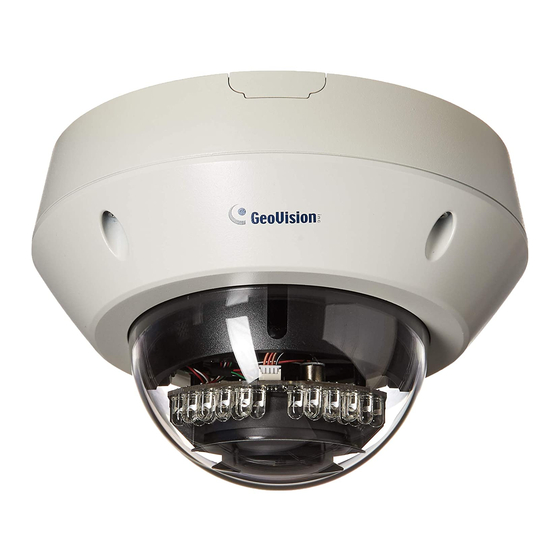
Page 16: Overview
1.3 Overview Figure 1-1 Name Description Turns on (green) when the power is on and Power LED turns off when there is no power supply. Turns on (green) when the system operates Status LED normally and turns off when system error occurs. - Page 17 Vandal Proof IP Dome (Part I) Name Description Rotational Screw Loosens to adjust the camera angle. Zoom Screw Adjusts the zoom of the camera. Focus Screw Adjusts the focus of the camera. Silica Gel Bag Absorbs moisture in the camera body.
-
Page 18: Installation
1.4 Installation The Vandal Proof IP Dome is designed for outdoors. With the standard package, there are two ways to install the Vandal Proof IP Dome: hard- ceiling mount and in-ceiling mount . Note: You can also install the camera: ... -
Page 19: Hard-Ceiling Mount
Vandal Proof IP Dome (Part I) 1.4.1 Hard-Ceiling Mount Figure 1-2 Unpack the camera package and take out the camera body. Unscrew the housing cover Unscrew thread lock... - Page 20 Unscrew the inner housing Take out the camera body...
- Page 21 Vandal Proof IP Dome (Part I) Mark the position of four screw holes on the desired installation location, and drill holes in the marked locations. Drill the ellipse part if you wish to put the wires through it. Figure 1-3 Insert the screw anchors to the 4 holes on the ceiling.
- Page 22 Connect the network, power and other cables to the camera. See 1.5 Connecting the Camera. Access the live view. See 2.1 Accessing the Live View, GV-IPCam H.264 Firmware Manual. Based on the live view, adjust the camera to a desired angle as illustrated below.
- Page 23 Rotational Adjustment Figure 1-7 10. Adjust image clarity using the GV-IP Device Utility program. For details, see 2.2 Adjusting Image Clarity, GV-IPCam H.264 Firmware Manual. 11. Screw on the thread lock as shown in step 1. 12. Replace the silica gel bag on the camera body within 2 minutes of opening the silica gel bag package.
- Page 24 Note: Adjust the black mask inside the housing cover to make sure the camera view is not obscured. IMPORTANT: The gel bag loses its effectiveness when the dry camera is opened. To prevent the lens from fogging up, replace the silica gel bag every time you open the camera and conceal the silica gel bag within 2 minutes of exposing to open air.
-
Page 25: In-Ceiling Mount
Vandal Proof IP Dome (Part I) 1.4.2 In-Ceiling Mount Figure 1-8 Follow step 1 in 1.4.1 Hard-Ceiling Mount section to remove the housing cover, thread lock and back cover, and take out the camera body. Cut out a circle with a diameter of 142 mm on the ceiling. Insert a blue screw to the indicated holes on the camera body. - Page 26 Screw in a plastic clip to the blue screw, hold it with one hand and use a screw driver to rotate the blue screw until the plastic clip moves half way down. Plastic Clip Figure 1-10 Secure a T-cap on top of the blue screw with a small screw cap and a T-cap screw.
- Page 27 Vandal Proof IP Dome (Part I) Insert the camera to the ceiling with the plastic screws moved inward. Figure 1-12 Move the blue screws out and rotate the blue screw with a screw driver until the plastic clip and the bottom of the camera body clamps the ceiling tightly.
-
Page 28: Connecting The Camera
1.5 Connecting the Camera Connect your Vandal Proof IP Dome to power, network and other cables needed. 1.5.1 Wire Definition The cables of Vandal Proof IP Dome are illustrated and defined below. Shielding ground DC 12V- / AC 24V- DC 12V+ / AC 24V+ Digital in (oragne) Digital out (brown) Ground (yellow) - Page 29 BNC wire to a monitor and select your signal format (NTSC or PAL) at the TV Out field on the Web interface. The default signal format is NTSC. For details, see 4.1.1 Video Settings, GV-IPCam H.264 Firmware Manual. The TV-out wire must be removed before you secure the housing...
-
Page 30: Power Connection
1.5.2 Power Connection There are two ways to supply power to the camera: Use a Power over Ethernet (PoE) adapter to connect the camera to the network, and the power will be provided at the same time. Plug the power adapter to the 12V terminal block as shown below. Insert the thin black wire of the Vandal Proof IP Dome to the left pin (-) and the red wire to the right pin (+). -
Page 31: Voltage Load Expansion (Optional)
Vandal Proof IP Dome (Part I) 1.5.3 Voltage Load Expansion (Optional) The camera can only drive a maximum load of 200mA 5V DC . To expand the maximum voltage load to 10A 250V AC , 10A 125V AC or 5A 100V DC , connect the camera to a GV-Relay V2 module (optional product). -
Page 32: Loading Factory Default
1.6 Loading Factory Default Keep the power and network cables (or PoE) connected to the camera. Use a pin to press and hold the default button on the inner housing. Release the default button when the status LED blinks. This shall take about 8 seconds. -
Page 33: Chapter 2 Vandal Proof Ip Dome (Part Ii)
Vandal Proof IP Dome (Part II) Chapter 2 Vandal Proof IP Dome (Part II) This chapter describes the features, physical overview and installation of GV-VD1530 / 2430 / 2530 / 3430, GV-VD1540 / 2440 / 2540 / 3440 / 5340 and GV-VD2540-E / 5340-E. - Page 34 Model No. Specification Description 1.3 MP Super Low Lux / 2 MP WDR GV-VD1530 Pro / 2 MP Super GV-VD2430 Varifocal Low Lux / 3 MP GV-VD2530 lens WDR Pro, H.264, GV-VD3430 Vandal Proof IP Dome 1.3 MP Super Low Auto Iris, Lux / 2 MP WDR GV-VD1540...
-
Page 35: Packing List
Vandal Proof IP Dome (Part II) 2.1 Packing List Vandal Proof IP Dome Torx Wrench 3-Pin Terminal Block Audio wires Power Adapter TV out wire RJ-45 Connector x 2 Back Plate Focus Adjustment Cap (for GV-VD1530 / 2430 / 2530 / 3430 only) - Page 36 Ruler Conduit Converter Plastic PG21 conduit connector Power Adepter GV-Vandal Proof IP Dome Hardware Installation Guide GV-NVR Software DVD GV-IPCAM H.264 Software Warranty Card Note: The power adapter can be excluded upon request.
- Page 37 Vandal Proof IP Dome (Part II) Note: You can choose to run the wires through a conduit pipe. After you have threaded all the wires, install the supplied conduit converter and plastic PG21 conduit connector with a self-prepared 1/2’’ conduit pipe to the camera.
-
Page 38: Features
2.2 Features Image sensor Camera Model Image Sensor GV-VD1530 / 1540 1/3" progressive scan super low lux CMOS GV-VD2430 / 2440 1/3.2" progressive scan CMOS GV-VD3430 / 3440 GV-VD2530 / 2540 1/2.8’’ progressive scan super low lux CMOS GV-VD2540-E GV-VD5340 1/2.5’’... - Page 39 Vandal Proof IP Dome (Part II) Ingress protection (IP67 rating) Wide temperature tolerance: -40°C ~ 50°C / -40°F ~ 122°F (for GV-VD2540-E / 5340-E) 3-axis mechanism (pan / tilt / roll) Micro SD card slot (SD/SDHC) for local storage ...
-
Page 40: Overview
2.3 Overview Figure 2-1... - Page 41 Vandal Proof IP Dome (Part II) Name Description The power LED (top) turns on (green) when the power is on and turns off when there is no power supply. The status LED (bottom) LED Indicators turns on (green) when the system operates normally and turns off when system error occurs.
-
Page 42: Installation
2.4 Installation The Vandal Proof IP Dome is designed for outdoors. With the standard package, you can install the camera on the ceiling. Note: You can also install the camera: on a power box (of the 4" square and double gang type) using the standard package ... - Page 43 Vandal Proof IP Dome (Part II) B. Unplug the conduit connector inside the housing and disintegrate the connector. You should have 4 parts: Figure 2-3 C. Remove the terminal block from the supplied power adapter. D. Thread the audio wires (optional), TV out wire (optional), adapter wires and I/O wires (optional) through the conduit entry and then through part 1, 2, 3 and 4 of the conduit connector.
- Page 44 2.6 mm: Audio, BNC 2 mm: DC12V / AC24V 1.8 mm: DIDO Figure 2-5 IMPORTANT: 1. Use the supplied ruler and leave about 10 cm of power and I/O wires between their connectors and the cable seal; leave at least 11 cm of audio/TV-out wires between their connectors and the cable seal.
- Page 45 Vandal Proof IP Dome (Part II) Install the Ethernet cable. A. Rotate to remove the indicated cap and the plug inside. Figure 2-6 B. Thread an Ethernet cable (the end with no RJ-45 connector) from the back panel through the cable seal Figure 2-7 IMPORTANT: Use the supplied ruler and leave about 11 cm of the Ethernet cable between the connector and the cable seal.
- Page 46 Connect the wires to the camera. Install the terminal blocks to the power adapter and I/O devices. See 2.5.1 Power Connection and 2.5.2 I/O Device Connections. Install the supplied RJ-45 connector to the Ethernet cable. Plug all the connectors to the camera panel. Tip: Unscrew the indicated screws and lift the camera to help you connect the wires.
- Page 47 Vandal Proof IP Dome (Part II) Sort out the wires at the back. You can have the wires come out from position A, B or both. The instructions here describe sorting wires for position A. Figure 2-8 From the back of the camera housing, unscrew and rotate the plate to one side, sort out the wires and secure the plate back.
- Page 48 Secure the back plate to the ceiling. A. Paste the sticker to the ceiling. The arrow on the sticker indicates the direction that the camera faces. Ceiling mount template Figure 2-10 B. Drill 3 holes for screws. The recommended ones are indicated as ‘1’.
- Page 49 (NTSC or PAL) at the TV Out field on the Web interface. The default signal format is NTSC. For details, see 4.1.1 Video Settings, GV-IPCam H.264 Firmware Manual. The TV-out wire must be removed before you secure the housing cover.
- Page 50 Secure the camera using the torx wrench Figure 2-12 Access the live view. See 2.1 Accessing the Live View, GV-IPCam H.264 Firmware Manual. Adjust the camera’s angle, focus and zoom of the camera. Pan Adjustment Figure 2-13...
- Page 51 Vandal Proof IP Dome (Part II) Tilt Adjustment Figure 2-14 Rotational Adjustment Figure 2-15...
- Page 52 10. Replace the silica gel bag and secure the camera cover using the torx wrench. IMPORTANT: The gel bag loses its effectiveness when the dry camera is opened. To prevent the lens from fogging up, replace the silica gel bag every time you open the camera and conceal the silica gel bag within 2 minutes of exposing to open air.
-
Page 53: Installation Of Weatherproof Shield
Vandal Proof IP Dome (Part II) 2.4.1 Installation of Weatherproof Shield Optionally purchase a weatherproof shield to protect the camera from rain and snow. Figure 2-16 Note: A weatherproof shield can be purchased upon request. The pan and tilt angle of the camera is limited by the shield. Remove the housing cover. - Page 54 Remove the three screws from the housing cover. Figure 2-18 Secure the three screws of the weatherproof shield to the housing cover. Weatherproof Shield Figure 2-19 Secure the housing cover.
-
Page 55: Connecting The Camera
2.5.2 I/O Device Connections The camera supports one digital input and one digital output of dry contact. Function Digital Output Digital Input Figure 2-21 For details on how to enable an installed I/O device, see 4.2 I/O Settings, GV-IPCam H.264 Firmware Manual. - Page 56 2.5.3 Voltage Load Expansion (Optional) The camera can only drive a maximum load of 200mA 5V DC . To expand the maximum voltage load to 10A 250V AC , 10A 125V AC or 5A 100V DC , connect the camera to a GV-Relay V2 module (optional product). Refer to the figure and table below.
-
Page 57: Loading Factory Default
Vandal Proof IP Dome (Part II) 2.6 Loading Factory Default Keep the power and network cables (or PoE) connected to the camera. Use a pin to press and hold the default button on the inner housing. Release the default button when the status LED blinks. This shall take about 8 seconds. -
Page 58: Chapter 3 Target Vandal Proof Ip Dome
Chapter 3 Target Vandal Proof IP Dome The Target Vandal Proof IP Dome is an outdoor camera designed with IK10 vandal resistance and IP67 ingress protection. The camera is equipped with an automatic IR-cut filter and IR LEDs for day and night surveillance. -
Page 59: Packing List
Target Vandal Proof IP Dome 3.1 Packing List Target Vandal Proof IP Dome Torx Wrench Screw x 4 Screw Anchor x 4 TV-Out Wire Audio Wires x 2 Installation sticker RJ-45 Connector Ceiling mount template ... - Page 60 Big Concave hexagon Wrench Small Concave hexagon Wrench Silica Gel Bag Sticker (for Silica Gel Bag) GV-IPCAM H.264 Software Ruler GV-NVR Software DVD Warranty Card Note: Power adapter can be purchased upon request.
- Page 61 Target Vandal Proof IP Dome Conduit converter Metal PG21 conduit connector ¾” Conduit pipe...
-
Page 62: Features
3.2 Features 1/2.8” progressive scan super low lux CMOS Min. illumination Camera Model Min. Illumination GV-EVD2100 0.004 lux GV-EVD3100 0.01 lux Dual streams from H.264 and MJPEG Frame Rate Camera Model Frame Rate GV-EVD2100 Up to 30 fps at 1920 x 1080 GV-EVD3100 Up to 30 fps at 2048 x 1536 ... - Page 63 Target Vandal Proof IP Dome Text overlay Privacy mask IP address filtering NAS recording Recording assigned by GV-Edge Recording Manager (Windows & Mac) Supports iPhone, iPad, Android & 3GPP 31 languages on Web interface ...
-
Page 64: Overview
3.3 Overview 13 12 Figure 3-1... - Page 65 Target Vandal Proof IP Dome Name Description The power LED (top) turns on (green) when the power is on and turns off when there is no power supply. The status LED (bottom) LED Indicators turns on (green) when the system operates normally and turns off when system error occurs.
-
Page 66: Installation
3.4 Installation The Target Vandal Proof IP Dome is designed for outdoors. With the standard package, you can install the camera on the ceiling. Note: You can also install the camera to ceilings, wall corners (concave or convex), and poles using optional mounting kits. For details on these installations, see GV-Mount Accessories Installation Guide on the Software DVD. - Page 67 Target Vandal Proof IP Dome Remove the back plate with the supplied torx wrench and remove the safety lock with a Philips screwdriver. Keep the removed screw for later use. Safety lock Figure 3-3 Thread an Ethernet cable and/or the adapter wire into the camera. Rotate to remove the indicated cap.
- Page 68 Figure 3-5 Thread an Ethernet cable (the end without RJ-45 connector) and/or the adapter wire from the back panel. Figure 3-6 If you are using PoE, thread an Ethernet cable through part 1 of the connector. If you are using DC 12V, change the connector to the supplied waterproof rubber set.
- Page 69 Target Vandal Proof IP Dome Thread the Ethernet cable and/or the adapter wire through part 2 and 3 of the connector. Figure 3-8 IMPORTANT: Use the supplied ruler and leave about 14 cm of the Ethernet cable and 10 cm of the adapter wire between the connector and the cable seal.
- Page 70 Thread the audio wires from the back panel, remove the plugs of part 1 and thread through the 3 parts of the connector. Plug Figure 3-10 Re-install the cap (part 3) with the supplied small concave hexagon wrench. Make sure the cap is installed tightly to waterproof the camera.
- Page 71 Target Vandal Proof IP Dome Connect the wires to the camera. Install the terminal block to the power adapter. See 3.5 Connection the camera. Install the supplied RJ-45 connector to the Ethernet cable. Plug all the connectors to the camera panel. Tip: Unscrew the indicated screws and lift the camera to help you connect the wires.
- Page 72 Secure the back plate to the ceiling. Paste the sticker to the ceiling. The arrow on the sticker indicates the direction that the camera faces. Ceiling mount template Figure 3-12 Drill 4 holes for screws. The recommended ones are indicated as ‘1’.
- Page 73 Target Vandal Proof IP Dome Secure the camera to the ceiling. Secure the safety lock to the camera with the screw you removed from the back plate in step 2. Safety lock Figure 3-13 Thread all the wires into the ceiling and connect them. Secure the camera with the torx wrench.
- Page 74 Access the live view. See 2.1 Accessing the Live View, GV-IPCam H.264 Firmware Manual. Note: The TV-out function can only be used during installation to adjust the focus of the camera. To use the TV out function, connect the supplied black BNC wire to a monitor and select your signal format (NTSC or PAL) at the TV Out field on the Web interface.
- Page 75 Target Vandal Proof IP Dome Tilt Adjustment Figure 3-16 Rotational Adjustment Figure 3-17...
- Page 76 11. Replace the silica gel bag, press all the wires and cables into the notch and secure the camera cover with the torx wrench. Figure 3-18 IMPORTANT: The gel bag loses its effectiveness when the dry camera is opened. To prevent the lens from fogging up, replace the silica gel bag every time you open the camera and conceal the silica gel bag within 2 minutes of exposing to open air.
-
Page 77: Connecting The Camera
Target Vandal Proof IP Dome 3.5 Connecting the Camera There are two ways to supply power to the camera: Use a Power over Ethernet (PoE) adapter to connect the camera to the network, and the power will be provided at the same time. ... -
Page 78: Loading Factory Default
3.6 Loading Factory Default Keep the power and network cables (or PoE) connected to the camera. Press and hold the default button for about 8 seconds. Release the default button when the status LED blinks. When the status LED fades, the process of loading default settings is completed and the camera reboots automatically.
Need help?
Do you have a question about the GV-IPCam H.264 and is the answer not in the manual?
Questions and answers