Table of Contents
Advertisement
SYSTXCCUIZ01-- V
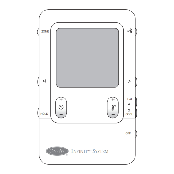
Infinityt Control
ZONE
HOLD
I
NFINITY
Fig. 1 - - Infinityt Zone Control
NOTE: Read the entire instruction manual before starting the
installation.
TABLE OF CONTENTS
. . . . . . . . . . . . . . . . . . . . . . . . . . . . . . . . . . .
. . . . . . . . . . . . . . . . . . . . . . . . . . . . . . . . . . . .
. . . . . . . . . . . . . . . . . . . . . . . . . . . . . . . .
. . . . . . . . . . . . . . . . . . . . . . . . . . . . . . . . . . . . .
. . . . . . . . . . . . . . . . . . . . . . . . . . . . . . . . . . . .
. . . . . . . . . . . . . . . . . . . . . . . . . . . . . . . . . . . . . .
. . . . . . . . . . . . . . . . . . . . . . . . . . . . . . .
. . . . . . . . . . . . . . . . . . . . . . . . . . . . . . . . . .
. . . . . . . . . . . . . . . . . . . . . . . . . . . . . .
Installation Instructions
HEAT
COOL
OFF
S
™
YSTEM
A04031
PAGE
. . . . . . . . . . . . . . . . . . . . . . . . .
. . . . . . . . . .
. . . . . . . . . . . . . .
. . . . . . . . . . . . . . . . . . . . . . . . .
. . . . . . . . . . . . . . . . . . . . . .
. . . . . . . . . . . . . . . . . . . . .
. . . . . . . . . . . . . . . . . .
SAFETY CONSIDERATIONS
Improper installation, adjustment, alteration, service, maintenance,
or use can cause explosion, fire, electrical shock, or other
conditions which may cause death, personal injury or property
damage. Consult a qualified installer, service agency or your
distributor or branch for information or assistance. The qualified
installer or agency must use factory- -authorized kits or accessories
when modifying this product. Refer to the individual instructions
packaged with the kits or accessories when installing.
Follow all safety codes. Wear safety glasses, protective clothing,
and work gloves. Have a fire extinguisher available. Read these
instructions thoroughly and follow all warnings and cautions
included in literature and attached to the unit. Consult local
building codes and the current edition of the National Electrical
Code (NEC) NFPA 70.
In Canada, refer to the current editions of the Canadian Electrical
Code CSA C22.1.
Recognize safety information. When you see this symbol
the unit and in instructions or manuals, be alert to the potential for
personal injury. Understand the signal words DANGER,
WARNING, and CAUTION. These words are used with the
safety- -alert symbol. DANGER identifies the most serious hazards,
which will result in severe personal injury or death. WARNING
signifies hazards, which could result in personal injury or death.
CAUTION is used to identify unsafe practices, which may result
in minor personal injury or product and property damage. NOTE
is used to highlight suggestions which will result in enhanced
installation, reliability, or operation.
The Infinity Zone System consists of several intelligent
1
communicating components which includes the Infinity Zone
1
Control (or User Interface), Smart Sensors, Damper Control
Module, variable speed furnace or FE fan coil, 2- -stage AC or HP
2
and Infinity Packaged Products, which continually communicate
2
with each other via a four- -wire connection called the ABCD bus.
4
Commands, operating conditions, and other data are passed
continually between components over the ABCD bus. The result is
6
a new level of comfort, versatility, and simplicity.
8
All Infinity furnaces or fan coils are variable- -speed and
9
multi- -stage for maximum flexibility, efficiency, and comfort. They
support controlled ventilation, humidification, dehumidification,
9
and air quality control. Either an Infinity (communicating) or a
9
standard 24VAC controlled outdoor unit may be used.
9
When using conventional outdoor units, the Infinity furnace or fan
14
coil provides the 24 volt signals needed to control them. Also, the
Infinity Damper Control Module (P/N SYSTXCC4ZC01) allows
15
connection of a Carrier HRV or ERV without the need for a
16
separate wall control.
19
All system components are controlled through the wall mounted
Infinity Zone Control, which replaces the conventional thermostat
20
and provides the homeowner with a single wall control for all
features of the system.
INTRODUCTION
on
Advertisement
Table of Contents

Related Manuals for Carrier INFINITY ZONING CONTROL


Summary of Contents for Carrier INFINITY ZONING CONTROL
-
Page 1: Table Of Contents
........connection of a Carrier HRV or ERV without the need for a OPERATIONAL INFORMATION . -
Page 2: Installation And Start- -Up Overview
Design Considerations S Close to a window, on an outside wall, or next to a door leading to the outside. The Infinity Zone system is unique because a bypass damper must not be used. This is possible due to the intelligence of the system S Exposed to direct light or heat from a lamp, sun, fireplace, or variable speed... - Page 3 than four wires in the event of a damaged or broken wire during NOTE: Always ensure the Infinity Zone Control location is installation. acceptable before cutting any holes in wall. Each communicating device in the Infinity Zone System has a Surface Mount four- -pin connector labeled ABCD.
-
Page 4: Installing Infinity Zone Control
Recessed terminal block in wall 1 " (38.1 mm) wide by 2 " (54 mm) high Recessed Mount Interlocking Tabs (4) A03185 A07150 Fig. 3 - - Infinityt Zone Control Fig. 7 - - Recessed Mount Assembly Surface Mount Backplate to wall Interlocking Tabs (4) A03191 A03186... - Page 5 Indoor Communicating Unit AC or HP Zone Control User Interface & Smart Sensor(s) Green Yellow A03193 A B C D Fig. 14 - - Wire ABCD Connector White CAUTION A B C D A B C D ELECTRICAL OPERATION HAZARD Humidifier Connection Failure to follow this caution may result in equipment damage...
-
Page 6: Initial Power- -Up
Heat Pump Charging screens under the Heat Pump “SEARCHING FOR OUTDOOR EQUIPMENT” (See Fig. 16). Checkout menu. Select “other” for non- -Carrier evaporators. Once the indoor and outdoor equipment has been found, the Selecting Electric Heater Installer will be asked to select Accessories. - Page 7 Zoning ELECTRIC HEATER NOT IDENTIFIED “SEARCHING FOR ZONE EQUIPMENT” will appear on the ENTER SIZE: 5 KW screen to identify the number of zones detected. This screen will NONE, 5,10,15 KW show Zone 1, Zone 2, etc. and indicate all zones having either a Remote Room Sensor, or smart sensors associated with them.
-
Page 8: Quick Start
NOTE: The static pressure check occurs only at initial installation, 10. Press the blue COOL button to select cooling humidity. or when INSTALL is run in the INSTALL/SERVICE menu. 11. Adjust the desired cooling humidity level using ei- ther(+/- -)button. Duct Assessment 12. -
Page 9: Install / Service Menus
INSTALL/SERVICE SETUP EQUIPMENT SUMMARY THERMOSTAT INSTALL FURNACE SETUP HEAT PUMP CHECKOUT ZONING SERVICE ACCESSORIES SYSTEM MAINTENANCE SOFTWARE VERSION 1 EXIT SELECT BACK SELECT A04089 A03200 Fig. 27 - - Setup Menu Fig. 24 - - Install / Service Menus Setup - - Thermostat NOTE: The INSTALL / SERVICE menu will automatically exit after 60 minutes of no push button activity. - Page 10 Install Settings: Low Heat Rise S Yes/No to reset install settings in Install/Service menus to factory S ON default settings. S OFF (default) Last 10 System Events: Set to ON if the system contains a bypass humidifier. The ON setting will increase the furnace low heat airflow. S Yes/No to reset last 10 system events under Service Info menu.
- Page 11 Setup - - Fan Coil Heat Pump Heating: S COMFORT (default) Heat Pump airflow is varied depending on outdoor temperature to maximize comfort. S EFF 325 - - fixed airflow used to achieve specified ratings - - no FE Fan Coil or dehumidification airflow reduction.
- Page 12 S FAN SPEED - - select Low, Med, High for all zones when G Turns on Quiet Shift function in 1- -stage or 2- -stage communicating heat pumps. terminal is energized. High Cool Latch: S SHUTDOWN - - shuts off fan and equipment when initiated. S OFF (default) This function is not intended for emergency fire shutdown.
- Page 13 FURNACE LOCKOUT - - Temperature above which the furnace HOT WATER LOCKOUT - - Outside temperature above which the will not operate, except for defrost. hot water will not operate except for defrost (if selected). S Default = NONE S Available settings - - NO, 5 to 55_F (- -15 to 13_C) in 1_ S Available settings = NONE thru >55_F (13_C) increments HEAT PUMP LOCKOUT - - Temperature below which the heat...
-
Page 14: Checkout Menus
Interval at which the Clean Ventilator Pre- -filter notification will S HIGH HEAT RUNTIME: 5 min. turn on. This menu item allows the furnace to be exercised. First, a low heat UV Lights Installed runtime and high heat runtime are selected. Range = 5 - - 120 min. S NO If only the low heat is to be exercised: S YES... -
Page 15: Service Menus
Charge Calculation (Appears with Variable NOTE: Selecting a lower airflow noise limit may decrease the homeowner’s comfort in that zone. Capacity Heat Pump) Sensor Types: S Calculates the amount of charge needed in the system. Takes Shows list of all zones with corresponding sensor types. into account lineset length, liquid line diameter, and indoor coil UI = User Interface model. -
Page 16: Operational Information
Cubic Feet per Minute of air the User Interface is currently HP = Heat Pump requesting. AC = Air Conditioner Blower RPM: FN = Furnace S Actual blower motor RPM value FC = Fan Coil Static Press: ZN1 = Zone Board 1 S Inches of water. - Page 17 Five- -Minute Compressor Timeguard Smart Recovery This timer prevents compressor from starting unless it has been off With Smart Recovery selected (factory default), transition out of for at least 5 minutes. It can be defeated by simultaneously pressing setback begins 1.5 hours before selected recovery time and the Fan and Temp + buttons.
- Page 18 Hybrid Heat Setup / Operation If the system determines that it cannot deliver the airflow into a zone that needs conditioning, and that zone has an airflow limit Furnace Lockout Operation — (in HYBRID HEAT SETUP selected, the system will take the following 4 steps: menu) is the outside temperature above which the furnace will not Step 1 —...
-
Page 19: Troubleshooting
TROUBLESHOOTING Please refer to the Troubleshooting Guide available on HVAC Partners for more detail. Infinity Zone Control does not power up. 1. Recheck wiring to ABCD on all devices. 2. Make sure all colors match for every terminal. 3. Make sure power is applied to the indoor unit, and the amber LED is lit on indoor control circuit board. 4. -
Page 20: System Malfunction Screen
While in service mode, the - -V model user disappear and the day/time will reappear. Catalog No: UIZ01---06SI Copyright 2011 Carrier Corp. S 7310 W. Morris St. S Indianapolis, IN 46231 Printed in China Edition Date: 04/11 Manufacturer reserves the right to change, at any time, specifications and designs without notice and without obligations.
Need help?
Do you have a question about the INFINITY ZONING CONTROL and is the answer not in the manual?
Questions and answers