D-Link DGS-1210-16 Reference Manual
Web smart switch
Hide thumbs
Also See for DGS-1210-16:
- Reference manual (109 pages) ,
- Product manual (71 pages) ,
- User manual (171 pages)
Table of Contents
Advertisement
Advertisement
Table of Contents

Related Manuals for D-Link DGS-1210-16


Summary of Contents for D-Link DGS-1210-16
- Page 2 Reproduction in any manner whatsoever without the written permission of D-Link Corporation is strictly forbidden. Trademarks used in this text: D-Link and the D-LINK logo are trademarks of D-Link Corporation; Microsoft and Windows are registered trademarks of Microsoft Corporation. Other trademarks and trade names may be used in this document to refer to either the entities claiming the marks and names or their products.
-
Page 3: Table Of Contents
Table of Contents D-Link Web Smart Switch User Manual Table of Contents Table of Contents ............................. i Intended Readers ............................. 1 Terms/Usage ..............................1 Safety Instructions ............................1 General Precautions for Rack-Mountable Products ..................2 Protecting Against Electrostatic Discharge ....................3 Product Introduction .......................... - Page 4 Table of Contents D-Link Web Smart Switch User Manual Tool Bar > Tools Menu ..........................21 Reset ................................ 21 Reset System ............................21 Reboot Device ............................22 Configuration Backup and Restore ......................22 Firmware Backup and Upgrade ........................ 22 Language Management ........................... 23 Tool Bar >...
- Page 5 Table of Contents D-Link Web Smart Switch User Manual L2 Functions > LLDP > LLDP Local Port Table ..................56 L2 Functions > LLDP > LLDP Remote Port Table ................... 57 L2 Functions > LLDP > LLDP Statistics ....................59 L3 Functions >...
- Page 6 Table of Contents D-Link Web Smart Switch User Manual To connect a switch via TELNET: ......................103 To connect a switch via SSH: ........................103 Logging on to the Command Line Interface: ....................103 CLI Commands: ............................103 ? ................................104 download ..............................
-
Page 7: Intended Readers
Intended Readers D-Link Web Smart Switch User Manual Intended Readers This guide provides instructions to install the D-Link Gigabit Web Smart Switch DGS-1210-08P/16/24/24P/48, how to configure Web-based Management step-by-step. NOTE: The model you have purchased may appear slightly different from the illustrations shown in the document. -
Page 8: General Precautions For Rack-Mountable Products
Product Introduction D-Link Web Smart Switch User Manual An object has fallen into the product. The product has been exposed to water. The product has been dropped or damaged. The product does not operate correctly when you follow the operating instructions. -
Page 9: Protecting Against Electrostatic Discharge
Product Introduction D-Link Web Smart Switch User Manual • Systems are considered to be components in a rack. Thus, "component" refers to any system as well as to various peripherals or supporting hardware. • Before working on the rack, make sure that the stabilizers are secured to the rack, extended to the floor, and that the full weight of the rack rests on the floor. -
Page 10: Product Introduction
Web-Based management interface that allows administrators to remotely control their network down to the port level. The D-Link Network Assistant (DNA) is a program that allows administrators to quickly discover all D-Link smart switches and D-Link Discover Protocol (DDP) supported devices that are in the same subnet as the PC, collect traps and log messages, and provide quick access to basic configurations of the switch. -
Page 11: Dgs-1210-08P
Product Introduction D-Link Web Smart Switch User Manual DGS-1210-08P 8-Port 10/100/1000Mbps PoE plus 2 SFP Slot Web Smart Switch. Front Panel Figure 1.1 – DGS-1210-08P Front Panel Power LED : The Power LED lights up when the Switch is connected to a power source. -
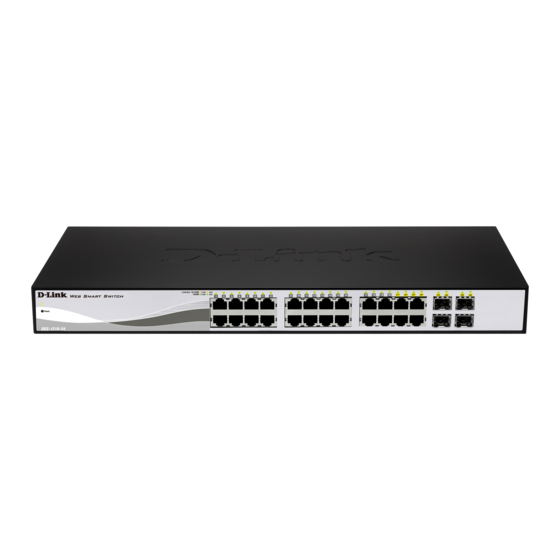
Page 12: Dgs-1210-16
16-Port 10/100/1000Mbps plus 4 SFP Slot Web Smart Switch. Front Panel Figure 1.3 – DGS-1210-16 Front Panel Power LED : The Power LED lights up when the Switch is connected to a power source. Port Link/Act/Speed LED (1-20): The Link/Act/Speed LED flashes, which indicates a network link through the corresponding port. -
Page 13: Rear Panel
Product Introduction D-Link Web Smart Switch User Manual Port Link/Act/Speed LED (1-28): The Link/Act/Speed LED flashes, which indicates a network link through the corresponding port. Blinking indicates that the Switch is either sending or receiving data to the port. When a port has an amber light, this indicates that the port is running on 10M or 100M. When it has a green light it is running on 1000M. -
Page 14: Rear Panel
Product Introduction D-Link Web Smart Switch User Manual Rear Panel Figure 1.8 DGS-1210-24P Rear Panel Power: Connect the supplied AC power cable to this port. Security Lock: Provide a Kensington-compatible security lock to be able to connect to a secure immovable device. -
Page 15: Hardware Installation
Screws and two mounting brackets One Multi-lingual Getting Started Guide One CD with Web UI Reference Guide, Getting Started Guide, D-Link Network Assistant User Guide, Language Pack Files, and D-View Module. If any item is found missing or damaged, please contact the local reseller for replacement. -
Page 16: Step 3: Plugging In The Ac Power Cord With Power Cord Clip
Hardware Installation D-Link Web Smart Switch User Manual Then, use the screws provided with the equipment rack to mount the switch in the rack. Figure 2.3 – Mount the Switch in the rack or chassis Please be aware of following safety Instructions when installing: A) Elevated Operating Ambient - If installed in a closed or multi-unit rack assembly, the operating ambient temperature of the rack environment may be greater than room ambient. - Page 17 Hardware Installation D-Link Web Smart Switch User Manual Figure 2.4 – Insert Tie Wrap to the Switch B) Plug the AC power cord into the power socket of the Switch. Figure 2.5 – Connect the power cord to the Switch C) Slide the Retainer through the Tie Wrap until the end of the cord.
- Page 18 Hardware Installation D-Link Web Smart Switch User Manual D) Circle the tie of the Retainer around the power cord and into the locker of the Retainer. Figure 2.7 – Circle around the power cord E) Fasten the tie of the Retainer until the power cord is secured.
-
Page 19: Power Failure
Hardware Installation D-Link Web Smart Switch User Manual Figure 2.9 – Plugging the switch into an outlet Power Failure As a precaution, the switch should be unplugged in case of power failure. When power is resumed, plug the switch back in. -
Page 20: Getting Started
This chapter introduces the management interface of D-Link Web-Smart Switch. Management Options The D-Link Web Smart Switch can be managed through any port on the device by using the Web-based Management. Each switch must be assigned its own IP Address, which is used for communication with the Web-Based Management or a SNMP network manager. -
Page 21: Login Web-Based Management
English. For more information about language packs, refer to Language Management. Figure 3.3 – Logon Dialog Box Smart Wizard After a successful login, the Smart Wizard will guide you through essential settings of the D-Link Web Smart Switch. Please refer to the Smart Wizard Configuration section for details. Web-based Management By clicking the Exit button in the Smart Wizard, you will enter the Web-based Management interface. - Page 22 Getting Started D-Link Web Smart Switch User Manual NOTE: Please be sure to uninstall any existing DNA from your PC before installing the latest DNA. For detailed explanations of the DNA functions, please refer to D-Link Network Assistant (DNA) User Guide.
-
Page 23: Configuration
Configuration D-Link Web Smart Switch User Manual Configuration The features and functions of the D-Link Web Smart Switch can be configured for optimum use through the Web-based Management Utility. Smart Wizard Configuration After a successful login, the Smart Wizard will guide you through essential settings of the D-Link Web Smart Switch. -
Page 24: Password
Configuration D-Link Web Smart Switch User Manual Password Type the desired new password in the Password field and again in the Confirm Password field, then click the Next button to the SNMP setting page. Figure 4.2 – Password in Smart Wizard... -
Page 25: Snmp
Configuration D-Link Web Smart Switch User Manual SNMP The SNMP Setting allows you to quickly enable or disable the SNMP function. The default SNMP Setting is Disabled. Click Enabled and then click Apply to make it effective. Figure 4.3 – SNMP in Smart Wizard NOTE: Changing the system IP address will disconnect you from the current connection. -
Page 26: Web-Based Management
Logout button first, then it will be seen as an abnormal exit and the login session will still be occupied. Finally, by clicking on the D-Link logo at the upper-left corner of the screen you will be redirected to the local D-Link website. -
Page 27: Tool Bar > Save Menu
Configuration D-Link Web Smart Switch User Manual Tool Bar > Save Menu The Save Menu provides Save Configuration and Save Log functions. Figure 4.6 – Save Menu Save Configuration Select to save the entire configuration changes you have made to the device to switch’s non-volatile RAM. -
Page 28: Reboot Device
Configuration D-Link Web Smart Switch User Manual Reboot Device Provide a safe way to reboot the system. Click Apply to restart the Switch. Figure 4.12 – Tools Menu > Reboot Device Configuration Backup and Restore Allow the current configuration settings to be saved to a file (not including the password), and if necessary, you can restore the configuration settings from this file. -
Page 29: Language Management
Configuration D-Link Web Smart Switch User Manual Figure 4.14 – Tools Menu > Firmware Backup and Upgrade HTTP: Backup or upgrade the firmware to or from your local PC drive. Click Backup to save the firmware to your disk. Click Browse to browse your inventories for a saved firmware file. -
Page 30: Tool Bar > Smart Wizard
Tool Bar > Online Help The Online Help provides two ways of online support: D-Link Support Site will lead you to the D-Link website where you can find online resources such as updated firmware images; User Guide can offer an immediate reference for the feature definition or configuration guide. -
Page 31: Function Tree
Configuration D-Link Web Smart Switch User Manual Function Tree All configuration options on the Switch are accessed through the Function Tree. Click the setup item that you want to configure. The following sections provide more detailed description of each feature and function. -
Page 32: System > System Settings
Configuration D-Link Web Smart Switch User Manual Figure 4.18 – Device Information It also offers an overall status of common software features: RSTP: Click Settings to link to L2 Functions > Spanning Tree > STP Global Settings. Default is disabled. -
Page 33: System > Password
Configuration D-Link Web Smart Switch User Manual IP Information: There are three ways for the Switch to obtain an IP address: Static, DHCP (Dynamic Host Configuration Protocol) and BOOTP. When using the static mode, the IP Address, Subnet Mask and Gateway can be manually configured. - Page 34 Configuration D-Link Web Smart Switch User Manual Figure 4.21 – System > Port Settings Speed: Gigabit Fiber connections can operate in 1000M Full, Auto or Disabled. Copper connections can operate in Forced Mode settings (1000M Full, 100M Full, 100M Half, 10M Full, 10M Half), Auto, or Disabled.
-
Page 35: System > Dhcp Auto Configuration
Configuration D-Link Web Smart Switch User Manual System > DHCP Auto Configuration This window allows you to enable the DHCP Auto Configuration feature on the Switch. When enabled, the Switch becomes a DHCP client and gets the configuration file from a TFTP server automatically on next boot up. -
Page 36: System > Power Saving
Configuration D-Link Web Smart Switch User Manual Figure 4.24 – System > Time Profile Profile Name: Specifies the profile name. Time(HH MM): Specifies the Start Time and End Time. Weekdays: Specifies the week days. Date: Select Date and specifies the From Day and To Day of the time profile. -
Page 37: System > Ieee802.3Az Eee Settings
Configuration D-Link Web Smart Switch User Manual Port Shut-off - The Port Shut-off state has high priority (the priority rule is the same as LED.) Therefore, if the Port Shut-off sate is already disabled, the Time Profile function will not take effect. -
Page 38: System > Dns Resolver Settings
Configuration D-Link Web Smart Switch User Manual System > DNS Resolver Settings This window allows configuring Domain Name Server (DNS) resolver. The DNS Resolver State is Disabled by default. Click Enabled to enable DNS resolver. Click Apply for the changes to take effect. -
Page 39: Vlan > 802.1Q Vlan Pvid
Configuration D-Link Web Smart Switch User Manual Figure 4.29 – Configuration > 802.1Q VLAN > Add VLAN VID: Enter a VLAN ID. VLAN Name: Enter a name of VLAN. Port: Click to assign ports as Untag, Tag, or Not Member. A port can be untagged in only one VID. - Page 40 Configuration D-Link Web Smart Switch User Manual Figure 4.32 – VLAN > Voice VLAN > Voice VLAN Global Settings Voice VLAN: Select to enable or disable Voice VLAN. The default is Disabled. After you enabled Voice VLAN, you can configure the Voice VLAN Global Settings.
-
Page 41: Vlan > Voice Vlan > Voice Vlan Port Settings
Configuration D-Link Web Smart Switch User Manual Select the OUI and press Add to the lower table to complete the Auto Voice VLAN setting. NOTE: Voice VLAN has higher priority than any other features (including QoS). Therefore the voice traffic will be operated according to the Voice VLAN setting and not impacted by the QoS feature. -
Page 42: Vlan > Voice Vlan > Voice Device List
Similar as Voice VLAN, Auto Surveillance VLAN is a feature that allows you to automatically place the video traffic from D-Link IP cameras to an assigned VLAN to enhance the IP surveillance service. With a higher priority and individual VLAN, the quality and the security of surveillance traffic are guaranteed. The Auto Surveillance VLAN function will check the source MAC address on the incoming packets. -
Page 43: L2 Functions > Jumbo Frame
L2 Functions > Jumbo Frame D-Link Gigabit Web Smart Switches support jumbo frames (frames larger than the Ethernet frame size of 1536 bytes) of up to 13,004 bytes (tagged). Default is Disabled. Click Enabled, and then Apply to turn on the jumbo frame support. -
Page 44: L2 Functions > Loopback Detection
Configuration D-Link Web Smart Switch User Manual TX (transmit) mode: Duplicates the data transmitted from the source port and forwards it to the Target Port. Click All to include all ports into port mirroring. RX (receive) mode: Duplicates the data that is received from the source port and forwards it to the Target Port. -
Page 45: L2 Functions > Mac Address Table > Static Mac
Configuration D-Link Web Smart Switch User Manual Enabled VLANs: This is used to configure the loopback detection function for the VLANs on VLAN-based mode. Enter the list of VLAN used for this configuration. Tick the All VLANs check box to enable this option on all the VLANs configured on the Switch. -
Page 46: L2 Functions > Spanning Tree > Stp Global Settings
Configuration D-Link Web Smart Switch User Manual Figure 4.40 – L2 Functions > MAC Address Table > Dynamic Forwarding Table L2 Functions > Spanning Tree > STP Global Settings The Switch implements two versions of the Spanning Tree Protocol, the Rapid Spanning Tree Protocol (RSTP) as defined by the IEEE 802.1D-2004 specification and a version compatible with the IEEE 802.1D-... -
Page 47: L2 Functions > Spanning Tree > Stp Port Settings
Configuration D-Link Web Smart Switch User Manual Figure 4.41 – L2 Functions > Spanning Tree > STP Global Settings STP Version: You can choose RSTP or STP Compatible. The default setting is RSTP. Bridge Priority: This value, between 0 and 61440, specifies the priority for forwarding packets. The lower the value, the higher the priority. - Page 48 Configuration D-Link Web Smart Switch User Manual Figure 4.42 – L2 Functions > Spanning Tree > STP Port Settings From Port/To Port: A consecutive group of ports may be configured starting with the selected port. State: Use the drop-down menu to enable or disable STP by per-port based. It will be selectable after the global STP is enabled.
-
Page 49: L2 Functions > Link Aggregation > Port Trunking
Configuration D-Link Web Smart Switch User Manual Restricted Role: Toggle between True and False to set the restricted role state of the packet. If set to True, the port will never be selected to be the Root port. The default value is False. -
Page 50: L2 Functions > Multicast > Igmp Snooping
Configuration D-Link Web Smart Switch User Manual Figure 4.44 – L2 Functions > Link Aggregation > LACP Port Settings From Port / To Port: A consecutive group of ports may be configured starting with the selected port. Activity: There are two different roles of LACP ports: Active - Active LACP ports are capable of processing and sending LACP control frames. - Page 51 Configuration D-Link Web Smart Switch User Manual Figure 4.45 – L2 Functions > Multicast > IGMP Snooping By default, IGMP is Disabled. If enabled, the IGMP Global Settings will need to be entered: Host Timeout (130-153025): This is the interval after which a learned host port entry will be purged. For each host port learned, a 'Port Purge Timer' runs for 'Host Port Purge Interval'.
-
Page 52: L2 Functions > Multicast > Mld Snooping
Figure 4.46 – L2 Functions > Multicast > IGMP Snooping VLAN Settings State: Specify the State to be enabled or disabled. Querier State: D-Link Smart Switch is able to send out the IGMP Queries to check the status of multicast clients. The default state is Disabled. - Page 53 Configuration D-Link Web Smart Switch User Manual Figure 4.48 – L2 Functions > Multicast > MLD Snooping By default, MLD is Disabled. If enabled, the MLD Global Settings will need to be entered: Host Timeout (130-153025): This is the interval after which a learned host port entry will be purged. For each host port learned, a 'Port Purge Timer' runs for 'Host Port Purge Interval'.
-
Page 54: L2 Functions > Multicast > Multicast Forwarding
Figure 4.49 – L2 Functions > Multicast > MLD Snooping VLAN Settings State: Specify the State to be enabled or disabled. Querier State: D-Link Smart Switch is able to send out the MLD Queries to check the status of multicast clients. The default state is Disabled. -
Page 55: L2 Functions > Multicast > Multicast Filtering Mode
Configuration D-Link Web Smart Switch User Manual Multicast MAC Address: The MAC address of the static source of multicast packets. This must be a multicast MAC address. Port: Allows the selection of ports that will be members of the static multicast group. -
Page 56: L2 Functions > Sntp > Time Zone Settings
Configuration D-Link Web Smart Switch User Manual SNTP - Indicates that the system time is retrieved from a SNTP server. Current Time: Displays the current date and time for the switch. If choosing SNTP for the clock source, then the following parameters will be available: SNTP First Server: Specifies the IPv4 or IPv6 address of the primary SNTP server from which the system time is retrieved. -
Page 57: L2 Functions > Lldp > Lldp Global Settings
Configuration D-Link Web Smart Switch User Manual L2 Functions > LLDP > LLDP Global Settings LLDP (Link Layer Discovery Protocol) provides IEEE 802.1AB standards-based method for switches to advertise themselves to neighbor devices, as well as to learn about neighbor LLDP devices. SNMP utilities can learn the network topology by obtaining the MIB information in each LLDP device. -
Page 58: L2 Functions > Lldp > Lldp Port Settings
Configuration D-Link Web Smart Switch User Manual From Port/ To Port: A consecutive group of ports may be configured starting with the selected port. Extended PSE TLV: Select to enable or disable the extended PSE TLV option. Click Apply to implement the changes made. Click Refresh to refresh the table information. -
Page 59: L2 Functions > Lldp > 802.3 Extension Tlv
Configuration D-Link Web Smart Switch User Manual Figure 4.58 – L2 Functions > LLDP > 802.1 Extension TLV Port Settings From Port / To Port: A consecutive group of ports may be configured starting with the selected port. Port VLAN ID: Specifies the port VLAN ID TLV to be enabled or disabled. -
Page 60: L2 Functions > Lldp > Lldp Management Address Settings
Configuration D-Link Web Smart Switch User Manual Figure 4.59 – L2 Functions > LLDP > 802.3 Extension TLV Port Settings From Port / To Port: A consecutive group of ports may be configured starting with the selected port. MAC/PHY Configuration/Status: Specifies that the LLDP agent should transmit the MAC/PHY configuration/status TLV. -
Page 61: L2 Functions > Lldp > Lldp Management Address Table
Configuration D-Link Web Smart Switch User Manual Figure 4.60 – L2 Functions > LLDP > LLDP Management Address Settings From Port / To Port: A consecutive group of ports may be configured starting with the selected port. Address Type: Select the IP address type here. Options to choose from are IPv4 and IPv6. -
Page 62: L2 Functions > Lldp > Lldp Local Port Table
Configuration D-Link Web Smart Switch User Manual L2 Functions > LLDP > LLDP Local Port Table The LLDP Local Port Table window displays LLDP local port information. Figure 4.62 – L2 Functions > LLDP > LLDP Local Port Brief Table Port: Displays the port number. -
Page 63: L2 Functions > Lldp > Lldp Remote Port Table
Configuration D-Link Web Smart Switch User Manual Figure 4.64 – L2 Functions > LLDP > LLDP Local Port Detailed Table L2 Functions > LLDP > LLDP Remote Port Table This LLDP Remote Port Table page is used to display the LLDP Remote Port Brief Table. Select port number and click Search to display the detail information of the port. - Page 64 Configuration D-Link Web Smart Switch User Manual Figure 4.66 – L2 Functions > LLDP > LLDP Remote Port Normal Table To view the detailed information for a remote port, click View Detailed and the following page displays.
-
Page 65: L2 Functions > Lldp > Lldp Statistics
Configuration D-Link Web Smart Switch User Manual Figure 4.67 – L2 Functions > LLDP > LLDP Remote Port Detailed Table L2 Functions > LLDP > LLDP Statistics The LLDP Statistics window displays an overview of all LLDP traffic. - Page 66 Configuration D-Link Web Smart Switch User Manual Figure 4.68 – L2 Functions > LLDP > LLDP Statistics The following information can be viewed: LLDP Statistics System: Displays the counters that refer to the whole switch. Last Change Time – Displays the time for when the last change entry was last deleted or added. It is also displays the time elapsed since last change was detected.
-
Page 67: L3 Functions > Ipv6 System Settings
Configuration D-Link Web Smart Switch User Manual L3 Functions > IPv6 System Settings The IPv6 System Settings window allows users to configure the IPv6 system settings for this Switch. Figure 4.69 – L3 Functions > IPv6 System Settings IPv6 System Settings: Interface Name: Displays the IPv6 interface name. -
Page 68: L3 Functions > Ipv6 Neighbor Settings
Configuration D-Link Web Smart Switch User Manual Default Gateway: Enter the IPv6 default gateway address here. Metric: Enter the metric value for this route here. Click Create to create a new IPv6 route. Click Delete to remove the corresponding route. -
Page 69: L3 Functions > Dhcp > Dhcpv6 Relay Settings
Configuration D-Link Web Smart Switch User Manual Figure 4.72 – L3 Functions > DHCP > DHCP Relay Settings DHCP Relay Global Settings: DHCP Relay State: Use the drop-down menu to toggle between Enabled and Disabled. It is used to enable or disable the DHCP Relay service on the Switch. -
Page 70: Qos > Bandwidth Control
Configuration D-Link Web Smart Switch User Manual DHCPv6 Relay Hops Count Limit (1-32): This field allows an entry between 1 and 32. If the message received by the relay agent is a Relay-forward message and the hop-count in the message is greater than or equal to the Relay Hops Count Limit, the relay agent discards the received message. -
Page 71: Qos > 802.1P/Dscp/Tos
Configuration D-Link Web Smart Switch User Manual QoS > 802.1p/DSCP/ToS QoS is an implementation of the IEEE 802.1p standard that allows network administrators to reserve bandwidth for important functions that require a larger bandwidth or that might have a higher priority, such as VoIP (voice-over Internet Protocol), web browsing applications, file server applications or video conferencing. -
Page 72: Qos > Ipv6 Traffic Class Priority Settings
Configuration D-Link Web Smart Switch User Manual When ToS is selected in Select QoS Mode, the following selections appear. From ToS / To ToS: Select a consecutive ToS. Priority: Defines the priority assigned to the port. The priorities are Highest, High, Medium and Low. -
Page 73: Security > Port Security
Configuration D-Link Web Smart Switch User Manual Figure 4.78 – Security > Trusted Host Trusted Host: Specify the Trusted Host to be enabled or disabled. The default is disabled. To define a management station IP setting, click the Add button and type in the IPv4 address and Subnet mask or IPv6 address and Prefix value. -
Page 74: Security > Dos Attack Prevention
Configuration D-Link Web Smart Switch User Manual From Port / To Port: A consecutive group of ports may be configured starting with the selected port. Admin State: Use the drop-down menu to enable or disable Port Security (locked MAC address table for the selected ports). -
Page 75: Security > Traffic Segmentation
Click Select All button to check all ports. Click Clear to uncheck all ports. Security > Safeguard Engine D-Link’s Safeguard Engine is a robust and innovative technology that automatically throttles the impact of packet flooding into the switch's CPU. This function helps protect the Web-Smart Switch from being interrupted by malicious viruses or worm attacks. -
Page 76: Security > Storm Control
Configuration D-Link Web Smart Switch User Manual Security > Storm Control The Storm Control feature provides the ability to control the receive rate of broadcast, multicast, and unknown unicast packets. Once a packet storm has been detected, the Switch will drop packets coming into the Switch until the storm has subsided. -
Page 77: Security > Dhcp Server Screening
Configuration D-Link Web Smart Switch User Manual Figure 4.84 – Security > ARP Spoofing Prevention Enter the IP Address, MAC Address, Ports and then click Add to create a checking/filtering rule. Click Delete to remove the corresponding rule. Click Delete All to clear all the entries. -
Page 78: Security > Ssl
Configuration D-Link Web Smart Switch User Manual Security > SSL Secure Sockets Layer (SSL) is a security feature that provides a secure communication path between a Web Management host and the Switch Web UI by using authentication, digital signatures and encryption. These security functions are implemented by Ciphersuite, a security string that determines the cryptographic parameters, encryption algorithms and key sizes. -
Page 79: Security > Smart Binding > Smart Binding
Configuration D-Link Web Smart Switch User Manual Figure 4.87 – Security > Smart Binding > Smart Binding Settings The Smart Binding Settings page contains the following fields: From Port/ To Port: Select a range of ports to set for IP-MAC-port binding. -
Page 80: Security > Smart Binding > White List
Configuration D-Link Web Smart Switch User Manual Figure 4.88 – Security > Smart Binding > Smart Binding Manual Binding: IPv4 Address: Specifies the IPv4 address to bind to the MAC address set below. IPv6 Address: Specifies the IPv6 address to bind to the MAC address set below. -
Page 81: Aaa > 802.1X > 802.1X Settings
Configuration D-Link Web Smart Switch User Manual Figure 4.90 – Security > Smart Binding > Black List By giving conditions, desired devices information can be screened out below and then click Find to search for a list of the entry: VID: Enter the VLAN ID number of the device. - Page 82 Configuration D-Link Web Smart Switch User Manual Figure 4.91 – AAA > 802.1X > 802.1X Settings 802.1X: By default, 802.1X is disabled. To use EAP for security, click Enabled and set the 802.1X Global Settings. To establish 802.1X port-specific assignments, click Enabled and configure 802.1X Port Access Control.
-
Page 83: Aaa > 802.1X > Guest Vlan Settings
Configuration D-Link Web Smart Switch User Manual Auto - If Auto is selected, it will enable 802.1X and cause the port to begin in the unauthorized state, allowing only EAPOL frames to be sent and received through the port. The authentication process begins when the link state of the port transitions from down to up, or when an EAPOL-start frame is received. -
Page 84: Acl > Acl Wizard
Configuration D-Link Web Smart Switch User Manual Confirm Key: Re-type the key which is the same as that of the RADIUS server. Click Apply to implement the changes made. ACL > ACL Wizard Access Control List (ACL) allows you to establish criterion to determine whether or not the Switch will forward packets based on the information contained in each packet's header. -
Page 85: Acl > Access Profile List
Configuration D-Link Web Smart Switch User Manual Press Apply for the settings to take effect. NOTE: Once the ACL rules conflict, rules with the smaller rule ID will take higher priority. NOTE: careful configuration. Inappropriate design may lead to management access failure. - Page 86 Configuration D-Link Web Smart Switch User Manual Figure 4.96 – Add Access Profile The steps of adding an access profile are described below: 1) After selecting the Select Profile ID and Select Frame Type (MAC ACL, IPv4 ACL, or IPv6 ACL), specify attributes like Untagged/Tagged (for MAC), ICMP/IGMP/TCP/UDP/Protocol-ID (for IPv4), or ICMP/TCP/UDP (for IPv6).
- Page 87 Configuration D-Link Web Smart Switch User Manual UDP: Specifies UDP as the Layer 3 protocol that the access profile checks. Protocol ID: Specifies Protocol ID as the Layer 3 protocol that the access profile checks. IPv6 ACL – Select to instruct the Switch to examine the IPv6 address in each frame’s header.
- Page 88 Configuration D-Link Web Smart Switch User Manual Figure 4.99 – ACL > Access Profile List > Add ACL Profile (IPv4 ACL ICMP) The Add ACL Profile IPv4 ACL ICMP address window contains the following fields: IPv4 TOS: Select this option to include IPv4 type of service parameters in this profile.
- Page 89 Configuration D-Link Web Smart Switch User Manual To define the IPv4 ACL IGMP profile, Select IPv4 ACL with IGMP and click Select button. The following window displays: Figure 4.100 – ACL > Access Profile List > Add ACL Profile (IPv4 ACL IGMP) The Add ACL Profile IPv4 ACL IGMP address window contains the following fields: IPv4 TOS: Select this option to include IPv4 type of service parameters in this profile.
- Page 90 Configuration D-Link Web Smart Switch User Manual To define the IPv4 ACL TCP profile, Select IPv4 ACL with TCP and click Select button. The following window displays: Figure 4.101 – ACL > Access Profile List > Add ACL Profile (IPv4 ACL TCP) The Add ACL Profile IPv4 ACL TCP port window contains the following fields: IPv4 TOS: Select this option to include IPv4 type of service parameters in this profile.
- Page 91 Configuration D-Link Web Smart Switch User Manual To define the IPv4 ACL UDP profile, Select IPv4 ACL with UDP and click Select button. The following window displays: Figure 5.92 – ACL > Access Profile List > Add ACL Profile (IPv4 ACL UDP) The Add ACL Profile IPv4 ACL UDP port window contains the following fields: IPv4 TOS: Select this option to include IPv4 type of service parameters in this profile.
- Page 92 Configuration D-Link Web Smart Switch User Manual To define the IPv4 ACL Protocol ID profile, Select IPv4 ACL with Protocol-ID and click Select button. The following window displays: Figure 4.102 – ACL > Access Profile List > Add ACL Profile (IPv4 ACL Protocol ID) The Add ACL Profile IPv4 Protocol ID contains the following fields: IPv4 TOS: Select this option to include IPv4 type of service parameters in this profile.
- Page 93 Configuration D-Link Web Smart Switch User Manual Figure 4.103 – ACL > Access Profile List > Add ACL Profile (IPv6 ACL ICMP) The Add ACL Profile IPv6 ACL ICMP address window contains the following fields: IPv6 Class: Tick this option to include the IPv6 class field.
- Page 94 Configuration D-Link Web Smart Switch User Manual To define the IPv6 ACL TCP profile, Select IPv6 ACL with TCP and click Select button. The following window displays: Figure 4.104 – ACL > Access Profile List > Add ACL Profile (IPv6 ACL TCP) The Add ACL Profile IPv6 ACL TCP port window contains the following fields: IPv6 Class: Tick this option to include the IPv6 class field.
- Page 95 Configuration D-Link Web Smart Switch User Manual To define the IPv6 ACL UDP profile, Select IPv6 ACL with UDP and click Select button. The following window displays: Figure 5.92 – ACL > Access Profile List > Add ACL Profile (IPv4 ACL UDP) The Add ACL Profile IPv4 ACL UDP port window contains the following fields: IPv6 Class: Tick this option to include the IPv6 class field.
- Page 96 Configuration D-Link Web Smart Switch User Manual Figure 4.105 – Confirmation of Creating Access Profile List NOTE: You cannot select Payload in a MAC ACL, or L2 Header in IP ACL. 3) After the Profile ID has been created, click Continue to go back to the main Access Profile List window.
-
Page 97: Acl > Acl Finder
Configuration D-Link Web Smart Switch User Manual Type – Displays the type of rule. MAC, or IP. VLAN ID – Specifies the VLAN ID. Destination MAC Address - Enter a destination MAC address. Source MAC Address - Enter a source MAC address. -
Page 98: Poe > Poe Global Settings (Dgs-1210-08P/24P Only)
The DGS-1210-24P supplies power to PD devices up to 30 Watt for ports 1 to 12, meeting IEEE 802.3af and 802.3at standards. The DGS-1210-08P supplies power to PD devices up to 15.4 Watt for ports 1 to 8. The DGS-1210-24P works with all D-Link 802.3af or 802.3at capable devices. The DGS-1210-08P works with all D-Link 802.3af devices. -
Page 99: Snmp > Snmp > Snmp Global Settings
Configuration D-Link Web Smart Switch User Manual a port. DGS-1210-08P/24P will auto disable the ports if port current is over 375mA in 802.3af mode or 625mA in pre-802.3at mode. Note: The PoE Status information of Power current, Power Voltage, and Current is the power usage information of the connected PD;... -
Page 100: Snmp > Snmp > Snmp User
Configuration D-Link Web Smart Switch User Manual presentation of the information controlled by the on-board SNMP agent. SNMP defines both the format of the MIB specifications and the protocol used to access this information over the network. The default SNMP global state is disabled. Select Enabled and click Apply to enable the SNMP function. -
Page 101: Snmp > Snmp > Snmp Group
Configuration D-Link Web Smart Switch User Manual Privacy Protocol/Password: Specify either none or DES and then enter a password for SNMPv3 encryption in the right column. Click Add to create a new SNMP user account. Click Delete to remove the corresponding entry. -
Page 102: Snmp > Snmp > Snmp Community
Configuration D-Link Web Smart Switch User Manual Figure 4.114 – SNMP > SNMP > SNMP View View Name: Name of the view, up to 32 characters. Subtree OID: The Object Identifier (OID) Subtree for the view. The OID identifies an object tree (MIB tree) that will be included or excluded from access by an SNMP manager. -
Page 103: Snmp > Snmp > Snmp Engine Id
Configuration D-Link Web Smart Switch User Manual Figure 4.116 – SNMP > SNMP > SNMP Host Host IP Address: Specifies the IPv4 or IPv6 address of the SNMP management host. SNMP Version: Select the SNMP version to be used to the management host. -
Page 104: Snmp > Rmon > Rmon History
Configuration D-Link Web Smart Switch User Manual Owner: Displays the RMON station or user that requested the RMON information. Click Add to create a new entry. Click Refresh to renew the table information. Click Delete to remove the corresponding entry. -
Page 105: Snmp > Rmon > Rmon Event
Configuration D-Link Web Smart Switch User Manual Interval (1 ~ 2^31-1): Defines the alarm interval time in seconds. Sample type: Defines the sampling method for the selected variable and comparing the value against the thresholds. The possible field values are: Delta value –... - Page 106 Configuration D-Link Web Smart Switch User Manual Figure 4.123 – Monitoring > Port Statistics TxOK: Number of packets transmitted successfully. RxOK: Number of packets received successfully. TxError: Number of transmitted packets resulting in error. RxError: Number of received packets resulting in error.
-
Page 107: Monitoring > Cable Diagnostics
Configuration D-Link Web Smart Switch User Manual To view the statistics of individual ports, click one of the linked port numbers for details. Figure 4.124 – Monitoring > Port Statistics Click Back to go back to the previous page. Click Refresh to renew the information. Click Clear to reset the details. -
Page 108: Monitoring > System Log
Configuration D-Link Web Smart Switch User Manual • Short in Cable means the wires of the RJ45 cable may be in contact somewhere. • Open in Cable means the wires of RJ45 cable may be broken, or the other end of the cable is simply disconnected. -
Page 109: Command Line Interface
D-Link Web Smart Switch User Manual Command Line Interface The D-Link Web Smart Switch allows a computer or terminal to perform some basic monitoring and configuration tasks by using the Command Line Interface (CLI) via the TELNET or SSH protocol. - Page 110 Command Line Interface D-Link Web Smart Switch User Manual Command Parameter logout [<ipaddr> | <domain_name 255>] {times <value 1-255> | timeout <sec 1- ping 99>} <ipv6addr> {times <value 1-255> | size <value 1-6000> | timeout <sec 1- ping6 99>} reboot...
-
Page 111: Download
Command Line Interface D-Link Web Smart Switch User Manual DGS-1210-24:admin#? USEREXEC commands : config account admin password <password> config ipif System { ipaddress <ip-address> <subnet-mask> gateway <gw- address>| dhcp | bootp} config ipif System { ipv6 ipv6address <ipv6networkaddr> | dhcpv6_client {enable... -
Page 112: Upload
Command Line Interface D-Link Web Smart Switch User Manual Restrictions None. Example usage: To download a firmware file: DGS-1210-24:admin#download firmware_fromTFTP 10.90.90.10 RUNTIME Connecting to server....Done. Download firmware...... Done. Do not power off! Please wait, programming flash..Done. DGS-1210-24:admin# Note: Switch will reboot after the restore and all current configurations will be lost. -
Page 113: Config Ipif System
Command Line Interface D-Link Web Smart Switch User Manual DGS-1210-24:admin#upload firmware_toTFTP 10.90.90.10 RUNTIME Connecting to server....Done. Upload firmware......Done. DGS-1210-24:admin# config ipif System Purpose This command is used to configure the System IP interface. Syntax config ipif System [ipaddress <ip-address> <subnet-mask>... -
Page 114: Ping
Command Line Interface D-Link Web Smart Switch User Manual To terminate the current user’s console session: DGS-1210-24:admin#logout ********** * Logout * ********** NOTE: Save your configuration changes before logging out. ping Purpose This command is used to test the connectivity between the Switch and other network devices. -
Page 115: Ping6
Command Line Interface D-Link Web Smart Switch User Manual ping6 Purpose This command is used to test the IPv6 connectivity between the Switch and other network devices. Syntax ping6 <ipv6addr> {times <value 1-255> | size <value 1-6000> | timeout <sec 1-99>}... -
Page 116: Reset Config
Command Line Interface D-Link Web Smart Switch User Manual DGS-1210-24:admin#reboot Are you sure you want to proceed with the system reboot?(y/n) y % Device will reboot, please wait a few minutes to re-login. Success. DGS-1210-24:admin# reset config Purpose This command is used to reset the Switch’s configuration to the factory default settings. -
Page 117: Show Switch
Command Line Interface D-Link Web Smart Switch User Manual DGS-1210-24:admin#show ipif IP Setting Mode : Static IP Address : 10.90.90.90 Subnet Mask : 255.0.0.0 Default Gateway : 10.90.90.1 DHCPv6 Client State : Disabled IPv6 Link-Local Address : FE80::280:C2FF:FE12:2400/128 DGS-1210-24:admin# show switch Purpose This command is used to display information about the Switch. -
Page 118: Save
Command Line Interface D-Link Web Smart Switch User Manual Example usage: To configure the administrator user account password used on the Switch: DGS-1210-24:admin#config account admin password 1234 DGS-1210-24:admin# save Purpose This command is used to save changes made in the Switch’s configuration to the non-volatile RAM. - Page 119 Command Line Interface D-Link Web Smart Switch User Manual DGS-1210-24:admin#debug info % segmentation fault log file : File doesn't exist !!! % ARP table : Address Hardware Address Type Interface Mapping ------- ---------------- ---- --------- ------- 10.0.0.0 FF-FF-FF-FF-FF-FF ARPA System Local/Broadcast 10.90.90.6...
-
Page 120: Appendix A - Ethernet Technology
Appendix A - Ethernet Technology D-Link Web Smart Switch User Manual Appendix A - Ethernet Technology This chapter will describe the features of the D-Link Web Smart Switch and provide some background information about Ethernet/Fast Ethernet/Gigabit Ethernet switching technology. Gigabit Ethernet Technology Gigabit Ethernet is an extension of IEEE 802.3 Ethernet utilizing the same packet structure, format, and... -
Page 121: Appendix B - Technical Specifications
Appendix B - Technical Specifications D-Link Web Smart Switch User Manual Appendix B - Technical Specifications - DEM-315GT (1000BASE-ZX, SM, 80km) Hardware Specifications WDM Transceivers Supported: Key Components / Performance - DEM-330T/R (1000BASE-BX, TX- Switching Capacity: 1550/RX-1310nm, SM, 10km) - DGS-1210-08P: 20Gbps... -
Page 122: L3 Features
Appendix B - Technical Specifications D-Link Web Smart Switch User Manual L3 Features DHCP Server Screening: Able to configure 5 IP addresses for DHCP server. DHCP Relay SSL: Support v1/v2/v3 IPv6 Smart Binding VLAN Supports manual configuration and 802.1Q VLAN standard (VLAN Tagging) scanning for binding. - Page 123 Appendix B - Technical Specifications D-Link Web Smart Switch User Manual switches save most power since main chipsets (both MAC and PHY) are disabled for all ports, and energy required to power the CPU is minimal. - Power saving by Time-based PoE: PoE ports can be turned on/off by port or system through schedules.
Need help?
Do you have a question about the DGS-1210-16 and is the answer not in the manual?
Questions and answers