D-Link DGS-1224T Manual
D-link systems 24-port 10/100/1000mbps gigabit ethernet switch + 2-port mini gbic web-smart switch manual dgs-1224t
Hide thumbs
Also See for DGS-1224T:
- User manual (61 pages) ,
- Quick installation manual (9 pages) ,
- Product manual (52 pages)

Related Manuals for D-Link DGS-1224T


Summary of Contents for D-Link DGS-1224T
- Page 1 D-Link DGS-1224T 24-Port 10/100/1000Mbps Gigabit Ethernet Switch + 2-Port mini GBIC Web-Smart Switch Manual Second Edition Building Networks for People...
-
Page 3: Table Of Contents
TABLE OF CONTENT About This Guide... 1 Purpose ... 1 Terms/Usage ... 1 Introduction... 3 Gigabit Ethernet Technology ... 3 Fast Ethernet Technology ... 4 Switching Technology ... 5 VLAN (Virtual Local Area Network)... 6 Features... 6 Unpacking and Installation ... 9 Unpacking... - Page 4 Installing the Web Management Utility... 17 Discovery List... 18 Monitor List ... 19 Device Setting... 21 Toolbar... 22 Configuring the Switch ... 23 Login... 24 Setup Menu ... 25 Configuring Setup Setting... 27 Port Settings... 27 VLAN Settings (Virtual Local Area Network) ... 29 Trunk Setting ...
- Page 5 Technical Specifications ... 37...
-
Page 7: About This Guide
Fast Ethernet and 10Mbps Ethernet network capabilities in a highly flexible package. Purpose This guide discusses how to install and configure the DGS-1224T Web Smart Switch. Terms/Usage In this guide, the term “Switch” (first letter upper case) refers to your DGS-1224T Web Smart Switch, and “switch”... -
Page 9: Introduction
INTRODUCTION This chapter describes the features of the DGS-1224T and some background information about Ethernet/Fast Ethernet/Gigabit Ethernet switching technology. Gigabit Ethernet Technology Gigabit Ethernet is an extension of IEEE 802.3 Ethernet utilizing the same packet structure, format, and support for CSMA/CD protocol,... -
Page 10: Fast Ethernet Technology
tomorrow’s rapidly improving switching and routing internetworking technologies. And with expected advances in the coming years in silicon technology and digital signal processing that will enable Gigabit Ethernet to eventually operate over unshielded twisted-pair (UTP) cabling, outfitting your network with a powerful 1000-Mbps- capable backbone/server connection creates a flexible foundation for the next generation of network technology products. -
Page 11: Switching Technology
Switching is a cost-effective way of increasing the total network capacity available to users on a local area network. A switch increases capacity and decreases network loading by dividing a local area network into different segments, which don’t compete with each other for network transmission capacity. -
Page 12: Vlan (Virtual Local Area Network)
Cost Reduction, VLANs can be used to create multiple broadcast domains, thus eliminating the need of expensive routers. Port-based (or port-group) VLAN is the common method of implementing a VLAN, and is the one supplied in the Switch. Features 24×10/100/1000Mbps Auto-negotiation Gigabit Ethernet ports... - Page 13 Up to 8K unicast addresses entities per device, self-learning, and table aging 512KBytes packet buffer Supports IEEE 802.3x flow control for full-duplex mode ports Supports IEEE 802.1Q-based VLAN Supports IEEE 802.1P-based QoS Supports Port-trunking Supports Port-mirroring Supports Port-setting for Speed/Disable, Flow control and Port priority Support Jumbo-frame setting Supports IEEE 802.1D Spanning Tree protocol...
-
Page 15: Unpacking And Installation
The site where you install the hub stack may greatly affect its performance. When installing, consider the following pointers: Install the Switch in a fairly cool and dry place. See Technical Specifications for the acceptable temperature and humidity operating ranges. -
Page 16: Rack Mounting
Leave at least 10cm of space at the front and rear of the hub for ventilation. Install the Switch on a sturdy, level surface that can support its weight, or in an EIA standard-size equipment rack. For information on rack installation, see the next section, Rack Mounting. -
Page 17: Connecting Network Cable
AC Power The Switch used the AC power supply 100-240V AC, 50-60 Hz. The power switch is located at the rear of the unit adjacent to the AC power connector and the system fan. The switch’s power supply will adjust to the local power source automatically and may be turned on... -
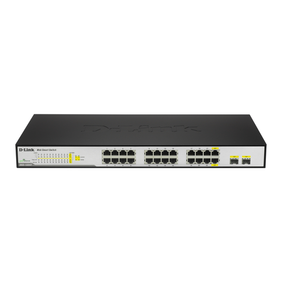
Page 19: Identifying External Components
This chapter describes the front panel, rear panel, and LED indicators of the Switch. Front Panel The figure below shows the front panels of the Switch. Figure 4. Front panel of 24-port Gigabit Ethernet Switch LED Indicator: Comprehensive LED indicators display the status of the switch and the network (see the LED Indicators chapter below). -
Page 20: Rear Panel
Rear Panel Figure 5. Rear panel of the Switch AC Power Connector: This is a three-pronged connector that supports the power cord. Plug in the female connector of the provided power cord into this connector, and the male into a power outlet. Supported input voltages range from 100-240V AC at 50-60Hz. -
Page 21: Understanding Led Indicators
Figure 6. LED indicators of the Switch Power and System LEDs POWER: Power Indicator : When the Power LED lights on, the Switch is receiving power. : When the Power turns off or the power cord has improper connection. CPU: Management Indicator Blinking : When the CPU is working, the System LED is blinking. -
Page 22: Ports 1~24 Status Leds
Ports 1~24 Status LEDs Link/ACT: Link/Activity When the Link/ACT LED lights on, the respective port is successfully connected to an Ethernet network. Blinking When the Link/ACT LED is blinking, the port is transmitting or receiving data on the Ethernet network. No link. -
Page 23: Configuration
CONFIGURATION Through the Web Browser you can configure the Switch such as VLAN, Trunking, QoS… etc. With the attached Web Management Utility, you can easily discover all the Web Management Switch, assign the IP Address, changing the password and upgrading the new firmware. -
Page 24: Discovery List
Figure 7. Web Management Utility The Web Management Utility was divided into four parts, Discovery List, Monitor List, Device Setting and Toolbar function, for details instruction, follow the below section. Discovery List This is the list where you can discover all the Web management devices in the entire network. -
Page 25: Monitor List
System word definitions in the Discovery List: MAC Address: Shows the device MAC Address. IP Address: Shows the current IP address of the device. Protocol version: Shows the version of the Utility protocol. Product Name: Shows the device product name. System Name: Shows the appointed device system name. - Page 26 Figure 9. Trap information Note: In order to receive Trap information, switch has to be configured with Trap IP and Trap Events in Web browser, which are available in the Trap Setting Menu (see Page 46 for detail).
-
Page 27: Device Setting
Device Setting You can set the device by using the function key in the Device Setting Dialog box. Configuration Setting: In this Configuration Setting, you can set the IP Address, Subnet Mask, Gateway, Set Trap to (Trap IP Address), System name and Location. Select the device in the Discovery list or Monitor List and press this button, then the Configuration Setting window will pop out as Figure 10... -
Page 28: Toolbar
Firmware Upgrade: When the device has a new function, there will be a new firmware to update the device, use this function to update. Figure 12. Firmware Upgrade Web Access: Double click the device in the Monitor List or select a device in the Monitor List and press this “Web Access”... -
Page 29: Configuring The Switch
In the “Help TAB”, there is About function, it will show out the version of the Web Management Utility. Configuring the Switch The DGS-1224T Web Smart Switch has a Web GUI interface for smart switch configuration. The Switch can be configured through the Web Browser. A network administrator can manage, control and monitor the switch from the local LAN. -
Page 30: Login
PC must be set on same the IP network. For example, when the default network address of the default IP address of the Web Smart Switch is 192.168.0.1, then the manager PC should be set at 192.168.0.x (where x is a number between 2 and 254), and the default subnet mask is 255.255.255.0. -
Page 31: Setup Menu
After entering the password, the main page comes up, the screen will display the device status. Figure 15. Device Status Setup Menu When the main page appears, find the Setup menu in the left side of the screen ( ). Click on the setup item that you want to Figure 16 configure. - Page 32 Figure 16. Setup menu...
-
Page 33: Configuring Setup Setting
Configuring Setup Setting Find that there are eight items, including Port Settings, VLAN Settings, Trunk Settings, Mirror Settings, QoS Setting, Spanning Tree Setting, SNMP Setting and Jumbo Frame Setting in Setup menu. Port Settings In Port Settings menu ( ), this page will show each port’s status, Figure 17 press the ID parameter to set each port’s Speed, Flow Control, QoS priority and Link Status. - Page 34 Half, Auto and Disable—for speed or port disable selections. Flow Control: This setting determines whether or not the Switch will be handling flow control. Set FlowCtrl to Enable for avoiding data transfer overflow. Or it sets to Disable; there is either no flow control or other hardware/software management.
-
Page 35: Vlan Settings (Virtual Local Area Network)
VLAN Settings (Virtual Local Area Network) VID Table Setting: select the VID group that you set. When you select VID Table Setting, press “Add new VID” to create new VID group, from port 01 ~ port 24, select Untag Port, Tag Port or Not Member for each port. -
Page 36: Trunk Setting
Figure 20. 802.1Q Port VID Setting Trunk Setting The Trunk function enables to cascade two or more devices with a larger bandwidths. There are three Trunk groups to be set; and there are default ports in each member. Checked “Enable” to use the trunk function, select the ports in each member to be trunk, and click “Apply”... -
Page 37: Mirror Setting
Port Mirroring is a method of monitoring network traffic that forwards a copy of each incoming and/or outgoing packet from one port of a network switch to another port where the packet can be studied. It enables the manager to keep close track of switch performance and alter it if necessary. - Page 38 Both (transmit and receive) mode: this mode will duplicate both the data transmit from and data that send to the source port, then it will forward to the sniffer port. Figure 22. Mirror setting...
-
Page 39: Ieee 802.1P Qos Setting
IEEE 802.1P QoS Setting To set the Switch QoS base on IEEE 802.1p, Figure 23. IEEE 802.1P-based QoS setting Spanning Tree Setting This Switch supports the 802.1d Spanning Tree Protocol. Every segment will have a single path to the root bridge. All bridges listen for BPDU packets. - Page 40 LAN. If the value ages out and a BPDU has still not been received from the Root Bridge, the Switch will start sending its own BPDU to all other switches for permission to become the Root Bridge. If it turns out that your switch has the lowest Bridge Identifier, it will become the Root Bridge.
-
Page 41: Snmp Setting
MIB specifications and the protocol used to access this information over the network. The Switch supports the SNMP versions 1. In SNMP v.1, user authentication is accomplished using 'community strings', which function like passwords. The remote user SNMP application and the Switch SNMP must use the same community string. - Page 42 Traps Traps are messages that alert network personnel of events that occur on the Switch. The events can be as serious as a reboot (someone accidentally turned OFF the Switch), or less serious like a port status change. The Switch generates traps and sends them to the trap recipient (or network manager).
- Page 43 SNMP Community / Trap: To configure the SNMP Community or SNMP Trap configuration. Configure SNMP Community: Figure 25. SNMP Community Setting Add Group: To add a SNMP Community group, press “Add Group” button, the Add SNMP Community configuration window will pop out; fill in the community name and assign the community enable read_only or read_write.
- Page 44 configuration window will pop out; checked the delete dialog box. Press “Apply” to delete the selected SNMP Community Group. Figure 27. Delete SNMP Community group Modify Group: To modify previously defined SNMP Community group, click on the ID parameter to enter to the selected SNMP Community Group to configure its community name and community enable.
- Page 45 Trap Set window will pop out; you can fill in the community name and trap IP address of the remote management station that will serve as the SNMP host for the Switch and checked the events selection to enabled selected event traps.
- Page 46 Figure 31. Delete SNMP Trap...
-
Page 47: Jumbo Frame Setting
IP address and events. Press “Apply” to save change of the SNMP Trap. Figure 32. Modify SNMP Trap Jumbo Frame Setting To enable or disable the Jumbo Frame function on the Switch. Figure 33. Jumbo frame setting... -
Page 48: Device Status
Device Status Click on the “Status” to present the device status on this screen, it will show the System Status, Port Status, VLAN Status, Trunk Status and Mirror Status. Figure 34. Device Status Press “Refresh” when you need to renew the posted information. -
Page 49: Statistic
Statistic The Statistic Menu screen will show the status of each port packet count. Figure 35. Statistic For Detail packet information, click on the ID parameter as Figure 36... -
Page 50: System Setting
Figure 36. System Setting The System Setting includes the System name, Location name, Login Timeout, IP Address, Subnet Mask and Gateway. Through the Web Management Utility, you can easily recognize the device by using the System Name and the Location Name. The Login Timeout is to set the idle time-out for security issue, when there is no action in running the Web Smart Utility and the time is up, you must re-login to Web Smart Utility before you set the Utility. - Page 51 Figure 37. System Setting...
-
Page 52: Trap Setting
Trap Setting The Trap Setting enables the device to monitor the Trap through the Web Management Utility, set the Trap IP Address of the manager where the trap to be sent. Figure 38. Trap Setting System Events: Monitoring the system’s trap. Device Bootup: a trap when booting up the system. -
Page 53: Set Password
If you forget the password, press the “Reset” button in the rear panel of the Switch, the current setting includes VLAN, Port Setting… etc. will be lost and the Switch will restore to the default setting. Figure 39. Set Password... -
Page 54: Backup Setting
Backup Setting The backup tools help you to backup the current setting of the Switch. Once you need to backup the setting, press the “Backup” button to save the setting. To restore a current setting file to the device, you must specify the backup file and press “Restore”... -
Page 55: Logout
Logout When press this function, the web configuration will go back to first Login page. Figure 42. Logout... -
Page 57: Physical And Environmental
TECHNICAL SPECIFICATIONS General Standards IEEE 802.3 10BASE-T Ethernet IEEE 802.3u 100BASE-TX Fast Ethernet IEEE 802.3ab 1000BASE-T Gigabit Ethernet IEEE 802.3x Full Duplex Flow Control IEEE 802.3z 1000BASE-SX/LX Gigabit Ethernet Protocol CSMA/CD Data Transfer Rate Ethernet: 10Mbps (half duplex), 20Mbps (full-duplex) Fast Ethernet: 100Mbps (half duplex), 200Mbps (full-duplex) Gigabit Ethernet: 2000Mbps (full-duplex) Topology... - Page 58 Performance Transmits Method: Store-and-forward Filtering Address Table: 8K entries per device Packet 1000Mbps Gigabit Ethernet: 1,488,000/pps Filtering/Forwarding Rate: MAC Address Learning: Automatic update Transmits Method: Store-and-forward RAM Buffer: 512K bytes per device...
- Page 59 The customer must submit with the product as part of the claim a written description of the Hardware defect or Software nonconformance in sufficient detail to allow D-Link to confirm the same, along with proof of purchase of the product (such as a copy of the dated purchase invoice for the product) if the product is not registered.
- Page 60 Warranty provides specific legal rights and you may also have other rights which vary from state to state. Trademarks: D-Link is a registered trademark of D-Link Systems, Inc. Other trademarks or registered trademarks are the property of their respective owners.
- Page 61 Product Registration Register online your D-Link product at http://support.dlink.com/register/ Product registration is entirely voluntary and failure to complete or return this form will not diminish your warranty rights.
-
Page 62: International Offices
Australia 1 Giffnock Avenue North Ryde, NSW 2113 Australia TEL: 61-2-8899-1800 FAX: 61-2-8899-1868 URL: www.dlink.com.au India D-Link House, Kurla Bandra Complex Road Off CST Road, Santacruz (East) Mumbai - 400098 India TEL: 91-022-26526696/56902210 FAX: 91-022-26528914 URL: www.dlink.co.in Middle East (Dubai) P.O.Box: 500376... -
Page 63: Registration Card All Countries And Regions Excluding Usa
8. What category best describes your company? Aerospace Engineering Education Retail/Chain store/Wholesale System house/company Other________________________________ 9. Would you recommend your D-Link product to a friend? Don't know yet 10.Your comments on this product? __________________________________________________________________________________________ __________________________________________________________________________________________ Registration Card * Product installed in type of...
Need help?
Do you have a question about the DGS-1224T and is the answer not in the manual?
Questions and answers