Husqvarna P520 D Operator's Manual

Husqvarna P520 D Operator's Manual

Hide thumbs Also See for P520 D:
Table of Contents

Advertisement

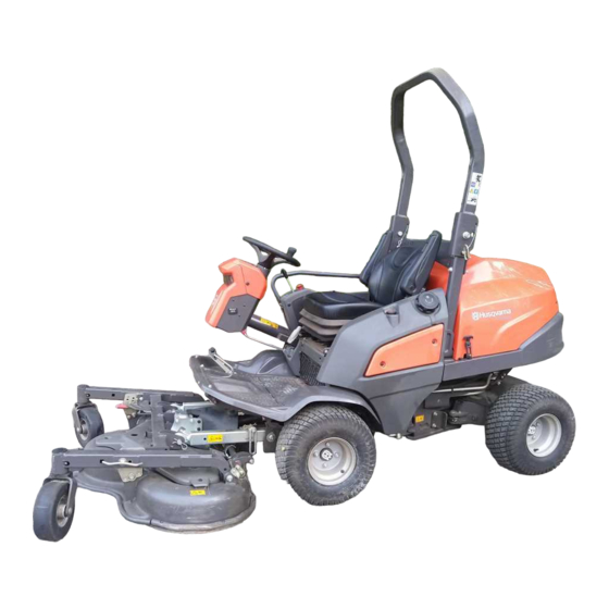
Oper ator ' s manual
P520 D
P525 D
Please r ead the operator's manual carefully and make sure you
understand the instructions before using the machine.
E E E E n n n n g g g g l l l l i i i i s s s s h h h h

Advertisement

Table of Contents
loading

Summary of Contents for Husqvarna P520 D

  • Page 1 Oper ator ′ s manual P520 D P525 D Please r ead the operator’s manual carefully and make sure you E E E E n n n n g g g g l l l l i i i i s s s s h h h h...
  • Page 2: Key To Symbols

    KEY TO SYMBOLS Symbols Parking brake These symbols are on the machine and in the instructions. Noise emission to the environment WARNING! Careless or incorrect use can according to the European Community’s result in serious or fatal injury to the Directive.
  • Page 3: Explanation Of Warning Levels

    KEY TO SYMBOLS Explanation of warning levels Risk of crush injuries! The warnings are graded in three levels. WARNING! Danger of crushing between the lift arms and base plate. WARNING! Used if there is a risk of serious injury or death for the operator or damage to the surroundings if the instructions in the manual are not followed.
  • Page 4: Table Of Contents

    CONTENTS Contents Stop the engine ............MAINTENANCE AND SERVICE KEY TO SYMBOLS Maintenance schedule ..........Symbols ............... General ................ Explanation of warning levels ........Cleaning ............... CONTENTS Checking the engine’s cooling air intake ...... Contents ..............Cleaning the radiator cell package ....... Service journal Cleaning the air filter ............
  • Page 5: Service Journal

    Service journal Pre-delivery service 14 Tell customer about: The requirement and advantages of servicing the 1 Charge the battery for at least 4 hours at max. 3 machine according to the service plan amp. Servicing and the influence of this journal on the 2 Check coolant level and antifreeze.
  • Page 6: Presentation

    Dear Customer, Thank you for choosing a Husqvarna Rider. Husqvarna Riders are built to a unique design with a front-mounted cutting unit and a patented articulated steering. Riders are designed for maximum efficiency even in small or confined areas. The closely grouped controls and pedal-operated hydrostatic transmission also contribute to the performance of this machine.
  • Page 7: Good Service

    Good service Husqvarna products are sold all over the world and ensures that you, the customer, get the best support and service. For example, before this machine was delivered it was inspected and adjusted by your dealer. See the certificate in the Service Journal in this manual.
  • Page 8: What Is What

    WHAT IS WHAT? 18 19 24 25 20 21 22 23 14 15 16 17 What is what on the machine? 1 Knob for seatback angle 14 Counter 2 Throttle trigger 15 Temperature gauge 3 Power outlet 16 Knob for adjustment of the seat suspension 4 Switch for the power outlet 17 Lever for longitudinal seat adjustment 5 Control for cutting unit drive...
  • Page 9: Machine´s Safety Equipment

    MACHINE´S SAFETY EQUIPMENT General Safety circuit The machine has a safety circuit that triggers whenever the driver gets off the seat while the blades are engaged. The WARNING! Never use a machine that has safety circuit is also tripped when the parking brake has not faulty safety equipment! been applied and the driver rises from the seat.
  • Page 10: Parking Brake

    MACHINE´S SAFETY EQUIPMENT Catch (P 525D) ROPS (Roll Over Protective Structure) ROPS is a protective frame that reduces the risk of injury in the event of overturning. Use ROPS and a safety belt when driving on slopes. The frame can be folded down. •...
  • Page 11: Safety Belt

    MACHINE´S SAFETY EQUIPMENT ROPS check Checking the protective covers • Check that the ROPS is securely attached and not • Check the protective covers for cracks or other damages. damaged. Replace damaged covers. Safety belt The seat belt protects the driver from injury in case of crashes or overturning.
  • Page 12: Assembling And Adjustments

    ASSEMBLING AND ADJUSTMENTS Safety when assembling and Fitting the cutting head settings 1 Place the machine on a flat surface and apply the parking brake. 2 Start the engine and lower the lift arms to floating mode. WARNING! The engine emits carbon monoxide, which is a colourless, poisonous gas.
  • Page 13 ASSEMBLING AND ADJUSTMENTS 8 Insert the bolts for the link joints and the pins on both 15 Fit the lifting eyes which are attached to the lift arms. Pull sides. out the catch and press in the lifting eye. There is one for each lift arm.
  • Page 14: Removing The Cutting Unit

    ASSEMBLING AND ADJUSTMENTS Removing the cutting unit 9 Slide the ring sideways to release the quick coupling and the universal drive shaft can be pulled from the shaft pin. WARNING! Never leave the universal drive shaft of the machine with one end loose. If the engine is started, damage can occur.
  • Page 15: Seat Adjustment

    ASSEMBLING AND ADJUSTMENTS Seat adjustment • Seatback angle is adjusted with the knob on the right side. WARNING! Take care so that hands are not trapped or injured by the locking hooks when the seat is folded back. WARNING! Do not adjust seat settings while driving.
  • Page 16: Fuel Handling

    FUEL HANDLING General • Allow the engine to cool before refuelling. • Check the fuel level before each use and leave space for the fuel to expand, because the heat from the engine and WARNING! Running an engine in a confined the sun may otherwise cause the fuel to expand and or badly ventilated area can result in death overflow.
  • Page 17: Operating

    OPERATING General safety precautions • Serious accidents may occur if you fail to be on your guard for children in the vicinity of the machine. Children are often attracted to the machine and mowing. Never • Read all the instructions in this operator’s manual and on assume that children will remain where you last saw them.
  • Page 18: Other Protective Equipment

    OPERATING Other protective equipment Instrument panel • Make sure that you have first aid equipment close at hand The indicator lights are on the steering console under the when using the machine. steering wheel. • Fire Extinguisher Work safety • Make sure nobody else is in the vicinity of the machine when you start the engine, engage the drive or drive off.
  • Page 19: Driving The Rider

    OPERATING Driving the Rider Adjusting the cutting height The cutting height can be adjusted to seven different positions. WARNING! Make sure that branches do not Select the required cutting height (1-7) using the cutting obstruct the pedals when mowing under height adjusters.
  • Page 20: Lights And Power Outlet

    OPERATING Transport position • Avoid starting or stopping on a slope. If the tyres start to slip, stop the blades and drive slowly down the slope. • Stop the blades by pressing in the control for driving the • Always drive smoothly and slowly on slopes. cutting unit.
  • Page 21: Transport And Storage

    OPERATING Bypass valves The power outlet is switched on and off using power switch on the control panel. If you try to drive the machine without hydraulic pressure, it will not move. The drive on the axle is disengaged if one valve is open.
  • Page 22: Starting And Stopping

    STARTING AND STOPPING Before starting Start the engine • Read the safety instructions and information concerning 1 Ensure that the bypass valves are closed. the placement of controls and functions before starting. 2 Apply the parking brake. • Perform daily maintenance before starting as set out in the Maintenance schedule.
  • Page 23: Starting The Engine With A Weak Battery

    STARTING AND STOPPING Connecting the jump leads 7 When the engine starts release the ignition key immediately back to neutral position. 8 Set the required engine speed with the throttle control. Let the engine run at moderate speed or half throttle for 3- 5 minutes before subjecting it to heavy load.
  • Page 24: Braking

    STARTING AND STOPPING Braking 4 Move the throttle control to the MIN. position. WARNING! Never use the reverse pedal to brake the machine without the cutting unit 5 Turn the ignition key to ”OFF”-position. mounted. Risk of the machine overturning. Release the drive pedals.
  • Page 25: Maintenance And Service

    MAINTENANCE AND SERVICE Maintenance schedule WARNING! No service procedures must be conducted on the engine or cutting unit unless: The engine is switched off. The parking brake is applied. The ignition key is removed. The cutting unit is disengaged. The following is a list of the maintenance which should be conducted on the machine. For those points not described in this manual, visit an authorised service workshop.
  • Page 26 MAINTENANCE AND SERVICE Maintenance Daily maintenance Maintenance interval in hours After work is Before starting 100 200 400 completed Change engine oil and filter Check the synchronisation between the front and rear wheels. 3, 4) 3, 4) Change hydraulic oil and hydraulic filter Check belt tension and condition (alternator belt, PTO belt, cutting unit belt) Check the battery condition, clean as necessary.
  • Page 27: General

    MAINTENANCE AND SERVICE General Checking the engine’s cooling air intake Service • Make sure the radiator grille is free of leaves, grass and Low season is the most suitable time to perform a service or dirt. overhaul of the machine in order to ensure high function safety during high season.
  • Page 28: Cleaning The Air Filter

    MAINTENANCE AND SERVICE Cleaning the air filter Removing of the machine hoods If the engine seems to lack power or does not run smoothly this may be because the air filter is clogged. When driving WARNING! Always check that the guards are with a dirty air filter the engine can suffer from lack of air, so correctly fitted before starting the machine.
  • Page 29: Adjustment Of Pump And Alternator Belt

    MAINTENANCE AND SERVICE Cover Plate Change pump and alternator belt • Loosen the lower mounting screw and upper adjustment screw a few turns. • Take off the old belt and fit the new one. • Tension the belt by pulling the alternator along the track. It •...
  • Page 30: Replacing The Light Bulbs

    MAINTENANCE AND SERVICE Replacing the light bulbs Main fuse For information about the bulb type, see Technical Data. The machine has a high-power safety fuse located in a box on the top of the battery plus terminal. 1 Unscrew the four screws holding the cover on the power servo housing.
  • Page 31: Restoring From Service Position

    MAINTENANCE AND SERVICE 5 Start the engine and lower the cutting unit to the lowest 11 Start the engine and raise the cutting unit to the service position (floating mode). The cutting unit now hangs free position. at the back. 6 Turn off the motor.
  • Page 32: Cutting Height And Tilt Angle Adjustment

    MAINTENANCE AND SERVICE Tilt angle 5 Fit the lifting eyes which are attached to the lift arms. Pull out the catch and press in the lifting eye. There is one for • Place the machine on a flat surface. each lift arm. •...
  • Page 33: Checking The Blades

    MAINTENANCE AND SERVICE 5 Check that the belt tensioning equipment is not jammed or • The blade must be mounted with the angled ends pointing binding and replace the spring. up towards the cover. 6 Insert the new belt in place and replace the bevel gear. The bevel gear is tightened to a torque of 47 Nm.
  • Page 34: Adjustment Of Pto Belts

    MAINTENANCE AND SERVICE Adjustment of PTO belts 8 Pull the new belts through the gap between the spacer ring and the hydraulic pump. 1 Tighten screw (4) until the sleeve bottoms against the frame bracket. Tighten lock nut (3) whilst holding screw (4) firmly.
  • Page 35: Change Coolant

    ASTM D 3306-89 or AS 2108-1977 (indicated on the correctly. packaging). The antifreeze must be intended for alloy engines. Your Husqvarna supplier can provide the right type of antifreeze. Use antifreeze all year round and even in climates where there is no risk of frost.
  • Page 36: Check The Battery

    Poorly filtered inlet air is a main factor contributing to engine wear. Replace the air filter according to the service P520 D, P525 D has two fuel filters. A pre-filter and main filter. schedule or more often in dusty conditions Replace the fuel filter every 100 hours (at least once per...
  • Page 37: The Cutting Unit Bevel Gear

    MAINTENANCE AND SERVICE The cutting unit bevel gear The following oil classes are recommended: • API Service Class: CH4 or ACEA E5 or higher. A sight glass is located in the plug on the front of the bevel gear. Choose an oil with viscosity according to the temperature ranges in the figure: 5W 20 10W 30...
  • Page 38: Changing The Oil Filter

    MAINTENANCE AND SERVICE Changing the oil filter • Remove the filler cap. The level should be 40-60 mm from the strainer top. WARNING! Engine oil can be very hot if it is drained directly after stopping the engine. Allow the engine to cool somewhat first. The oil filter is located on the right side of the engine.
  • Page 39: Lubrication

    Lubrication Lubrication schedule Legend for the lubrication schedule General Remove the ignition key to prevent unintentional movements Filter replacement during lubrication. When lubricating with an oilcan, it ought to be filled with engine Oil change oil. When lubricating with grease, unless otherwise stated, grease 503 98 96-01 or another chassis or ball bearing grease offering good corrosion protection shall be used.
  • Page 40: Accessories

    Lubrication Accessories Lift arm rear bearings • Remove the service hatch. For more information, see Lubrication or other maintenance of optional equipment or 'Removing the ride-on mower covers'. accessories is not described in this manual. This equipment • 2 grease nipples, one on each side. Lubricate with a too, naturally, requires maintenance.
  • Page 41: Steering Cylinder

    Lubrication Steering cylinder Driver seat The steering cylinder has two grease nipples, one on each • Fold up the seat. end. • Lubricate the lever for longitudinal adjustment with oil. • Lubricate with a grease gun until the grease is forced out. •...
  • Page 42: Troubleshooting Schedule

    Troubleshooting schedule Problem Cause There is no fuel in the fuel tank Air in fuel system Engine does not start Incorrect fuel type Ignition system inoperative Serious engine damage Battery flat Poor contact affecting the battery terminal cable connections, ignition lock, or starter Power take off (PTO) activated Air in fuel system...
  • Page 43 Troubleshooting schedule One or more battery cells faulty Poor contact on the battery terminal cable connectors Defective alternator Battery does not charge Alternator belt broken or slipping Wires to the alternator broken Defective battery maintenance Sulphated battery Blades are loose Damaged universal joint Engine is loose The hydraulic pump is loose...
  • Page 44: Technical Data

    TECHNICAL DATA P 520D P 525D Dimensions Length without cutting unit, cm/in 208 / 81,9 211 / 83.07 Width without cutting unit, cm/in 111 / 44.1 114 / 44.88 Height, cm/in 129 / 50,8 133 / 52.4 Unladen weight excluding cutting unit, kg/lb 625 / 1378 665 / 1466 Wheelbase, cm/in...
  • Page 45: Technical Data

    TECHNICAL DATA Technical data concerning the cutting unit Cutting unit Combi 132 Combi 155 Cutting width, cm/inch 132 / 52 155 / 61 Cutting heights, 7 positions, mm/inch 25-127 / 0,98-5,0 25-127 / 0,98-5,0 Weight, kg/lb 100/220 131 / 289 Bevel gear oil SAE 80W/90, capacity 0.4 l SAE 80W/90, capacity 0.4 l...
  • Page 46: Ec Declaration Of Conformity

    EC Declaration of Conformity (Applies to Europe only) Husqvarna AB, SE-561 82 Huskvarna, Sweden, tel.: +46-36-146500, hereby declares that Husqvarna P 520D and P 525D from 2012’s serial numbers and onwards (the year is clearly stated in plain text on the rating plate with subsequent serial number), complies with the requirements of the COUNCIL’S DIRECTIVE:...
  • Page 48 Original instructions 1157397-26 ´®z+YGh¶6{¨ ´®z+YGh¶6{¨ 2014-12-08...

This manual is also suitable for:

P525 d

Table of Contents