Table of Contents
Advertisement
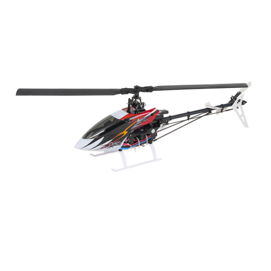
Specifications
Length:
Height:
Main Rotor Diameter:
Weight with Battery:
Main Motor:
Battery:
Transmitter:
On-Board Electronics:
Instruction Manual
20.25 in (514 mm)
7.25 in (184 mm)
22 in (588.8 mm)
4.8 oz (135g)
4200 KV brushless motor (installed)
3S 11.1V 1350 mAh 30c LiPo battery (included)
8-channel 2.4GHz (included)
25A brushless ESC , Flybarless unit w/Aegis Natural Flight Progression
(NFP) software and 6-axis Flight Stabilization System
receiver, 7.5 gram digital servos
(FSS),
2.4GHz
Advertisement
Table of Contents

Related Manuals for Ares OPTIM 300 CP


Summary of Contents for Ares OPTIM 300 CP
-
Page 1: Specifications
Instruction Manual Specifications Length: 20.25 in (514 mm) Height: 7.25 in (184 mm) Main Rotor Diameter: 22 in (588.8 mm) Weight with Battery: 4.8 oz (135g) Main Motor: 4200 KV brushless motor (installed) Battery: 3S 11.1V 1350 mAh 30c LiPo battery (included) Transmitter: 8-channel 2.4GHz (included) On-Board Electronics:... -
Page 2: Table Of Contents
Introduction ������������������������������������������������������������������������������������������������� 3 Safety Precautions ������������������������������������������������������������������������������������� 4 General Precautions ����������������������������������������������������������������������������������� 4 FCC Information ������������������������������������������������������������������������������������������ 5 Optim 300 CP Contents ������������������������������������������������������������������������������ 5 Needed to Complete ����������������������������������������������������������������������������������� 6 LiPo Battery Warnings �������������������������������������������������������������������������������� 6 Charging LiPo Battery ��������������������������������������������������������������������������������� 8 Flight Battery Installation ��������������������������������������������������������������������������� 9 Binding Procedure RTF ����������������������������������������������������������������������������... -
Page 3: Introduction
Introduction The Ares Advantage Optim 300 CP is the first RC helicopter in its size and class to assist pilots looking to progress from sport flying to 3D. The Aegis Natural Flight Progression (NFP) technology in the Optim 300 CP combines a state-of-the-art 6-axis sensor system with groundbreaking control software to create a RC heli training tool unlike any other. If you’re new to CP flight, your first step is to fly using the advanced 6-axis Flight Stabilization System (FSS) on the Optim 300 CP that allows you to fly basic sport maneuvers. All you have to do if you happen to get into trouble is let go of the sticks and the 300 CP will right itself and assist you in avoiding any potential crashes. When you’re ready to test your skills with 3D flight, the flip of a switch puts you in 3-axis agility mode. Pair this with the high-performance capabilities of the 300 CP heli, and you will be able to execute just about any 3D flight maneuver you can imagine. Better yet, if you lose control, flipping the switch back to the 6-axis Flight Stabilization System (FSS) automatically stabilizes the heli and helps you regain control and avoid a crash! Learning to fly inverted is the first big step to 3D flight and the Optim 300 CP makes taking the step to inverted flight easier than ever. The transmitter features a switch that, when turned on while in 6-axis FSS mode, automatically flips the Optim to stable inverted flight. While in stable inverted flight, you can familiarize yourself with how the heli responds differently to your controls with the assurance of knowing that all you need to do if you lose control is let go of the sticks and the Natural Flight Progression (NFP) technology assists you in going back to a stable inverted hover. And when you want to return to flying right side up again, it’s as easy as another flip of the switch! The Ares Advantage Optim 300 CP RTF comes with a 100% pre- assembled airframe, an 8-channel 2.4GHz transmitter, an 11.1V 1350mAh 30c LiPo battery, an 800mA DC charger with an AC adapter, and even the AA batteries to power up your transmitter. With nothing extra to buy to get in the air, you’ll be on your way to advancing your ... -
Page 4: Safety Precautions
Safety Precautions Failure to use this product in the intended manner as described in the following instruction can result in damage and/or personal injury. A Radio Controlled (RC) airplane/helicopter/quadcopter is not a toy! If misused it can cause serious bodily harm and damage to property. Keep items that could become entangled in the rotor blades away from the rotor blades, including loose clothing, tools, etc. Be especially sure to keep your hands, face and other parts of your body away from the rotor blades. As the user of this product you are solely and wholly responsible for operating it in a manner that does not endanger yourself and others or result in damage to the product or the property of others. This model is controlled by a radio signal that is subject to possible interference from a variety of sources outside your control. This interference ... -
Page 5: Fcc Information
The associated regulatory agencies of the following countries recognize the noted certifications for this product as authorized for sale and use: USA Optim 300 CP Contents Item Description Not Available Separately ... Optim 300 CP RTF Airframe AZSZ2302......Optim 300 CP RFR (Ready-For-Receiver) Heli AZSZ2381 ........MP8H 8-Channel Helicopter Transmitter, Mode 2 Not Available Separately .... AA Batteries (4pcs) AZSZ2384 ........800mA,3S,11.1V, DC Charger w/ AC adaptor AZSZ2373........1350mah, 30C,3S,11.1V LiPo Battery... -
Page 6: Needed To Complete
Needed to Complete The Optim 300 CP RTF includes everything needed to fly right out of the box. There’s nothing extra to buy or provide! LiPo Battery Warnings IMPORTANT NOTE: Lithium Polymer batteries are significantly more volatile than the alkaline, NiCd or NiMH batteries also used in RC applications. All instructions and warnings must be followed exactly to prevent property damage and/or personal injury as mishandling of LiPo batteries can result in fire. By handling, charging or using the included LiPo battery you assume all risks associated with LiPo batteries. If you do not agree with these conditions please return the complete product in new, unused condition to the place of purchase immediately. - Page 7 You MUST charge the LiPo battery in a safe area away from • flammable materials. NEVER charge the LiPo battery unattended at any time. When • charging the battery you should ALWAYS remain in constant observation to monitor the charging process and react immediate- ly to any potential problems that may occur. • After flying/discharging the battery you must allow it to cool to ambient/room temperature before recharging. To charge the LiPo battery you MUST use only the included LiPo • balance charger. Failure to do so may result in a fire causing property damage and/or personal injury. DO NOT use a NiCd or NiMH charger. If at any time during the charge or discharge process the battery • begins to balloon or swell, discontinue charging or discharging immediately. Quickly and safely disconnect the battery, then place it in a safe, open area away from flammable materials to observe for at least 15 minutes. Continuing to charge or dis- charge a battery that has begun to balloon or swell can result in a fire. A battery that has ballooned or swollen even a small amount must be removed from service completely. • Store the battery at room temperature, approximately 68–77° Fahrenheit (F), and in a dry area for best results. When transporting or temporarily storing the battery, the tempera- • ture range should be from approximately 40–100°F. Do not store the battery or model in a hot garage, car or direct sunlight whenev- er possible. If stored in a hot garage or car the battery can be damaged or even catch fire! •...
-
Page 8: Charging Lipo Battery
• In the case of the 3-Cell/1S 11.1V LiPo battery used to power the Optim 300 CP, you will not want to allow the battery to fall below 9.0V during flight. The ESC unit has low voltage cutoff (LVC) protection. However it • is not recommended to run the batteries down to this level on a regular basis. Charging LiPo Battery You MUST charge the included 1350mAh 3-Cell/3S 11.1V 30C LiPo Battery (AZSZ2373) using the included 800mA Charger w/AC adapter (AZSZ2384) or a suitably compatible LiPo battery charger. Charging the LiPo battery using a non-LiPo battery compatible charger (such as a NiCd or NiMH battery char- ger), or even a different LiPo battery charger with the incorrect settings, may result in damage to the battery or even fire resulting in property damage and/ or personal injury. To charge the flight battery, first plug the AC charge adapter into an AC out- let and then plug in the 800mA DC Balance Charger to the adapter. Plug the flight battery balance adapter into the balance charger. With the battery con- nected to the charger, both the red and green LED will light up. When the green LED goes out, leaving only the red LED lit, the charging is complete. -
Page 9: Flight Battery Installation
Flight Battery Installation Attach the battery to the airframe using the included hook and loop tape. Secure the battery with the the hook and loop strap. Once the battery is in place it can now be connected to the ESC battery plug. After plugging the battery in, set the helicopter on a level surface and allow the control system to initialize. Do not move the helicopter during this time. This typically takes a 5-10 seconds, when complete the servos will do a series of movements and control from the transmitter is established. ... -
Page 10: Binding Procedure Rtf
Binding Procedure RTF *Please note, for your safety, we recommend unplugging two of the motor wires anytime you will be working on the helicopter. Press and hold the button on the FBL unit while plugging in the flight battery. At this point you should see the LED on the receiver start to blink rapidly. With all the control switches set away from you turn on the transmitter and you should notice the LED on the receiver switch from blinking to solid. After the LED on the receiver is solid your helicopter is bound. To check this, you must first unplug the flight battery, then plug it back in. After the flight battery is plugged back in, wait for the helicopter to initialize and move the cyclic stick insuring you have movement on the swash plate. * If using a radio system other than the one included with the Optim 300CP RTF, Please refer to your radio systems manual for binding/ linking instructions. - Page 11 Assign the channels on the transmitter as follows: Channel 1: Throttle Channel 2: Aileron Channel 3: Elevator Channel 4: Rudder Channel 5: 6-axis stability ON/OFF switch Channel 6: Pitch Channel 7 (if available on transmitter): Norm/Inverted 6-axis switch Channel 8 (if available on transmitter): Tail gain If Channel 8 is not available, tail gain must be adjusted from Pot 3 on the FBL unit. If Channel 7 is not available, inverted 6-axis flight is not enabled. If the transmitter has programmable pitch/throttle curves available, we recommend a linear throttle curve and a linear pitch curve in Normal mode and 100% throttle with a linear pitch curve in Idle up Mode. The 6-axis stability On/Off switch should be set such that it outputs 100% when stability is turned on and -100% when stability is turned off. The Norm/Inverted 6-axis switch should be set such that it outputs -100% when non-inverted flight is selected and 100% when inverted flight is selected. Channel 8 should be set such that turning the knob from full counterclockwise to full clockwise (increasing gain) moves the output from -100% to 100%. If no knob/dial is available, the channel should be assigned a value of 0. BINDING If you are using the DSM2 protocol, you will need to place a Spektrum Bind Plug on the Input connector on the flybarless control unit before binding. If you are using the DSM-X protocol, this is not necessary. To enter bind mode, with the transmitter powered off, press and hold the button on the FBL unit while plugging in the battery. The receiver will start to blink rapidly to indicate that it is in bind mode. Then, power ...
- Page 12 on the transmitter in bind mode. The LED indicator on the receiver should become solid to indicate a solid link. You can now remove the Bind Plug (if connected). You will need to unplug the battery and plug it back in to re-initialize the system. You can also use another system to bind the receiver and transmitter and then install the already bound receiver into the helicopter. Instructions for use with Futaba® Transmitter and S.BUS Receiver To fly your Optim 300CP with a Futaba radio system, you will need a programmable Futaba compatible transmitter in helicopter mode with 6 channels or more and a Futaba compatible S.BUS receiver with 6 channels or more. The Optim 300CP supports both S-FHSS and FASST radio protocols. You will also need an adapter to connect the receiver to the S.BUS receiver (AZSZ2607). Connect the S.BUS adapter to the FBL unit using the AZSZ2607 S.BUS adapter cable. Make sure to use the correct polarity such that the brown GROUND wire on the adapter connects to the GROUND pin on the S.BUS adapter. DO NOT connect the servo outputs on the S.BUS receiver to the FBL unit, as doing so may damage the devices and will cause the helicopter to function incorrectly. Channel 1: Aileron Channel 2: Elevator Channel 3: Throttle Channel 4: Rudder...
-
Page 13: Transmitter Details
recommend a linear throttle curve in Normal mode and 100% throttle with a linear pitch curve in Idle up Mode. The 6-axis stability On/Off switch should be set such that it outputs 100% when stability is turned on, and -100% when stability is turned off. The Norm/Inverted 6-axis switch should be set such that it outputs 100% when non-inverted flight is selected and -100% when inverted flight is selected. Channel 8 should be set such that turning the knob from full counterclockwise to full clockwise moves the output from -100% to 100%. If no knob/dial is available, the channel should be assigned a value of 0. Transmitter Details Transmitter Voltage Display Tail Gain Throttle Hold Stable Mode ON/OFF Knob Dual Rates Idle Up Normal/Invert Throttle Curve Knob Left/Right Forward/Backward Throttle/Rudder Cyclic Stick Stick ON/OFF Switch Mechanical Trims Inactive (ALL) Channel Reversing... -
Page 14: Natural Flight Progression
Natural Flight Progression The Optim 300 CP offers two flight modes that enable pilots with varying degrees of experience to enjoy CP helicopter flight. The first mode is Stable Mode, which the pilot can turn on by setting the switch on the transmitter labeled “Stable Mode” to the “ON” position. In Stable Mode (6-Axis), the helicopter flies like a high performance tradi- tional CP helicopter, except that there is a stabilizing force which pulls it toward a neutral hover. As the helicopter moves further from neutral, this restoring or stabilizing force increases. Thus the helicopter can not become inverted when Stable Mode is active. When the cyclic stick is released, the helicopter quickly returns to neutral, making stable mode excellent for low- time pilots who are not entirely comfortable with traditional CP flight. The helicopter flies and feels like a CP, but it returns to a stable configuration when the sticks are released, thus making it easier to avoid crashes. Stable Mode functions in both normal and inverted flight. It is turned off by moving the switch on the transmitter to the back, or “OFF” position. When in “OFF”, the stabilization software is disabled and the helicopter responds quickly and nimbly to the pilot’s input. In this mode the helicopter does NOT return to neutral when the cyclic stick is released. If the pilot loses control in this mode, they can simply flip the Stable Mode switch on the transmitter back to the “ON” position, to help regain control of the helicopter. If stability mode is activated when the helicopter is inverted, the helicopter will return to upright stabilized flight. Dual Rate Switch The DUAL RATE switch adjusts the control sensitivity of the aileron/ elevator channels. We recommend that you start in low rates for your initial flights in stabilized mode and progress to high rates for 3D stunt flying. -
Page 15: Stability Control Switch
Stability Control Switch To put the helicopter into stable mode (6-axis), locate the Stable Mode Switch on the top left of the transmitter and flip it to the ON position. In this mode, the pilot will experience stable yet agile flight with the helicopter returning to level flight when the cyclic stick is returned to neutral. Idle Up Switch (Stunt) The Idle Up switch (Stunt/Normal) is used to set the throttle to full power in- dependent of the position of the throttle stick. When in idle up any throttle stick movement above mid point engages positive pitch on the main rotor, any stick movement below mid stick pro- duces negative pitch on the main rotor allowing you to fly inverted. For 3D flight, Idle Up should be engaged once you have taken off in Normal mode and established a stable hover. Use caution, engaging Idle Up brings the main rotor to full power! Throttle Hold Switch The Throttle Hold switch will shut ... -
Page 16: Throttle Curve Knob
Throttle Curve Knob The throttle curve can be adjusted when the helicopter is in normal mode. As the throttle curve is increased the throttle input will be more responsive and the head speed will be raised. We recommend that low time pilots keep the throttle curve near the middle until they become familiar with the helicopter. Invert Switch The Invert Switch must only be used in Idle Up (Stunt) mode when in 6-axis stability mode. When switched ON the helicopter will automatically flip to inverted stabilized flight allowing the pilot to gain experience in learning the flight controls when in inverted flight. Please note that when the helicopter flips to inverted the pilot will need to apply some additional negative pitch to maintain the inverted hover. A flip of the switch to OFF will flip the helicopter back into stabilized normal flight. Tail Gain Knob Tail gain is pre-set at the factory. It may need slight adjustment to suit your flying style. To set the gain, put the helicopter into a stable hover and increase the gain until a slight wag in the tail is evident. Back the gain down until the wag is gone. ... -
Page 17: Flight Controls
Flight Controls If you are unfamiliar with the flight controls on you Optim 300 CP please review them in the illustrations below. Descend... -
Page 18: Set Up Menu
Set Up Menu Your Optim 300CP FBL unit has set up configuration utility to make servicing your helicopter and getting it back in the air faster. Anytime you service your helicopter you should verify that the swashplate is perfectly level when the transmitter is in 3-axis mode and the helicopter is not moving. If this is not the case you can use the setup menu to set the helicopter up correctly. Enter the setup configuration menu by powering on the transmitter, plugging in the battery and rapidly pressing and holding the button on the top of the FBL unit. Release the button, and you will be in the first step of the configuration menu. 1. Servo Centering At this point, you will be able to move one of the cyclic servos up and down using the elevator stick. Once the elevator is centered such that the arm is horizontal, you can move to the next servo using the rudder stick. You will see a servo twitch to indicate which servo is currently being adjusted. Once again, you can adjust the servo center using the elevator stick until the servo arm is horizontal. Repeat for all servos and then press the button on the FBL unit to save your settings and move to the next configuration step. 2. Swashplate Leveling To level the swashplate, use the elevator and aileron input to move the swashplate to a perfectly level position. Then, press the button on the FBL unit to save your setting and advance to the next step. 3. Tail Servo Centering The third stage in the configuration menu is tail servo centering. In this stage, the tail servo will be set to a neutral position. Adjust the servo horn so that the tail pushrod ball is directly above the servo. Then, adjust the tail pushrod until the tail slider is in the middle of the tail shaft, with equal amounts of shaft visible on each side of the slider. When ready, press the FBL unit button to advance to the next step. 4. 6-Axis Calibration During 6-axis calibration mode, place the helicopter on a flat level surface. ... -
Page 19: Manual Trim Locks
Manual Trim Locks Your transmitter comes with trim locks installed to disable trimming. For high performance CP helicopters like the Optim 300 CP, if any trimming is required in 3-axis flight, it should be performed mechanically by adjusting the swashplate. For stabilized flight, trimming is performed using the FBL unit’s user interface. Therefore, the trim locks should not be removed from the transmitter for any reason. Trimming for 3-Axis Mode In 3-axis mode, the swashplate should be perfectly level when the cyclic controls are neutral and the helicopter is not moving. If the swashplate for some reason is far away from this setting, then the FBL system’s configuration menu (see appropriate section of the manual) can be used to reset the swashplate position. Minor adjustments can be made by adjusting the lengths of the swashplate pushrods. • If the helicopter tends to move forward in 3-axis flight, the front pushrods should be lengthened and the back pushrod should be shortened equal amounts to adjust the swashplate backward. • If the helicopter tends to move backward in 3-axis flight, the front pushrods should be shortened and the back pushrod should be extended equal amounts to adjust the swashplate forward. • If the helicopter tends to move left in 3-axis flight, the left servo pushrod should be extended and the right pushrod should be shortened an equal amount to adjust the swashplate right. •... -
Page 20: Vibration And 6-Axis Drift
Vibration and 6-Axis Drift In any helicopter, it is critical to reduce vibration as much as possible. The 6-axis NFP flybarless unit is attached to the helicopter using a revolutionary vibration isolation pad, which significantly reduces the vibration of the control unit. The NFP flybarless unit also features sophisticated vibration suppression software that reduces the effect of vibration to improve performance. If the helicopter is damaged in any way, vibrations may increase enough to degrade helicopter performance. In 3-axis mode, this is typically characterized by visible shakes in the helicopter. In 6-axis mode, the helicopter may become unable to correctly detect its orientation and begin to drift very fast or may even become impossible to fly. Therefore, it is absolutely critical to carefully inspect your helicopter after even a minor crash. Damage such as scuffed main blades or tail blades, bent feathering, main, or tail shafts, chipped gears are anything similar can be sufficient to degrade 6-axis performance. Improper blade tracking, wherein the two main blades are misaligned and do not rotate through the same plane, can cause degradation in 6-axis performance. Therefore, care must be taken to precisely track blades before flight. Parameter Menu The 300CP comes set up and ready for flight. If after your initial flight you want to make any trim or gain adjustments, follow these steps. With the helicopter on the ground and initialized, the throttle stick lowered all the way, and throttle hold activated, you can press and hold the button on the flybarless unit to enter the trim/gain menu. The trim/gain menu allows you to make changes and adjustments to improve your flight experience and includes the following features: 6-axis gain 1. 6-axis aileron trim 4. Rudder heading lock gain 2. 6-axis elevator trim You can progress through the modes by pressing the button on the face of the flybarless unit. The status LED will blink to indicate which menu item is currently active. There will be a series of blinks followed by a pause, after ... - Page 21 Mode/Bind Button LED Status Indicator Pot 1 Cyclic Gain Pot 2 Cyclic Feedforward Pot 3 Tail Gain Pot 2 Tail Dynamic 14 LED Trim Level Indicators 1. 6-axis Aileron Trim The Optim 300CP stabilized mode is designed to give the pilot maximum stability and minimize drift in wind-free conditions with cyclic inputs neutral. While there will always be some drift, if the helicopter tends to consistently move in one direction, a 6-axis trim mode is provided to reduce this drift. To adjust this trim, navigate the trim/gain menu until you are in aileron gain trim mode. Trim can be added by moving the aileron stick left or right in aileron trim mode. You will notice the number of illuminated LEDs decrease (left trim added) or increase (right trim added). A blinking LED indicates a half trim step. At the neutral trim setting, there will be 7 fully lit LEDs.Once you have made the desired change in aileron trim, press the button on the FBL unit again to save your settings and proceed to elevator trim mode.
-
Page 22: Tuning Cyclic In 3-Axis
changes, press the button on the flybarless unit to progress to the heading lock gain mode. 4. Heading-Lock Gain Mode When you enter the heading lock gain mode, you will see the status LED blinking pattern change to indicate that you have moved into this mode. Here, you will be able to adjust the heading lock gain. Moving the elevator stick upward will increase the gain, while moving it downward will decrease the gain. The LED display will reflect this change. When you have made the desired change, press the button on the flybarless unit again to save your settings and return to normal operation. Heading lock affects how strongly the rudder will act to maintain the commanded position. This includes the scenario where the rudder stick is neutral, and the commanded speed is 0. With low heading lock gain, the tail may incur unwanted drift. With excessive heading lock gain, the tail will move back and forth or “hunt/wag”, and the tail will not stop crisply when commanded to do so. We recommend that the user sets this gain as high as possible without hunting or wagging. Please note that heading lock is turned completely off when the heading lock gain is set to 0. We do not recommend flying in this mode, as the rudder will drift constantly. However, this mode can be used to correct the length of the tail servo pushrod. To make this correction, set the heading lock gain to zero and hover the helicopter. Observe which direction the rudder drifts. Then, land the helicopter and shorten or lengthen the tail pushrod accordingly. Repeat this process until rudder drift is minimized. Once this is done, make sure to increase the heading lock gain before resuming normal flight. Tuning Cyclic in 3-Axis Tuning Cyclic response for 3-Axis mode For a positive first flight experience in 3-axis mode, the Optim 300CP is shipped with conservative gain settings to ensure a stable and enjoyable ... -
Page 23: Fine Tuning Rudder
may respond slowly to disturbances and may not hold its orientation very stably. The pilot may feel that the helicopter is “loose” in this situation. The second potentiometer, Pot 2, is for adjusting the elevator and aileron for forward flight (feedforward). Increasing this setting by turning Pot 2 clockwise will increase the response of the helicopter to aileron and elevator inputs. If this setting is set too high, the helicopter might feel jumpy, and, if it is set too low, the helicopter may feel sluggish in its cyclic response. Fine Tuning Rudder Tuning Rudder for Optimal Performance There are three adjustments possible for the rudder or tail. The first is tail gain, which can be adjusted either on the transmitter for radios with 8 or more channels or using Pot 3 when using transmitters with 7 or fewer channels. For example, on the provided 8-channel transmitter, tail gain can this be increased by turning the tail gain knob clockwise. Increasing gain will make the tail control stiffer. However, increasing the gain too much may cause the tail to oscillate or “hunt.” The second tail adjustment is Tail Dynamic, which is changed using Pot 4. Turning this pot clockwise will increase tail dynamic. Increasing tail dynamic may improve tail acceleration and deceleration, helping the tail respond more rapidly to your input. However, increasing tail dynamic too much may cause a rapid vibration in the tail, which may damage the tail servo. In general, it is beneficial to use the lowest tail dynamic setting for which good tail performance can be achieved. The third tail adjustment is heading lock gain, which is available in the parameter menu. See description on page 22 of this manual. The flybarless unit should fly well out of the box, but additional fine- tuning may be desirable to achieve optimal performance. We recommend that the pilot increases tail gain until the tail starts to oscillate and then decreases it until the tail is steady. Then, tail dynamic can be added to make stops sharper. If the tail starts to oscillate quickly after a sharp stop, the tail dynamic is too high. Finally, the pilot can increase the heading lock gain until the tail starts to “hunt” back and forth, and then decrease ... -
Page 24: Flight Progression
If your helicopter vibrates or oscillates, immediately land it and adjust gain settings to avoid servo failure. Flight Progression The Ares Optim 300 CP with NFP (Natural Flight Progression) technology is designed to assist you in progressing through and mastering the skills required to fly a 3D capable helicopter. By following these steps you will make the quickest progress with the least amount of down time and repair. IMPORTANT NOTE:... - Page 25 IMPORTANT NOTE: During the aerobatic and inverted flight steps you will be turning the Idle Up switch to the STUNT position. WARNING! WARNING! Switching the Idle Up to STUNT brings the main rotor to full Switching the Idle Up to STUNT brings the main rotor to throttle independent of the throttle stick position full throttle independent of the throttle stick position.
-
Page 26: Post Crash Inspection
During the learning process some crashes are inevietable. It is critical to the flight performance of the helicopter that a thorough post crash inspection is carried out. Look for any broken or damaged parts. Not inspecting the helicopter after a crash will result in poor flight characteristics and possibly further damage to the helicopter. Although the whole helicopter should be examined, some of the more common parts to sustain damage in a crash are as follows: • Main gear • Main shaft • Main Blades • Feathering shaft • Landing gear • Servo • Tail boom • Tail shaft Please check out our videos! Flying videos Product set-up videos Maintenance and Repair videos www.ares-rc.com... -
Page 27: Trouble Shooting Guide
Trouble Shooting Guide... -
Page 28: Exploded View
Exploded View... -
Page 29: Parts Legend
Parts Legend Main Blade Set AZSZ2329 Bearing Set 3x6x2.2 (2) AZSZ2340 Main Rotor Grip Set AZSZ2327 Main Rotor Blade Screw/Nut AZSZ2341 Main Grip Bearing Set (2) AZSZ2342 Dampers (4) AZSZ2343 Feathering Shaft (2) AZSZ2344 Head Block AZSZ2345 Follower Arms AZSZ2346 Linkage Set AZSZ2347 Swashplate AZSZ2323 Main Shaft (2) AZSZ2348 Bearing Set 2x5x2.5 (2) AZSZ2349 Tail Drive gear (2) AZSZ2350 Gear Hub AZSZ2351 Bearing Set 4x8x3 AZSZ2352 Motor Mount Set AZSZ2353 Canopy Mounts (2) AZSZ2354 Anti-Rotation Bracket AZSZ2355 Servo Arm Set AZSZ2356 Landing Gear Set... - Page 30 Tail push rod Guide Set AZSZ2362 Tail Servo Mount AZSZ2363 Tail pushrod (2) AZSZ2364 Tail Stabilizer/fin set AZSZ2338 Horizontal Fin Mount AZSZ2365 Tail Case AZSZ2366 Tail Rotor Pitch Arm Set AZSZ2387 Bearing Set 3x7x3 (2) AZSZ2367 Tail Rotor Shaft/Pulley (2) AZSZ2368 Tail Pitch Control Slider AZSZ2369 Tail Blade Set AZSZ2339 Tail Hub AZSZ2370 Main Gear (2) AZSZ2319 Canopy AZSZ2371 Complete Hardware set AZSZ2331 Tail Thrust bearing Set AZSZ2388 3x6x2.5(2) 1350,mah,30c,3s,11.1 AZSZ2373 Battery Pinion Gear AZSZ2374 25A Speed control AZSZ2375 4200KV Brushless motor AZSZ2376 Blade Holder...
-
Page 31: Upgrade Parts List
Upgrade Parts List 6 Channel, 2.4G, FHSS AZSZ2386 Receiver AZSZ2383C Servo Gears/Cyclic AZSZ2383T Servo Gears/Tail AZSZ2385 Vibration Isolation Pad AZSZ2323AL Aluminum Swash Plate Aluminum Main Rotor Blade AZSZ2327AL Grip Set AZSZ2329W Wood Main Blade Set AZSZ2329CF Carbon Fiber Main Blade Set Carbon Fiber Tail Stabilizer/ AZSZ2338CF Fin Set AZSZ2339CF Carbon Fiber Tail Blade Set AZSZ2345AL Aluminum Head Block AZSZ2346AL Aluminum Follower Arms Aluminum Anti-Rotation AZSZ2355AL Bracket Aluminum tail Boom Support AZSZ2360AL AZSZ2361CF Carbon Fiber Tail Boom Aluminum Tail Rotor Pitch AZSZ2387AL Arm Set AZSZ2363AL Aluminum Tail Servo Mount Aluminum Horizontal Fin ... -
Page 32: Warranty Information
AZSZ2371B Canopy/Black AZSZ2371Y Canopy/Yellow AZSZ2389 Futaba SBUS Adapter AZSZ2337AL Aluminum Tail Blade Grip Mounting Access, AZSZ2399 Screwdriver & Wrench Warranty Information 30-Day Limited Warranty Term Period: We warranty that the Product(s) purchased (the “Product”) will be free from defects in materials and work m anship when the product is new (before being used) for the limited warranty term period, 30 days, from the date of purchase by the Purchaser. If you believe a defect in material, workmanship, etc. was not apparent when the Product was new and only became evident after the Product was used, take the following steps. If you purchased the Product at a HobbyTown store, please contact your local HobbyTown store for warranty support and/or service. If you purchased the Product from the Firelands website, use the contact information found under the Support heading to contact Firelands directly. If you contact Firelands, you may be asked to send the product to Firelands, at your cost, for inspection. Provided the warranty conditions have been met within the warranty term period, the components that are found to be defective, incorrectly manufactured or assembled may be repaired or replaced, at the sole discretion of Firelands. Your warranty item will be returned to you at Firelands’ expense. In the event your product needs repair or a replacement part that is not covered by this warranty, your local HobbyTown store or Firelands can assist you with support and in obtaining the genuine replacement parts to repair your Prod u ct. Firelands will charge $40.00 per hour plus the cost of replace- ment parts to service your vehicle if after contacting you, you so authorize such ... - Page 33 NOTES...
- Page 34 © 2014...
Need help?
Do you have a question about the OPTIM 300 CP and is the answer not in the manual?
Questions and answers