Ares Gamma 370 Pro Instruction Manual
Hide thumbs
Also See for Gamma 370 Pro:
- Instruction manual (56 pages) ,
- Instruction manual (56 pages) ,
- Instruction manual (40 pages)
Table of Contents
Advertisement
Quick Links
Specifications
Wingspan:
Length:
Weight with Battery:
Battery:
Charger:
Transmitter and Receiver:
On‐Board Electronics:
37.0 in (940mm)
30.6 in (775mm)
16.0‐17.5 oz (455‐495 g)
800‐1300mAh 2S 7.4V or 3S 11.1V LiPo (required)
2S 7.4V or 3S 11.1V LiPo Balancing (required)
4+ channel (required)
Brushless motor, ESC and 3 servos (installed)
Instruction Manual
1
Advertisement
Table of Contents

Related Manuals for Ares Gamma 370 Pro


Summary of Contents for Ares Gamma 370 Pro
-
Page 1: Instruction Manual
Instruction Manual Specifications Wingspan: 37.0 in (940mm) Length: 30.6 in (775mm) Weight with Battery: 16.0‐17.5 oz (455‐495 g) Battery: 800‐1300mAh 2S 7.4V or 3S 11.1V LiPo (required) Charger: 2S 7.4V or 3S 11.1V LiPo Balancing (required) Transmitter and Receiver: 4+ channel (required) ... -
Page 2: Table Of Contents
Table of Contents Specifications ............................ 1 Notes ................................. 3 Introduction .............................. 4 Safety Precautions and Warnings ...................... 4 FCC Information ............................ 5 Required to Complete.......................... 6 Installing the Receiver .......................... 6 Assembling the Wing .......................... 7 Installing the Horizontal and Vertical Tails ..................... 12 Installing the Landing Gear ........................ 13 Installing the LiPo Flight Battery ...................... 14 Centering the Control Surfaces ...................... 16 Installing the Propeller/Optional‐Use Prop Saver .................. 18 Attaching the Wing .......................... 23 ... -
Page 3: Notes
Notes ____________________________________________________________________________ ____________________________________________________________________________ ____________________________________________________________________________ ____________________________________________________________________________ ____________________________________________________________________________ ____________________________________________________________________________ ____________________________________________________________________________ ____________________________________________________________________________ ____________________________________________________________________________ ____________________________________________________________________________ ____________________________________________________________________________ ____________________________________________________________________________ ____________________________________________________________________________ ____________________________________________________________________________ ____________________________________________________________________________ ____________________________________________________________________________ ____________________________________________________________________________ ____________________________________________________________________________ ____________________________________________________________________________ ____________________________________________________________________________ ____________________________________________________________________________ ____________________________________________________________________________ ____________________________________________________________________________ ____________________________________________________________________________ ____________________________________________________________________________ ____________________________________________________________________________ ____________________________________________________________________________ ____________________________________________________________________________ ____________________________________________________________________________ ____________________________________________________________________________ ____________________________________________________________________________ ____________________________________________________________________________ ____________________________________________________________________________ ____________________________________________________________________________ ____________________________________________________________________________ ____________________________________________________________________________ ____________________________________________________________________________ ____________________________________________________________________________ ____________________________________________________________________________ 3 ... -
Page 4: Introduction
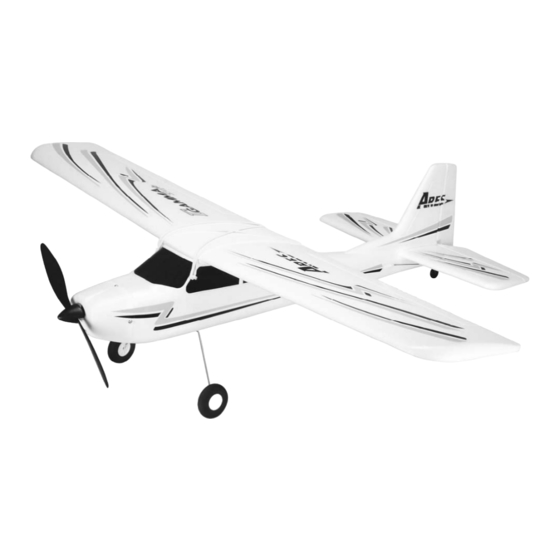
Introduction The Ares™ [air‐eez] Gamma 370 Pro offers the stability and durability of the original Gamma 370 while also delivering full 4‐channel control and aerobatic capability sport flyers will enjoy. The advanced EPO foam airframe design is not only lightweight, durable and easy to repair, it also arrives factory‐assembled and nearly ready‐to‐fly right out of the box so you can be flying at a local park, schoolyard or flying field in almost no time at all. The Gamma 370 Pro is RFR (Ready‐For‐Receiver) and includes a factory‐installed 370 brushless motor, 18‐amp brushless ESC and three 9‐gram sub‐micro servos. It’s ready for you to install a 4+ channel receiver compatible with your favorite transmitter and includes two propeller options for use with 2S 7.4V or 3S 11.1V 800‐1300mAh LiPo batteries. Best of all it’s available at a price that offers unbelievable value and makes it hard for almost any pilot to resist! The factory‐installed brushless power system is quiet, efficient and powerful delivering great performance and long flight times with 2S 7.4V and unlimited vertical performance with 3S 11.1V LiPo batteries. Coupled to smooth and precise aileron, elevator and rudder controls the Gamma 370 Pro is capable of all basic and even advanced 4‐channel aerobatics including point rolls, rolling circles, knife edge and more! And although the Gamma 370 Pro is nearly ready‐to‐fly right out the box please take the time to read through this manual for information on assembly, control checks and more before making your first flight. Please also visit our web site at www.Ares‐RC.com for additional information including product updates, bulletins, videos and more. Safety Precautions and Warnings Failure to use this product in the intended manner as described in the following instructions can result in damage and/or personal injury. A Radio Controlled (RC) airplane/helicopter is not a toy! If misused it can cause serious bodily harm and damage to property. Keep items that could become entangled in the propeller/rotor blades away from the ... -
Page 5: Fcc Information
This model is controlled by a radio signal that is subject to possible interference from a variety of sources outside your control. This interference can cause momentary loss of control so it is advisable to always keep a safe distance from objects and people in all directions around your model as this will help to avoid collisions and/or injury. • Never operate your model if the voltage of the batteries in the transmitter is too low. • Always operate your model in an open area away from obstacles, people, vehicles, buildings, etc. • Carefully follow the directions and warnings for this and any optional support equipment (chargers, rechargeable batteries, etc.). • Keep all chemicals, small parts and all electronic components out of the reach of children. • Moisture causes damage to electronic components. Avoid water exposure to all electronic components, parts, etc. not specifically designed and protected for use in water. • Never lick or place any portion of your model in your mouth as it could cause serious injury or even death. FCC Information This device complies with part 15 of the FCC rules. Operation is subject to the following two conditions: (1) This device may not cause harmful interference, and (2) this device must accept any interference received, including interference that may cause undesired operation. Caution: Changes or modifications not expressly approved by the party responsible for compliance could void the user’s authority to operate the equipment. This product contains a radio transmitter with wireless technology which has been tested and found to be compliant with the applicable regulations governing a radio transmitter in the 2.400GHz to 2.4835GHz frequency range. The associated regulatory agencies of the following countries recognize the noted ... -
Page 6: Required To Complete
Required to Complete The Gamma 370 Pro is RFR (Ready‐For‐Receiver) and requires the following items: 4+ channel transmitter (with suitable range for a ‘park flyer’ class model) 4+ channel receiver (compatible with the transmitter that will be used) 2‐Cell/2S 7.4V or 3‐Cell/3S 11.1V 800–1300mAh LiPo battery (15+C continuous discharge rate capable) LiPo battery charger (compatible with the battery that will be used) Installing the Receiver Use the included adhesive‐backed ‘hook‐and‐loop’ material to install the receiver (not included) compatible with the transmitter you’ve chosen to use. Install the receiver on the side of the fuselage opposite of the ESC. Plug the 3‐wire lead from the ESC into the ‘throttle’ channel, the elevator servo lead into the ‘elevator’ channel and the rudder servo lead into the ‘rudder’ channel on the receiver. NOTE: It’s important to ensure correct polarity when plugging the leads/connectors into the receiver. Refer to the markings on the receiver (or the instruction manual for the receiver) to identify which pins accept the black color (negative/ground), red color (positive) and white color (signal) wire leads. Also, depending on the make/model of receiver it may be necessary to slightly ‘bevel’ the edges of the black color connectors so they fit easily into the case of the receiver. We recommend using a small file or sanding block and EXTREME CARE to bevel the appropriate edges of the connectors as needed. 6 ... -
Page 7: Assembling The Wing
Assembling the Wing Parts/Tools Required: Left and right wing panels Thin two‐sided tape (optional) Plastic wing cover 5–15 minute epoxy (optional) To assemble the wing start by sliding the plywood ‘joiner’ that extends out of the right wing panel into the corresponding slot in the left wing panel. Carefully slide the panels together until they meet. OPTIONAL: For a more secure wing joint you can use thin two‐sided tape or 5–15 minute epoxy between the panels. Thick cyanoacrylate (CA) glue may also be used keeping in mind that the use of glue/epoxy will result in a more ‘permanent’ wing joint. Also, it’s important to ensure that the top and bottom sides of the wing panels are aligned properly, especially near the leading (front) and trailing (rear) edges, when joining the panels with tape or glue/epoxy. NOTE: Due to slight variations in the production of related parts it’s possible that the leading (front) and trailing (rear) edges of both wing panels will not align exactly when the panels are slid together. This OK and should have no discernible impact on the flight performance/characteristics of the model. After sliding/joining the two wing panels together locate the plastic ‘wing cover’. This cover helps protect the top of the wing from the rubber bands used to attach it to the fuselage while also providing additional support for the wing joint. Before removing the backing material on the tape used to secure the cover to the wing check the fit of the cover on the wing. Line up the trailing (rear) edge of the cover with the trailing edge of the wing while also ‘centering’ the cover over the joint between the wing panels 7 ... - Page 8 After confirming the cover fits correctly remove the backing material to expose the tape. Then, very carefully line up the trailing edge of the cover with the trailing edge of the wing and center the cover before pressing it down against the wing panels. Start from the trailing edge of the wing and slowly press the cover down with light pressure so it fits against the wing as closely as possible until you reach the leading (front) edge. Apply only light pressure so you can possibly remove and reinstall the cover if the fit/alignment is not correct. Then, after confirming the fit and alignment are good, apply more pressure to better secure the cover to the wing. NOTE: In some cases it may not be possible for all edges of the cover to fit flush against the surface of the wing. This is not typically a problem as the rubber bands used to attach the wing to the fuselage will help hold the edges of the cover in place. However, depending on the fit of some parts it may be helpful to apply transparent ‘packing’ tape and/or cyanoacrylate (CA) glue (we recommend Medium/Gap‐Filling or Thick viscosity) to better secure the edges. Keep in mind that the use of glue will result in a more ‘permanent’ installation of the wing cover. Next, select a two‐sided servo arm that has holes at least 7/16”–1/2” (11–13mm) from the center on either side. Check to see if the ‘Z‐bends’ of the pushrods fit/pass through the existing holes in the servo arm. If not USE EXTMREME CARE AND A HOBBY KNIFE WITH A SHARP NO.11 BLADE, OR A PIN VISE/DRILL WITH A 3/64” (1.2mm) DRILL BIT, TO VERY CAREFULLY ENLARGE THE HOLES IN THE POSITIONS YOU PLAN TO USE JUST ENOUGH SO THE Z‐BENDS CAN PASS THROUGH THEM. It’s very important that you DO NOT enlarge the holes more than necessary otherwise the pushrods will be too loose in the holes potentially resulting in ‘slop/play’ that may make it difficult to properly trim and control the ailerons in flight. Of course it’s also important that the pushrods are not installed too tightly in the holes (the pushrods should rotate freely but without slop/play). 8 ...
- Page 9 After selecting and preparing a suitable servo arm, plug the lead/connector from the aileron servo into the aileron channel of your receiver. NOTE: You can install an optional ‘servo extension’ between the receiver and aileron servo lead to make it easier to connect/disconnect the servo now and when installing/removing the wing in the future. Turn the transmitter on, center the aileron channel trim and connect a suitable LiPo battery to the ESC to power on the receiver and servos. Check to be sure the aileron servo responds to left and right control inputs correctly then center the right‐hand stick. IMPORTANT NOTE: Before installing the servo arm on the servo you should set the ‘servo reversing’ for the aileron channel as necessary to ensure the ailerons/aileron servo are responding correctly to control stick movements (as shown in the ‘Flight Controls and Trimming’ section of this manual). With the aileron stick and trim centered the servo should also be centered. Now install the selected servo arm on the output shaft of the servo so it’s as close to perpendicular to the servo case as possible. It’s OK if the arm cannot be positioned exactly perpendicular to the case as long as it’s close. However, if the arm is more than 5–10 degrees away from perpendicular we suggest rotating the arm approximately 180‐degrees and/or checking other suitable servo arms until you find the one that fits with the best alignment overall. After installing the servo arm on the output shaft in the position with the best possible alignment use one of the included 2 x 6mm ‘button’ (small) head screws to secure the servo arm to the output shaft (do not over‐ tighten the screw!). 9 ...
- Page 10 With the servo arm installed and the aileron stick and trim still centered carefully spread open each ‘clevis’ (the white plastic part installed on the threaded end of the metal pushrod) so you can insert the pin in the hole on each control horn/bracket attached to the ‘aileron torque rods’ installed in the wing. It may be helpful to insert a flat blade screwdriver (not included) into the clevis then to carefully ‘twist’ it until it disengages the pin from the hole in the clevis. Also, it is not necessary to ‘snap’ the clevis back together until the centering adjustments are complete. After connecting the clevises to the control horns/brackets view the trailing (rear) edge of the ailerons and wing from directly behind. The trailing edges of the ailerons should be ‘in line’ with the trailing edges of the wing when ailerons are properly ‘centered’. However, if the ailerons are ‘off center’ you can adjust the length/position of the pushrods/clevises as needed. If either aileron is ‘above’ center carefully remove the clevis from the control horn/bracket and screw it ‘in’ (clockwise) one half to one full turn then insert the pin back into the control horn/bracket. Or, if either aileron is ‘below’ center screw the clevis ‘out’ (counter‐clockwise) one half to one full turn then insert the pin back into the control horn/bracket. View the trailing edges of the ailerons and wing from directly behind again and continue adjusting the length/position of the pushrod/clevis until both ailerons are centered appropriately. NOTE: In some cases it may not be possible to exactly center the inboard and outboard portions of an aileron relative to the trailing edges of the wing. If you find this to be the case simply adjust the length/position of the pushrod/clevis to ‘split the difference’ between the inboard and outboard portions relative to the trailing edges of the wing. 10 ...
- Page 11 NOTE: You should always rotate the clevis until the pin is perpendicular with the control horn to ensure the pin is not under any excessive load/pressure when inserted in the hole and during operation. In some cases it may not be possible to ‘exactly’ center the surface mechanically while properly aligning the pin. In these cases be sure the pin is properly aligned then adjust the position of the trim (or sub‐trim) slightly as needed. Also, it will likely be necessary to make further adjustments to the trim setting during flight as most surfaces do not end up in exactly the centered position when an airplane is trimmed properly for actual flight (but ‘centered’ is still the best starting point). Also, we strongly recommend installing the included ‘clevis keepers’ (the clear rubber tubing sections) to provide added security for the clevises. Typically you can carefully slide the keepers over the clevises when they are not connected to the control horn. Then, after connecting the clevis to the control horn and ‘snapping’ the clevis together you can slide the keepers into a position that does not allow them to ‘bind’ against the control horn/bracket during movement of the surface. The wing is now assembled and ready to attach to the fuselage in a later step. 11 ...
-
Page 12: Installing The Horizontal And Vertical Tails
Installing the Horizontal and Vertical Tails Parts/Tools Required: Fuselage 2 x 8mm ‘button’ (small) head screw; 2pcs Horizontal and vertical tails 2 x 8mm ‘pan’ (large) head screw; 1pc Plastic tail mount Phillips screwdriver To install the horizontal and vertical tails start by aligning the ‘posts’ extending from the bottom of the vertical tail with the small holes located on the centerline of the horizontal tail. Carefully slide the posts through the holes without damaging the foam so the horizontal and vertical tails are ‘press‐fit’ together. Next, carefully slide the forward section of the vertical tail into the corresponding recess on the fuselage then lower the tail section into place on the fuselage so the small ‘tabs’ on the bottom of the horizontal tail align and fit into the corresponding recesses in the fuselage. Now the entire tail section should be ‘press‐fit’ to the fuselage. 12 ... -
Page 13: Installing The Landing Gear
Before installing the plastic tail mount be sure to align and place the tail wheel bracket/mount into the corresponding recess in the bottom of the fuselage. Then, carefully slide the posts extending from the tail mount into the holes in the fuselage. The posts extending from the tail mount must engage the posts that extend from the bottom of the vertical tail while also ‘capturing’ the tabs on the tail wheel bracket/mount. Take your time and carefully adjust the position of the tail section, tail wheel bracket/mount and tail mount until both posts and the tail wheel bracket/mount engage properly. When engaged properly the tail mount should fit almost flush against the bottom of the fuselage. Now you can slide the two 2 x 8mm ‘button’ (small) head screws into the recessed openings in the mount and tighten them securely. Be careful when tightening these screws because tightening them too much can strip/break the plastic posts and/or damage the tails/fuselage. To complete the installation use the remaining 2 x 8mm ‘pan’ (large) head screw to secure the tail wheel bracket/mount in place. Installing the Landing Gear Parts/Tools Required: Main Landing Gear Assembly 2 x 8mm ‘button’ (small) head screw; 2pcs Plastic Landing Gear Cover Phillips screwdriver The main landing gear is installed in the slot/opening located in the ‘Landing Gear Mount/Battery Hatch’ on the bottom of the fuselage. Use moderate pressure to ‘squeeze’ the landing gear legs together slightly then slide the landing gear into the slot (you can also remove the landing gear by doing the same). Be sure the landing gear is installed so it angles forward (toward the front of the airplane) when viewing the airplane directly from the side. 13 ... -
Page 14: Installing The Lipo Flight Battery
Slide the plastic landing gear cover into the slot/over the landing gear and carefully align the small pins on the cover with the holes in the mount. Press the cover into place so it’s approximately flush with the mount/hatch then use two 2 x 8mm ‘button’ (small) head screws to secure the cover and landing gear in place. Installing the LiPo Flight Battery IMPORTANT NOTE: You must ALWAYS turn the transmitter on first AND have the throttle stick in the lowest possible position BEFORE connecting/installing the LiPo flight battery. And before proceeding with the following steps, please be sure the transmitter is powered on and the throttle stick is in the lowest possible position. After selecting a suitable 2‐Cell/2S 7.4V or 3‐Cell/3S 11.1V 800–1300mAh LiPo battery and charging it fully it’s ready to be installed in the airplane. To access the battery compartment on the bottom of the airplane, rotate the two latches until they’re out of the way of the hatch cover then remove the cover. The LiPo flight battery will be secured inside the airplane using ‘hook‐and‐loop’ material. Use the included adhesive‐backed hook‐and‐loop material and apply the appropriate side inside the battery compartment and/or on the battery. 14 ... - Page 15 IMPORTANT NOTE: The factory‐installed ESC (Electronic Speed Control) is equipped with a ‘Tamiya‐style male’ connector. If your chosen LiPo battery is not equipped with a suitable Tamiya‐style female mating connector a number of pre‐made adapters from ‘Tamiya female’ to Deans (Ultra Plug), EC3, EC2 and other connectors are available. Check your favorite local store for availability of a suitable adapter or you can remove the Tamiya male connector from the leads of the ESC and replace it with a connector of your choice. Before installing the battery in the airplane you’ll need to connect it to the ESC. YOU MUST BE CAREFUL TO ENSURE PROPER POLARITY BEFORE CONNECTING THE BATTERY TO THE ESC. By orienting/aligning the wire leads of the battery and ESC so they’re ‘red to red’ and ‘black to black’ you’ll be able to make the connection with correct polarity. After the LiPo battery is connected to the ESC you can insert it into the battery compartment then secure it with the hook‐and‐loop material. Carefully ‘tuck’ the wire leads and connectors inside the compartment ensuring they do not damage the battery or foam airframe while also allowing the hatch cover to be installed over the compartment opening. When the hatch cover is properly aligned and installed rotate the two latches until they secure the cover in place. To remove the LiPo flight battery first remove the hatch cover and pull the wire leads and connectors out of the battery compartment. Then, carefully pull the battery out of the compartment by separating the hook‐and‐loop material mounted inside the fuselage and on the battery. Disconnect the battery from the ESC and DO NOT power off the transmitter until the LiPo flight battery is removed from the airplane and disconnected from the ESC. REMEMBER: The transmitter is always ON FIRST and always OFF LAST! 15 ...
-
Page 16: Centering The Control Surfaces
Centering the Control Surfaces With the transmitter turned on and the LiPo flight battery connected to the ESC (and installed in the battery compartment) it’s now possible to connect the pushrods to the rudder and elevator control surfaces and to ‘center’ the surfaces accordingly. First, be sure to center the elevator and rudder channel trims on your transmitter. With the trims centered carefully spread open each ‘clevis’ (the white color plastic part installed on the threaded end of the metal pushrod) so you can insert the pin in the OUTERMOST (for less control surface travel/throw) or SECOND OUTERMOST (for more control surface travel/throw) hole on each control horn. It may be helpful to insert a flat blade screwdriver (not included) into the clevis then to carefully ‘twist’ it until it disengages the pin from the hole in the clevis. Also, it is not necessary to ‘snap’ the clevis back together until the centering adjustments are complete. After connecting the clevises to the control horns view the vertical tail and rudder from directly above. The rudder should be ‘in line’ with the vertical tail when it’s properly ‘centered’. However, if the rudder is angled off to the right or left you can adjust the length/position of the pushrod/clevis so the surface is centered ‘mechanically’ while the rudder channel trim is centered. 16 ... - Page 17 If the rudder is angled off to the left carefully remove the clevis from the control horn and screw it ‘in’ (clockwise) one half to one full turn then insert the pin back into the outermost or second outermost hole in the control horn. Or, if the rudder is angled off to the right carefully remove the clevis from the control horn and screw it ‘out’ (counter‐clockwise) one half to one full turn then insert the pin back into the outermost or second outermost hole in the control horn. View the vertical tail and rudder from directly above again and continue adjusting the length/position of the pushrod/clevis until the rudder is centered appropriately. NOTE: You should always rotate the clevis until the pin is perpendicular with the control horn to ensure the pin is not under any excessive load/pressure when inserted in the hole and during operation. In some cases it may not be possible to ‘exactly’ center the surface mechanically while properly aligning the pin. In these cases be sure the pin is properly aligned then adjust the position of the trim lever slightly as needed. Also, it will likely be necessary to make further adjustments to the position of the trim lever during flight as most surfaces do not end up in exactly the centered position when an airplane is trimmed properly for actual flight (but ‘centered’ is still the best starting point). Follow the same steps outlined for centering the rudder to center the elevator as well. Also, we strongly recommend installing the included ‘clevis keepers’ to provide added security for the clevises. Typically you can slide the keeper over the clevis when it’s not connected to the control horn. Then, after connecting the clevis to the control horn and ‘snapping’ the clevis together you can slide the keeper into a position that does not allow it to ‘bind’ against the control horn during movement of the surface. 17 ...
-
Page 18: Installing The Propeller/Optional-Use Prop Saver
Installing the Propeller/Optional-Use Prop Saver IMPORTANT NOTE: Before installing the propeller you MUST disconnect the battery from the ESC. Failure to do so can result in serious bodily harm and/or damage to property! There are two options available for installing the propeller on the Gamma 370 Pro. The first option is for ‘standard’ installation of the propeller and spinner while the second option is for installation of the ‘prop saver’. We recommend installing the prop saver if flying over rough surfaces and/or long grass as it can help protect the propeller, motor shaft and ESC from damage during some less than perfect takeoffs and landings. Also, two different size propeller options are included with the Gamma 370 Pro. We recommend installing the (larger diameter) 9 x 7 Slow Flyer Propeller (AZSP0970SF) for use with 2‐cell/2S 7.4V LiPo batteries, or the (smaller diameter) 8 x 6 Slow Flyer Propeller (AZSP0860SF) for use with 3‐cell/3S 11.1V LiPo batteries. IMPORTANT NOTE: The propeller must be installed in the correct direction in order for the airplane to fly! The front of the propeller is the side that is slightly curved/rounded ‘outward’. This side of the propeller must ALWAYS face forward on the Gamma 370 Pro for proper operation and performance. 18 ... - Page 19 Standard Installation Parts/Tools Required: Propeller (8x6 or 9x7) 3mm flat washer; 1pc Rubber Spinner Pliers, adjustable wrench or 5.5mm socket/wrench 3mm hex ‘lock’ nut; 2pcs To install the propeller start by threading the first (rear) 3mm hex ‘lock’ nut onto the threaded portion of the motor shaft, with the nylon insert/’lock’ oriented toward the BACK of the airplane, until it stops at the end of the threads. Tighten this nut in place (do not over‐tighten!) then install the propeller on the shaft and rotate it as necessary until it lines up with, slides over and fully ‘engages’ the nut. It may also be helpful to insert the nut into the back of the propeller hub, with the nylon insert/’lock’ oriented toward the BACK of the airplane, then to thread the nut and propeller onto the shaft at the same time. Next, install the flat washer and the remaining (front) hex ‘lock’ nut (with the nylon insert/’lock’ oriented away from the washer) then tighten the nut accordingly (do not over‐tighten!). IMPORTANT NOTE: Before installing the rubber spinner it will be helpful to proceed to the ‘ESC (Electronic Speed Control) Arming’ section of this manual and to carefully run the motor and ensure the propeller tips are ‘tracking’ properly. Due to possible variations in the ‘hub’ of the propeller, the hex nuts and threads on the motor shaft sometimes the propeller will be ‘angled’ slightly when installed. If the prop is angled even slightly one tip will be ‘ahead’ of the other when spinning resulting in an ‘out‐of‐ track’ condition that causes significant vibration and power loss. 19 ...
- Page 20 Usually it’s possible to correct the angled/out‐of‐track condition by loosening the front hex nut until you can pull the propeller forward and rotate it to the next position in which it will engage the rear hex nut. Then tighten the font hex nut and run the motor again. If the tips are still out of track repeat this process until you find the position where the propeller tips track best. Or, in very rare cases, you may need to switch to a different rear hex nut and/or propeller to ensure optimal tracking and the smoothest possible operation. After ensuring optimal tracking you can install the rubber spinner over the exposed end of the motor shaft. Push the spinner onto the shaft after ensuring the shaft is aligned properly with the ‘hole’ in the spinner. Also, be sure the ‘cut outs’ in the spinner align properly with the blades of the propeller then push the spinner onto the shaft until it stops. Check to be sure the back edge of the spinner does not touch the cowl, and if it does you can carefully remove some of the material along the back edge until it no longer touches. 20 ...
- Page 21 Installation With Prop Saver Parts/Tools Required: Propeller 3mm flat washer; 1pc Prop Saver Ruler or calipers Small rubber band Pliers or adjustable wrench 3mm hex ‘lock’ nut; 2pcs Additional pliers, adjustable wrench or 5.5mm socket/wrench 3mm (standard) hex nut; 1pc IMPORTANT NOTE: The prop saver does NOT prevent all damage to the propeller, motor shaft and/or ESC! However, in some cases it can help prevent breaking the propeller, bending the motor shaft and/or damaging the ESC if the propeller contacts the ground (or other objects). For installation of the prop saver start by threading the first (rear) 3mm hex ‘lock’ nut onto the shaft then stop when 7/16” (11mm) of the shaft extends beyond it (DO NOT thread the nut onto the shaft any further otherwise the prop saver will not function correctly!). Next, insert the (standard) hex nut into the recess in the prop adapter and slide/thread both onto the shaft, with the recess/nut toward the front of the shaft, and until the prop saver stops against the rear nut. Hold the rear nut in place with pliers or an adjustable wrench then carefully tighten the prop saver and nut against it. Install the washer and remaining (front) hex ‘lock’ nut on the end of the shaft then use pliers or an adjustable wrench to hold the rear nut in place while using additional pliers, an adjustable wrench or 5.5mm socket/wrench to tighten the front nut (do not over‐ tighten!). 21 ...
- Page 22 Measure to be sure no more than approximately 3/32” (2.5mm) of the shaft extends beyond the front hex nut. Otherwise adjust the position of all parts as needed so no more than approximately 3/32” (2.5mm) of the shaft extends beyond the nut. This is critical to ensuring the prop saver works correctly! To install the propeller rotate it as necessary until it lines up with, slides over and fully ‘engages’ the front hex nut in a position as close to perpendicular (when viewed from the front) to the prop saver as possible. Then use a small rubber band to attach the propeller to the prop saver. Be sure to wrap the rubber band around the propeller and prop saver enough times to keep the propeller as secure as possible (while still allowing for some limited flexibility). IMPORTANT NOTE: IT’S CRITICAL THAT THE RUBBER BAND IS NOT INSTALLED TOO LOOSELY OTHERWISE THE PROPELLER WILL COME OFF THE PROP SAVER/AIRPLANE DURING FLIGHT! Also, be sure to inspect the rubber band often, especially anytime you have even a minor ‘prop strike’, and to replace it as often as needed to ensure it does not break or come loose during flight. In some cases it may be a good idea to purchase enough suitable spare rubber bands from an office supply or other appropriate store so you can replace the rubber band before each flying session. OPTIONAL: For improved appearance and protection of the motor shaft you can cut down/shorten the shaft. However, note that if you shorten the shaft it will not be possible to switch to standard installation of the propeller and rubber spinner without changing to a new motor shaft (AZS1229S) first. We recommend using a high‐speed rotary tool with a suitable cut‐off wheel/disc to cut the shaft so only approximately 1/2” (13mm) of the threaded portion remains. Then follow the previous steps to install the prop saver and propeller accordingly. IMPORTANT NOTE: You MUST wear appropriate eye protection and use extreme care when using a high‐speed rotary tool! 22 ...
-
Page 23: Attaching The Wing
Attaching the Wing Parts/Tools Required: Assembled wing Large rubber bands; 4–6pcs Fuselage The wing is attached to the fuselage of the Gamma 370 Pro using rubber bands. This makes it quick and easy to attach when you’re ready to fly and to remove for more convenient transport/storage. Rubber brands also allow the wing to ‘shift’ slightly on the fuselage to help reduce damage in the unfortunate event of a crash or less than perfect takeoff or landing. Before attaching the wing to the fuselage plug the 3‐wire lead from the aileron servo into the aileron channel of the receiver (or into an optional ‘servo extension’ already connected to the aileron channel of the receiver). Then, to attach the wing start by setting it on the ’wing saddle’ area on top of the fuselage. Align the joint between the left and right wing panels with the centerline of the fuselage at both the leading (front) and trailing (rear) edges. Hold the wing against the fuselage with one hand then use the other hand to carefully take a rubber band and pull it around one of the rear dowel posts then across the wing to the front dowel post on the OPPOSITE side of the fuselage. Double check that the wing is still properly aligned then take another rubber band and pull it around the other rear post then across the wing to the front post on the OPPOSITE side of the fuselage (so the first and second rubber bands ‘cross’ like an X). Take the next rubber brand and pull it around one of the rear posts then carefully pull it around the front post on the SAME side of the fuselage. Do the same for the next rubber band but this time pull it around the front and rear posts on the other side of the fuselage. 23 ... -
Page 24: Flight Controls And Trimming
For pilots that will not be performing advanced aerobatics we recommend installing only these four (4) rubber bands total. This offers plenty of security for the wing while also allowing it to shift a bit more easily in the unfortunate event of a crash or less than perfect takeoff or landing. However, for pilots that will be performing advanced aerobatics we recommend installing an additional two (2) rubber bands (for a total of six [6]) that ‘cross’ just like the first and second ones did. NOTE: We do not recommend storing the airplane with the rubber bands and wing installed for long periods of time as doing so can significantly compress the foam leading/trailing edges of the wing and fatigue the rubber brands more quickly. The wing is now attached to the fuselage but can still be removed quickly and easily by removing the rubber bands. Flight Controls and Trimming In the event you are not familiar with the controls of your Gamma 370 Pro, please take the time to familiarize yourself with them as follows and before attempting your first flight. The left‐hand stick on the transmitter controls the throttle and rudder. When the left‐hand stick (also known as the ‘throttle’ stick) is in the lowest possible position the motor will not run and the propeller will not spin. Moving the stick upward will increase the speed/RPM of the propeller. Increasing the speed of the propeller increases the speed of the model and also provides the thrust needed to climb/increase altitude. Decreasing the speed/RPM of the propeller by lowering the left‐hand stick will decrease the speed of the model and reduce thrust making it possible to descend/decrease altitude. ... - Page 25 Moving the left‐hand stick to the left will move the rudder to the left. This will yaw/turn the nose of the airplane to the left. Moving the stick to the right will move the rudder to the right. This will yaw/turn the nose of the airplane to the right. The rudder trim lever (typically located immediately below the left‐hand stick) can be used to help keep the airplane from yawing/turning left or right during flight with no left‐hand stick/rudder input. For example, if the airplane yaws to the right in flight, move the trim lever to the left until the airplane flies as straight as possible without yawing. 25 ...
- Page 26 The right‐hand stick controls both the elevator and the ailerons. Pushing the stick forward/upward will lower the elevator and pitch the nose of the airplane downward to descend. Pulling the stick backward/downward will raise the elevator and pitch the nose of the airplane upward to climb. The elevator trim lever (typically located immediately to the left of the right‐hand stick) can be used to help keep the airplane from climbing or descending when in ‘cruise flight’ and with no right‐hand stick/elevator input. For example, if the airplane climbs when attempting to cruise and maintain a given altitude, add down elevator trim by sliding the trim lever upward until the airplane flies as level as possible and maintains the desired altitude at cruise speed. 26 ...
- Page 27 Moving the right‐hand stick to the left will move the left aileron up and the right aileron down. This will roll/turn the airplane to the left. Moving the stick to the right will move the right aileron up and the left aileron down. This will roll/turn the airplane to the right. The aileron trim lever (typically located immediately below the right‐hand stick) can be used to help keep the airplane from rolling/turning left or right during flight with no right‐hand stick/aileron input. For example, if the airplane rolls/turns to the right in flight, add left aileron trim by sliding the aileron trim lever to the left until the airplane flies as straight as possible. And once you’re familiar with the primary controls of the airplane you’re almost ready to fly! 27 ...
-
Page 28: Control Throws
Control Throws After installing the aileron pushrods and connecting the elevator and rudder pushrods/clevises per the specifications noted in this instruction manual the control throws for the ailerons, elevator and rudder should be similar to those noted below. We recommend using these approximate control throws for your first few flights and before making any changes (then you can adjust them according to your personal preference). Also, if using a transmitter equipped with ‘Dual Rates’ we recommend using these control throws for ‘High Rate’ and approximately 20‐40% less throw for ‘Low Rate’ (which can also be adjusted according to your personal preference). NOTE: Measure control throws at the ‘widest’ point on each control surface. Ailerons 3/8–1/2” (~10–13mm) up/down NOTE: In some cases the aileron will travel approximately 1/8–3/16” (3‐–5mm) more down than up (this is OK) Elevator 9/16–11/16” (~15–18mm) up/down Rudder 9/16–3/4” (~17–20mm) left/right Center of Gravity (CG) When using the factory‐installed and recommended components/equipment the Center of Gravity (CG) should be within the recommended range. However, before making your first flight you should check the ‘balance’ of the ready to fly airplane (including an installed LiPo flight battery). The balance point/CG should be between 2‐3/8” (60mm) and 2‐3/4” (70mm) back from the leading (front) edge of the wing when measured against the side of the fuselage. ... -
Page 29: Selecting A Flying Area
Selecting a Flying Area Based on the size and weight of the Gamma 370 Pro it’s typically considered to be a ‘park flyer’ class model. As a result it’s best to fly the Gamma 370 Pro at a local park, schoolyard, flying field or other area that’s large enough and free of people and obstructions. We recommend an area the size of at least one football/soccer field, however, even larger areas are better suited and preferred. DO NOT fly in parking lots, crowded neighborhood areas or in areas that are not free of people and obstructions. We also suggest flying over grass as it’s a much more ‘forgiving’ surface that causes less damage in the unfortunate event of a crash. Short grass is better for takeoffs and landings as grass that is too long can cause the airplane to nose‐over/flip and be damaged. An ideal flying area allows for takeoffs and landings on a smoother surface (such as asphalt) and flying over grass. PLEASE NOTE: The Gamma 370 Pro is designed to be flown outdoors only. ESC (Electronic Speed Control) Arming IMPORTANT NOTE: The factory‐installed 18‐Amp Brushless Motor ESC (AZS1230) DOES NOT include an arming switch/button. Also, this ESC automatically measures the position of the left‐hand/throttle stick and uses the ‘current’ position of the stick as the ‘zero’/starting point for throttle when the ESC is first powered on. As a result you must ALWAYS be sure the transmitter is turned on and the left‐hand/throttle stick is in the LOWEST POSSIBLE POSITION before connecting a battery to the ESC. YOU MUST ALSO EXERCISE EXTREME CAUTION AS THE MOTOR/PROPELLER WILL SPIN ANYTIME THE LEFT‐HAND/THROTTLE STICK IS RAISED ABOVE THE LOWEST POSSIBLE POSITION! This checklist includes the steps you must follow to ensure safe and proper arming of the ESC: ... - Page 30 Connect the battery to the ESC. ALSO, YOU MUST BE CAREFUL TO ENSURE PROPER POLARITY WHEN CONNECTING THE BATTERY TO THE ESC. By orienting/aligning the wire leads of the battery and ESC so they’re ‘red to red’ and ‘black to black’ you’ll be able to make the connection with correct polarity. ‘Reverse’ polarity connection will cause damage to and/or destroy the ESC and battery (and may also result in fire!)! With the transmitter powered on and the battery connected to the ESC you should have full control of the aileron, elevator and rudder servos/control surfaces. YOU MUST ALSO EXERCISE EXTREME CAUTION AS THE MOTOR/PROPLLER WILL SPIN ANYTIME THE LEFT‐HAND/THROTTLE STICK IS RAISED ABOVE THE LOWEST POSSIBLE POSITION! Position the airplane so you and all objects are clear of the propeller. We recommend positioning the airplane so the propeller is pointed away from you and you are able to hold on to the fuselage and/or wing securely. With all objects clear of the propeller, including in the plane of rotation and in front of it, hold on to the model securely to test operation of the throttle/power system. HOLD THE AIRPLANE SECURELY then slowly raise the left‐hand/throttle stick until it reaches the highest possible position and the power system is at ‘full power’. Then lower the stick to the lowest possible position to turn the power system off. After confirming the ESC has armed and the power system is performing properly your Gamma 370 Pro is ready to fly! However, please review the following sections of the manual BEFORE proceeding with the first flight. 30 ...
-
Page 31: Flight Checklist
Flight Checklist PLEASE NOTE: This checklist is NOT intended to replace the content included in this instruction manual. Although it can be used as a quick start guide, we strongly suggest reading through this manual completely before proceeding. Always turn the transmitter on first and lower the left‐hand/throttle stick to the lowest possible position Plug the LiPo flight battery into the ESC and install it in the battery compartment Confirm the controls are operating properly Fly the model (hand‐launch or takeoff from a flat/level surface) Land the model (land on a flat/level surface) Unplug the LiPo flight battery from the ESC Always turn the transmitter off last Flying Now that you’ve selected a suitable flying area and the ESC is armed your Gamma 370 Pro is ready to fly! And when making your first flights we suggest following these steps: There are two ways to get the Gamma 370 Pro into the air, the first way being to ‘hand‐launch’ the airplane. This is easy to accomplish by holding the bottom of the airplane (under the wing) in your hand with the wings level and with the nose pointed into any wind (ALWAYS HAND‐LAUNCH/TAKEOFF AND LAND WITH THE NOSE POINTED INTO ANY WIND!). Then, advance the left‐hand/throttle stick to the highest position/full power and ‘throw’ the model forward with the nose level to or just slightly above the horizon. The airplane will be flying almost immediately after it leaves your hand allowing you to focus on keeping the wings level and the nose pointed into ... - Page 32 The second way to get the airplane into the air is to perform a Rise Off Ground (R.O.G.) takeoff from a smooth, level surface (such as asphalt or short grass). Set the airplane on the takeoff surface with the nose pointed into any wind then advance the throttle to full power. Keep the nose pointed into the wind by using aileron and/or rudder control, and when the airplane reaches flying speed it will slowly rise off the ground or you can pull back slightly on the right‐hand stick (‘up’ elevator) to help the model rise off the ground. And again, do not attempt to climb/gain altitude with the nose of the airplane angled more than approximately 20–30 degrees above the horizon, or at less than full power, otherwise the airplane may lose lift, stall and crash. After hand‐launch/takeoff focus on keeping the rate of climb smooth and steady, the wings level and the nose pointed into any wind until reaching an altitude of approximately 150–250 feet high. Higher is even better as long as you can still see the airplane clearly but keep the airplane at an altitude and distance that allows you time to react and also makes it possible to know the exact orientation of the airplane so you can always respond accordingly. At the desired altitude you can level the airplane off by pushing forward slightly on the right‐hand stick (‘down’ elevator) until the airplane is flying level. Then, reduce the left‐hand/throttle stick position/power to approximately 1/2 to 2/3 for cruise flight. You’ll find that it only takes relatively small/minor inputs to change direction in flight. Remember to keep these inputs as minimal as possible as significant inputs, such as moving the stick all the way one way or the other (and holding it there), could result in over‐control, loss of orientation and/or a possible crash. If you find the airplane constantly climbs, descends or yaws/turns left or right without any control input you’ll need to make adjustments to the trim settings using the trim levers on the transmitter (you can find more information regarding the location and function of the trim levers in the ‘Flight Controls and Trimming’ sections of this manual): o If the airplane is rolling/turning to the left or right adjust the trim for the ailerons (using the aileron channel trim lever typically located immediately below the right‐hand stick). ...
- Page 33 o If the airplane is descending at cruise throttle/power, add up elevator trim (using the elevator channel trim lever typically located immediately to the left of the right‐hand stick) and/or increase the throttle/power slightly. o If the nose of the airplane is yawing/turning to the left or right adjust the trim for the rudder (using the rudder channel trim lever typically located immediately below the left‐hand stick). It’s important to continue making trim adjustments as needed until the airplane maintains straight and level flight with very little to no control input. Also, it may be best to enlist the help of an experienced pilot to trim the model for you before making your first flight. A proven flyable and properly trimmed airplane is much easier to fly! When the airplane is properly trimmed practice making shallow (approximately 5–15 degree bank) turns by using a small amount of left or right aileron to roll the airplane then a small amount of ‘up’ elevator to keep the nose from dropping and to help ‘pull’ the airplane through the turn. Then apply aileron in the opposite direction to bring the wings back to level before starting the next turn. Sharper turns (approximately 15+ degree bank) will require more aileron and elevator input. Try not to excessively bank the model beyond 30–45 degrees as doing so can cause the airplane to lose altitude very quickly. If at any time during flight you feel like the airplane is drifting out of/beyond your control, simply release the elevator and aileron controls while maintaining approximately 1/2 to 2/3 power. In some cases, and with enough altitude and space, this will allow the airplane to return to nearly level flight on its own. Also, if the airplane is flying too high or too far away, lower the left‐hand stick/throttle completely to power off the motor and allow the airplane to descend to a more reasonable altitude or hopefully not beyond your line of sight. At typical cruise throttle/power settings the Gamma 370 Pro will fly for approximately 8–10+ minutes per charge (when starting the flight with a fully charged battery). However, the actual flight duration can vary considerably depending on the cell count, ...
-
Page 34: Repairs
To land, point the nose directly into any wind at an altitude of approximately 100–150 feet above the ground and approximately 150‐300 feet away from the desired landing area. Reduce the throttle/power to 1/3 as you descend slowly to approximately 20‐30 feet, then lower the throttle/power to 1/4 or less. At approximately 2‐4 feet above the ground lower the throttle/turn off the power completely while allowing the airplane to descend naturally. Just before the airplane contacts the ground add a small amount of ‘up’ elevator to bring the nose up and ‘flare’ for a smooth landing. Later on you can practice landing with a small amount of throttle/power to help smooth out the approach and touchdown. However, you must be sure to lower the throttle/turn off the power completely if the prop comes into contact with the ground. IN THE UNFORTUNATE EVENT OF A CRASH OR PROPELLER STRIKE, NO MATTER HOW MAJOR OR MINOR, YOU MUST LOWER THE LEFT‐HAND/THROTTLE STICK TO THE LOWEST POSSIBLE POSITION AS QUICKLY AS POSSIBLE TO PREVENT DAMAGE TO THE ESC! If you do not lower the left‐hand/throttle stick to the lowest possible position in the event of a crash/propeller strike it can result in damage to the ESC which may require it to be replaced! NOTE: Crash damage is not covered under warranty. Repairs The major airframe components (wing, fuselage and tails) of the Gamma 370 Pro are molded from lightweight and durable EPO foam. Most damage can be repaired using transparent ‘packing’ tape, epoxy and/or Cyanoacrylate (CA) glue (NOTE: Standard ‘non‐odorless’ CA can be used safely on the EPO foam). We recommend Medium/Gap‐Filling CA for most repairs, though Thin or even Thick viscosity can also be used for some others. And in the unfortunate event that any part cannot be repaired, a full‐line of replacement parts is available separately. Please visit our web site at www.Ares‐RC.com, contact your local HobbyTown USA® store or visit www.HobbyTown.com for more information and to purchase replacement parts. 34 ... -
Page 35: Replacement Parts List
Replacement Parts List Item Number Description AZS1207 9‐Gram Sub‐Micro Servo: Gamma 370/Pro AZS1207GS 9‐Gram Sub‐Micro Servo Gear Set: Gamma 370/Pro AZS1214 Tail Set: Gamma 370/Pro AZS1215 Fuselage Set: Gamma 370/Pro AZS1216 Main Landing Gear Set: Gamma 370/Pro AZS1217 Landing Gear Mount/Battery Hatch Set: Gamma 370/Pro AZS1218 Tail Wheel Set: Gamma 370/Pro AZS1219 Pushrod Set: Gamma 370/Pro AZS1220 Control Horn Set: Gamma 370/Pro AZS1221 Cowl: Gamma 370/Pro AZS1222 Prop Saver: Gamma 370/Pro AZS1223 Spinner: Gamma 370/Pro AZS1225 Rubber Bands (8): Gamma 370/Pro AZS1226 Aileron (Aerobatic) Wing Set: Gamma 370/Pro AZS1228 370 Brushless Outrunner Motor Mount: Gamma 370/Pro AZS1229 370 Brushless Outrunner Motor, 1250Kv: Gamma 370/Pro ... -
Page 36: Warranty, Support And Service
Warranty, Support and Service 90‐Day Limited Warranty Term Period: We warranty that the Product(s) purchased (the "Product") will be free from defects in materials and workmanship when the Product is new (before being used) for the limited warranty term period from the date of purchase by the Purchaser. If you believe a defect in materials, workmanship, etc. was not apparent when the Product was new and only became evident after the Product was used, please contact your local HobbyTown USA® store for warranty support and/or service. Note that you must provide your original sales receipt verifying the proof‐of ‐purchase and date thereof. Provided the warranty conditions have been met within the warranty term period, the components that are found to be defective, incorrectly manufactured or assembled may be repaired or replaced at the sole discretion of HobbyTown USA. And in the event that your Product needs repair or a replacement part that is not covered by this warranty, your local HobbyTown USA can assist you with support and in obtaining the genuine replacement parts to repair your Product. If you purchased your Product from a HobbyTown USA® internet site not affiliated with a local store, please consult that site for its support and service policies. You can also find more information at www.HobbyTownUSA.com. AMA National Model Aircraft Safety Code For more information regarding the Academy of Model Aeronautics (AMA) including the benefits of membership, insurance coverage and more, please visit www.ModelAircraft.org. ... - Page 37 2. Model aircraft pilots will: (a) Yield the right of way to all man carrying aircraft. (b) See and avoid all aircraft and a spotter must be used when appropriate. (AMA Document #540‐D‐See and Avoid Guidance.) (c) Not fly higher than approximately 400 feet above ground level within three (3) miles of an airport, without notifying the airport operator. (d) Not interfere with operations and traffic patterns at any airport, heliport or seaplane base except where there is a mixed use agreement. (e) Not exceed a takeoff weight, including fuel, of 55 pounds unless in compliance with the AMA Large Model Aircraft program. (AMA Document 520‐A) (f) Ensure the aircraft is identified with the name and address or AMA number of the owner on the inside or affixed to the outside of the model aircraft. (This does not apply to model aircraft flown indoors). (g) Not operate aircraft with metal‐blade propellers or with gaseous boosts except for helicopters operated under the provisions of AMA Document #555. (h) Not operate model aircraft while under the influence of alcohol or while using any drug which could adversely affect the pilot’s ability to safely control the model. (i) Not operate model aircraft carrying pyrotechnic devices which explode or burn, or any device which propels a projectile or drops any object that creates a hazard to persons or property. Exceptions: Free Flight fuses or devices that burn producing smoke and are securely attached to the model aircraft during flight. Rocket motors (using solid propellant) up to a G‐series size may be used provided they remain attached to the model during flight. Model rockets may be flown in accordance with the National Model Rocketry Safety Code but may not be launched from model aircraft. Officially designated AMA Air Show Teams (AST) are authorized to use devices and practices as defined within the Team AMA Program Document (AMA Document #718). (j) Not operate a turbine‐powered aircraft, unless in compliance with the AMA turbine regulations. (AMA Document #510‐A). 3. Model aircraft will not be flown in AMA sanctioned events, air shows or model demonstrations unless: (a) The aircraft, control system and pilot skills have successfully demonstrated ...
- Page 38 B. RADIO CONTROL (RC) 1. All pilots shall avoid flying directly over unprotected people, vessels, vehicles or structures and shall avoid endangerment of life and property of others. 2. A successful radio equipment ground‐range check in accordance with manufacturer’s recommendations will be completed before the first flight of a new or repaired model aircraft. 3. At all flying sites a safety line(s) must be established in front of which all flying takes place (AMA Document #706‐Recommended Field Layout): (a) Only personnel associated with flying the model aircraft are allowed at or in front of the safety line. (b) At air shows or demonstrations, a straight safety line must be established. (c) An area away from the safety line must be maintained for spectators. (d) Intentional flying behind the safety line is prohibited. 4. RC model aircraft must use the radio‐control frequencies currently allowed by the Federal Communications Commission (FCC). Only individuals properly licensed by the FCC are authorized to operate equipment on Amateur Band frequencies. 5. RC model aircraft will not operate within three (3) miles of any pre‐existing flying site without a frequency‐management agreement (AMA Documents #922‐ Testing for RF Interference; #923‐ Frequency Management Agreement) 6. With the exception of events flown under official AMA Competition Regulations, excluding takeoff and landing, no powered model may be flown outdoors closer than 25 feet to any individual, except for the pilot and the pilot's helper(s) located at the flight line. 7. Under no circumstances may a pilot or other person touch a model aircraft in flight while it is still under power, except to divert it from striking an individual. This does not apply to model aircraft flown indoors. 8. ...
-
Page 39: Notes
Notes ____________________________________________________________________________ ____________________________________________________________________________ ____________________________________________________________________________ ____________________________________________________________________________ ____________________________________________________________________________ ____________________________________________________________________________ ____________________________________________________________________________ ____________________________________________________________________________ ____________________________________________________________________________ ____________________________________________________________________________ ____________________________________________________________________________ ____________________________________________________________________________ ____________________________________________________________________________ ____________________________________________________________________________ ____________________________________________________________________________ ____________________________________________________________________________ ____________________________________________________________________________ ____________________________________________________________________________ ____________________________________________________________________________ ____________________________________________________________________________ ____________________________________________________________________________ ____________________________________________________________________________ ____________________________________________________________________________ ____________________________________________________________________________ ____________________________________________________________________________ ____________________________________________________________________________ ____________________________________________________________________________ ____________________________________________________________________________ ____________________________________________________________________________ ____________________________________________________________________________ ____________________________________________________________________________ ____________________________________________________________________________ ____________________________________________________________________________ ____________________________________________________________________________ ____________________________________________________________________________ ____________________________________________________________________________ ____________________________________________________________________________ ____________________________________________________________________________ ____________________________________________________________________________ 39 ... - Page 40 © 2012 Rev 10.05.12 40 ...
Need help?
Do you have a question about the Gamma 370 Pro and is the answer not in the manual?
Questions and answers
Bonjour, Le servo de commande des ailerons manoeuvre dans le mauvais sens. J'ai donc inverser le sens de rotation sur l'émetteur mais le servo de positionne en butée alors que le manche de l'émetteur est au neutre. Comment résoudre ce problème ?
To fix the servo issue on the Ares Gamma 370 Pro where the servo moves in the wrong direction and positions at the limit when the transmitter stick is neutral:
1. Make sure the transmitter (6HPA) 'AILE' (aileron) channel 'SERVO REVERSE' switch is set to 'NOR' (normal) position if using the included Ares 9-Gram Sub-Micro Servo (AZZS1207).
2. Center the right-hand stick and the aileron trim lever on the transmitter.
3. Ensure the servo is centered before installing the servo arm.
4. If using a different transmitter or servo, adjust the servo reversing setting as needed to ensure correct response to stick movements.
These steps ensure the servo moves in the correct direction and centers properly.
This answer is automatically generated