Table of Contents
Advertisement
Advertisement
Table of Contents

Related Manuals for Hanna Instruments HI98192


Summary of Contents for Hanna Instruments HI98192
- Page 1 HI98192 USP Compliant EC, TDS, NaCl, Resistivity, Temperature Meter...
-
Page 2: Dear Customer
If you need additional technical information, do not hesitate to e‑mail us at tech@hannainst.com or view our worldwide contact list at www.hannainst.com. All rights are reserved. Reproduction in whole or in part is prohibited without the written consent of the copyright owner, Hanna Instruments Inc., Woonsocket, Rhode Island, 02895, USA. -
Page 3: Table Of Contents
PRELIMINARY EXAMINATION .................... GENERAL DESCRIPTION ....................FUNCTIONAL DESCRIPTION ....................SPECIFICATIONS ......................OPERATIONAL GUIDE ....................... AUTORANGING ........................ TEMPERATURE COMPENSATION ..................CONDUCTIVITY VERSUS TEMPERATURE CHART..............USP MEASUREMENT ......................USP MODE PROCEDURES ....................USER CALIBRATION ......................EC CALIBRATION ......................GOOD LABORATORY PRACTICE (GLP) .................. SETUP .......................... - Page 4 Remove the instrument from the packing material and examine it carefully to make sure that no damage has occurred during shipping. If there is any damage, notify your dealer or the nearest Hanna Customer Service Center. Each instrument is supplied with: •...
- Page 5 HI98192 instrument is state‑of‑the‑art, heavy‑duty conductivity meter, designed to provide laboratory results and accuracy under harsh industrial conditions. The USP standard compliance makes the instrument useful for pure water determination. It is provided with a series of new diagnostic features which add an entirely new dimension to the...
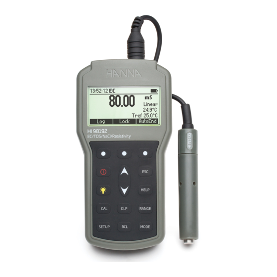
- Page 6 FRONT VIEW 1) Liquid Crystal Display (LCD). 2) F1, F2, F3 functional keys. / keys to manually increase/decrease the parameters or to scroll between the parameter list. 4) ON/OFF ( ) key, to turn the instrument ON and OFF. 5) LIGHT ( ) key to toggle display backlighting. 6) GLP key, to display Good Laboratory Practice information.
- Page 7 Range 0 to 400 mS/cm (shows values up to 1000 mS/cm) Actual conductivity 1000 mS/cm 0.001 to 9.999 µS/cm* 10.00 to 99.99 µS/cm 100.0 to 999.9 µS/cm 1.000 to 9.999 mS/cm 10.00 to 99.99 mS/cm 100.0 to 1000.0 mS/cm (autoranging) Resolution 0.001 µS/cm* / 0.01 µS/cm / 0.1 µS/cm 0.001 mS/cm / 0.01 mS/cm / 0.1 mS/cm...
- Page 8 Range % NaCl: 0.0 to 400.0 % Salinity Seawater scale: 0.00 to 80.00 (ppt) Practical salinity: 0.01 to 42.00 (PSU) Resolution 0.1 % / 0.01 ppt / 0.01 PSU Accuracy ±1% of reading Temperature Range ‑20.0 to 120.0 °C (‑4.0 to 248.0 °F) Resolution 0.1 °C (0.1 °F) Accuracy ±0.2 °C (±0.4 °F) (excluding probe error)
- Page 9 INITIAL PREPARATION The instrument is supplied complete with batteries. See Batteries Replacement for details, page 63. To prepare the instrument for field measurements close the serial communication socket with proper stopper (to ensure waterproof protection). Connect the EC probe to the DIN connector on the top of the instrument. Tighten the thread ring. Make sure the probe sleeve is properly inserted.
- Page 10 EC range The conductivity range is from 0 to 400 mS/cm. The actual conductivity range (the uncompen‑ sated conductivity) is up to 1000 mS/cm. The instrument will display conductivity readings up to 1000 mS/cm. Note: The symbol in front of the temperature reading means that the temperature can be entered by the user (Manual option selected in SETUP, or temperature out of range).
- Page 11 For practical reasons, the salinity of a solution is derived from the salinity of the seawater. Two methods of calculating the salinity from the conductivity are supported: • Natural seawater scale • Practical salinity scale Natural seawater scale (UNESCO 1966) According to the definition, salinity of a sample in ppt is calculated using the following formula: (sample) C(35;15)·r...
- Page 12 According to the definition, salinity of a sample in PSU (practical salinity units) is calculated using the following formula: ‑ coefficient; (sample) ‑ uncompensated conductivity at T °C; C(35;15)= 42.914 mS/cm ‑ the corresponding conductivity of KCl solution containing a mass of 32.4356 g KCl/1 Kg solution; ‑...
- Page 13 To reach this range press Mode while in Salinity range until the practical salinity scale [PSU] is displayed. Notes: If the meter displays the top of the range blinking, the reading is out of range. If the stability indicator “ ” blinks, the reading is unstable. Make sure the meter is calibrated before taking measurements.
- Page 14 The EC, Resistivity and TDS scales are autoranging. The meter automatically sets the scale with the highest possible resolution. By pressing Lock, the autoranging feature is disabled and the current range is frozen on the LCD. The “Range: Locked” message is displayed. To restore the autoranging option press “AutoRng” functional key again.
- Page 15 Two selectable temparature sources are available: reading directly from the sensor inside the probe or manual entry. Three options of compensating temperature are available: Linear Temperature Compensation: The conductivity of a solution with a specific electrolyte concentration changes with temperature. The relationship of the change in conductivity as a function of temperature is described by a solution’s temperature coefficient.
- Page 16 The conductivity of an aqueous solution is the measure of its ability to carry an electrical current by means of ionic motion. The conductivity invariably increases as the temperature rises. It is affected by the type and number of ions in the solution and by the viscosity of the solution itself. Both parameters are temperature dependent.
-
Page 17: Specifications
Pharmaceutical laboratories working in the US market are obliged to respect the regulations set down by the US Pharmacopoeia (USP). The 5 supplement of USP24‑NF19 lays down the rules for checking the quality of pure or fully deionized water used for the production of injection products. The conductivity of water provides information on its chemical composition. - Page 18 • Using the Stage 1 temperature and conductivity requirement table the corresponding conductivity limit at that temperature is determined. • If the measured conductivity is not greater than the table value the water meets the requirements of the test for conductivity. If the conductivity is higher than the table value, proceed with Stage 2. Stage 1 table Temperature and conductivity requirements * (for the non‑temperature compensated conductivity measurements only)
- Page 19 Stage 3 Determine the combined effect of the CO and pH. Use a Hanna Instruments pH meter. Take care that the instrument is calibrated in at least two points using pH 4.01 and pH 7.01 Hanna buffers. Perform the following test within approximately 5 minutes of the conductivity determination while maintaining the sample temperature at 25±1 °C.
- Page 20 Stage 3 pH and conductivity requirements (For atmosphere and temperature equilibrated samples only) Conductivity µS/cm...
- Page 21 Press Mode key while in EC range to enter USP mode. The instrument will display USP on the main screen. Press Stage 1 to start with first stage evaluation. Press Stage 2 to start with second stage evaluation. If Stage 1 is pressed, a tutorial screen is displayed. Use the / keys to scroll the tutorial message.
- Page 22 Press Log to store USP Stage 1 report. The report number and the amount of free log space in % is displayed for several seconds. Note: If the log space is full enter view logged data mode by pressing RCL key and free log space by deleting previously stored records.
- Page 23 Wait until the reading is stable (about 5 minutes). Note: If the input record has an instability higher than 1 mS, stability period will be reset. The completion time bar will remain empty. The “USP Met” message will be displayed if the USP Stage 2 criteria is reached. Press Report to view the USP report.
- Page 24 Press Stage 3 to enter in Stage 3 water analysis. The USP Stage 3 tutorial is displayed. Press Continue to enter USP Stage 3 analysis. The instrument will display the sample pH setting mode. Use a calibrated pH meter to read the pH value of the sample. Use / keys to set the value to that displayed on the pH meter.
- Page 25 To enter User Calibration screen press CAL key while in EC or Salinity range. From EC range Press the corresponding functional key to enter: • EC user calibration. • Probe replatinization. • Temperature user calibration. From Salinity % range Press the corresponding functional key to enter: •...
- Page 26 PROCEDURE instrument offers a choice of 7 memorized standards (0.00 µS/cm, 84.0 µS/cm, HI98192 1.413 mS/cm, 5.00 mS/cm, 12.88 mS/cm, 80.0 mS/cm and 111.8 mS/cm). For accurate EC measurements, it is recommended to perform a calibration in maximum allowed points.
- Page 27 • If necessary, press the keys / to select a different standard value. • The “ ” tag will blink on the LCD until the reading is stable. • When the reading is stable and within range of the selected buffer, CFM functional key is displayed. •...
- Page 28 • Press CFM to confirm calibration. • The calibrated value and the third expected standard value will be displayed. • After the second calibration point is confirmed, immerse the EC electrode into the third standard solution and stir gently. Tap the probe repeatedly to remove any air bubbles that may be trapped inside the sleeve.
- Page 29 • After the third calibration point is confirmed, immerse the EC electrode into the fourth standard solution and stir gently. Tap the probe repeatedly to remove any air bubbles that may be trapped inside the sleeve. • The instrument will automatically detect the standard value. •...
- Page 30 • The calibrated value and the fourth expected standard will be displayed. • After the fourth calibration point is confirmed, immerse the EC electrode into the fifth standard solution and stir gently. • If necessary, press the / keys to select a different standard value. •...
- Page 31 CLEAR CALIBRATION Press Clear functional key when displayed to clear old calibrations. All old calibrations will then be cleared and the instrument continues calibration. The points confirmed in current calibration are kept. Note: If Clear calibration is invoked during the first calibration point, the instrument returns to measurement mode.
-
Page 32: Temperature Compensation
NaCl CALIBRATION NaCl calibration is a one point procedure in 100.0% NaCl solution. Use the HI7037 calibration solution (seawater solution) as a 100% NaCl standard solution. • To enter NaCl calibration select the Salinity % range and press CAL. • The instrument enters the Salinity calibration screen. •... - Page 33 GLP is a set of functions that allows storage and retrieval of data regarding the maintenance and status of the electrode. All data regarding EC and NaCl calibration is stored for the user to review when necessary. EXPIRED CALIBRATION The instrument is provided with a real time clock (RTC), in order to monitor the time elapsed since the last EC/NaCl calibration.
-
Page 34: User Calibration
The instrument will display a lot of data including calibration standards, offset, time and date, etc. Use the / keys to select the offset or calibration standards, in order to view new information. To see more information press More. • More information regarding offset. •... - Page 35 SETUP mode allows viewing and modifying the measurement parameters. These are general SETUP parameters for all the ranges and range specific parameters. The following table lists the general SETUP parameters, their valid range and the factory default settings. Description Valid value Default Select profile Add/View or select a profile...
- Page 36 The following table lists the specific range parameters: Item Description Valid value Default Calibration Number of days after Disable, 1 to 7 days Disable Timeout calibration warning is (EC NaCl) displayed Out cal range Display warning if the Enable/Disable Disable check reading is too far from the (EC range only)
- Page 37 GENERAL PARAMETER SCREENS Select Profile Highlight Select Profile. Press Select. The list with stored profiles is displayed. Press Add to add a new profile to the list (max 10). Use the / keys to highlight the desired profile. Press Select to choose the profile and exit to SETUP. Press View to view profile information.
- Page 38 Press Delete to delete selected profile. The Delete key is displayed only if more than one profile is in the list. Press Accept to confirm the deletion or Cancel to cancel and return to the previous screen. Press ESC to return to profile list screen. Logging Interval Highlight Logging interval.
- Page 39 Contrast Highlight Contrast. Press Modify. keys to change contrast then press Accept to confirm. Press ESC to leave without changing. Auto Light Off Highlight Auto Light Off. Press 5, 10 or Disabled to change settings. Press one of the functional keys to change the option. Auto Power Off Highlight Auto Power Off.
- Page 40 Press / keys to select internal interval then press Accept. Press ESC to leave without changing. Date/Time Highlight Date/Time. Press Modify. keys to select item. Use / keys to change focused values. Press Accept to confirm new setting, or ESC to leave without changing. Time Format Highlight Time Format.
- Page 41 Language Highlight Language. Use the desired functional key to change the option. Wait until new language is loaded. If any language can be loaded, the instrument will work in safe mode. In this mode all messages are displayed in English and Help is not available. Beep On Highlight Beep On.
- Page 42 Baud Rate Highlight Baud Rate. Press Modify. / keys to select the desired communication baud. Press Accept to confirm or ESC to exit. Meter information Highlight Meter Information. Press Select. The meter information is displayed: ‑Firmware version ‑Language version ‑mV and temperature factory calibration time/date ‑Battery capacity...
-
Page 43: Ec Calibration
RANGE SPECIFIC PARAMETERS Calibration Timeout Highlight Calibration Timeout. Press Modify. keys to set desired value. Press Accept to confirm or ESC to return without saving. Note: If enabled “CAL DUE” warning will be displayed, the set number of days after calibration is over passed. - Page 44 Temperature Source Highlight Temperature Source. Press the displayed functional key in order to change the option. Select Probe in order to take the temperature automatically with the temperature sensor inside the electrode. Select Manual in order to set the temperature using the / keys. Temperature Compensation Highlight T.
- Page 45 Use the / keys to change selection. Press Accept to confirm or ESC to exit without saving. If Automatic is selected the instrument changes the range automatically according with the input. If one of the range is selected all the readings are displayed on the corresponding range. The readings will be displayed with maximum 6 digits.
- Page 46 Temperature Coefficient Highlight Temperature Coef.. Press Modify in order to set the temperature coefficient. Use the / keys to change the value. Press Accept to confirm or ESC to exit without changing. Temperature Reference Highlight Temperature Ref [°C]. Press the corresponding functional key to select the desired reference temperature. Temperature Unit Highlight Temperature Unit.
- Page 47 This feature allows the user to log up to 400 readings. All logged data can be transferred to a PC through the USB port using HI92000 application. LOGGING THE CURRENT DATA To store the current reading into memory, press LOG while in measurement mode. The instrument will display the record number and the amount of free log space for several seconds after the LOG option is selected.
- Page 48 Use / keys to highlight the desired range then press View. The list of records corresponding to the selected range is displayed. If no data were logged on the current range, the instrument will display “No Records” message. / keys to scroll between the records from the list. Press Delete All to enter Delete All screen.
- Page 49 / keys to select the desired record. Press Delete to enter delete one record mode. Press Delete All to enter delete all mode. Press More to view the complete record information. Press Pg Down or Pg Up to scroll the record screens.
-
Page 50: Setup
This feature allows the user to log up to 1000 readings. All logged data can be transferred to PC through USB port. The memory space is organized in lots of records. A lot can contain from 1 to 1000 records. The maximum available lots number is 100. -
Page 51: Autolog
Press AutoLog to enter the automatic log range selection. / keys to highlight the desired range, then press View. The list of lots corresponding to the selected range is displayed. If no data were logged on the current range, the instruments will display “No Records!”. Use / keys to scroll the lot list. -
Page 52: Autoend
To freeze the first stable reading on the LCD press AutoEnd while the instrument is in measurement mode. The ”Wait” symbol will blink until the reading is stable. When the reading is stable, “Hold” icon will be displayed. Press Continue in order to enter continuous reading mode. - Page 53 All the instruments are factory calibrated for temperature. Hanna’s temperature probes are interchangeable and no temperature calibration is needed when they are replaced. If the temperature measurements are inaccurate, temperature recalibration should be performed. For an accurate recalibration, contact your dealer or the nearest Hanna Customer Service Center, or follow the instructions below.
- Page 54 • Press CFM to confirm. • The second expected calibrated point is displayed. • Immerse the probe into the second vessel as close as possible to the reference thermometer. Allow a few seconds for the probe to stabilize. • Use the / keys to set the calibration point value to that measured by the reference thermometer.
- Page 55 Note: If the reading is not within range of the selected calibration point or the difference between first selected point and second selected point is less than 25 °C, “Wrong” message will blink. If the Wrong source is the difference between calibration points increase the temperature of the vessel with hot water.
- Page 56 USB socket and the other to the serial or USB port of your PC. Note: If you are not using Hanna Instruments HI92000 software, please see the following instructions. SENDING COMMANDS FROM PC It is also possible to remotely control the instrument with any terminal program.
- Page 57 CHR xx Change the instrument range according with the parameter value (xx): • xx=10 EC range • xx=11 Resistivity range • xx=12 TDS range • xx=13 USP range • xx=14 NaCl % range • xx=15 Salinity, Seawater range • xx=16 Salinity, PSU range The instrument will answer for these commands with: <STX>...
- Page 58 • xx=15 Salinity, Seawater range • xx=16 Salinity, PSU range • Meter status (2 chars of status byte): represents a 8 bit hexadecimal encoding. • 0x10 ‑ temperature probe is connected • 0x20 ‑ autolog in progress • 0x01 ‑ new GLP data available •...
- Page 59 PRFxx Request profile “xx” information The answer string contains: 10 ‑ EC range 11 ‑ Resistivity range 12 ‑ TDS range 13 ‑ USP range 14 ‑ NaCl % range 15 ‑ Salinity, Seawater range 16 ‑ Salinity, Seawater PSU range •...
- Page 60 Requests the setup parameters setting. The answer string contains: • Number of profiles (2 chars) • Current profile ID (2 chars) • Number of languages (2 chars) NSLx Requests the number of logged samples. The command parameter (1 char): • E ‑ the request is for EC range •...
- Page 61 • Temperature coefficient (6 chars) • Offset factor (6 chars) • TDS factor (6 chars) (only for TDS lots) • Salinity coefficient (7 chars) (only for salinity lots) • Profile ID (4 chars) • Profile creation time (12 chars) • Lot start time (12 chars) Lot record data: •...
- Page 62 • The calibration standard unit (1 char) • Offset factor (6 chars) • Temperature reading (8 chars) • Resistivity or TDS or salinity reading (8 chars) • Unit (1 char) • TDS factor (6 chars) or salinity coefficient (7 chars) •...
- Page 63 To replace the batteries, follow the next steps: • Turn OFF the instrument. • Open the battery compartment by removing the four screws from the back of the instrument. • Remove the old batteries. • Insert four new 1.5V AA batteries in the battery compartment while paying attention to the correct polarity.
- Page 64 Replace the probe. gives faulty readings. At startup the meter displays One of the keys is blocked. Contact your dealer at any Hanna Logo tags Hanna Instruments Service permanently. Center. Meter shuts off. Dead accumulators, Auto Recharge accumulators or Power Off feature is enabled: replace accumulator.
- Page 65 Rinse the probe with clean water after measurements. If more cleaning is required, remove the probe sleeve and clean the probe with a cloth or a nonabrasive detergent. Make sure to reinsert the sleeve onto the probe properly and in the right direction. After cleaning the probe, recalibrate the instrument. The platinum rings are sustained with glass.
- Page 66 The replatinization process takes about 5 minutes. Remove the probe from the replatinization solution and rinse it with deionized water. Code Description HI70031C 1413 µS/cm, 20 ml sachet, 25 pcs. HI70039C 5000 µS/cm, 20 ml sachet, 25 pcs. HI70030C 12880 µS/cm, 20 ml sachet, 25 pcs. HI6033 84 µS/cm, 500 ml bottle HI6031...
- Page 67 Technical Service department and then send it with shipping costs prepaid. When shipping any instrument, make sure it is properly packed for complete protection. Hanna Instruments reserves the right to modify the design, construction or appearance of its products without advance notice.
- Page 68 World Headquarters Hanna Instruments Inc. Highland Industrial Park 584 Park East Drive Woonsocket, RI 02895 USA www.hannainst.com Local Office Hanna Instruments USA 270 George Washington Highway Smithfield, RI 02917 Phone: 800.426.6287 Fax: 401.765.7575 e‑mail: tech@hannainst.com MAN98192 03/16 Printed in ROMANIA...
Need help?
Do you have a question about the HI98192 and is the answer not in the manual?
Questions and answers