
Related Manuals for Hanna Instruments HI981954


Summary of Contents for Hanna Instruments HI981954
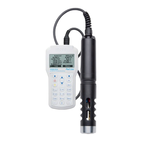
- Page 1 HI981954 Multiparameter Portable Meter pH/mV, ORP, EC, TDS, Resistivity, Salinity, Seawater σ, Atmospheric Pressure & Temperature...
- Page 2 If you need additional technical information, do not hesitate to e‑mail us at tech@hannainst.com or view our worldwide contact list at www.hannainst.com. All rights are reserved. Reproduction in whole or in part is prohibited without the written consent of the copyright owner, Hanna Instruments Inc., Woonsocket, Rhode Island, 02895, USA.
-
Page 3: Table Of Contents
TABLE OF CONTENTS 1. PRELIMINARY EXAMINATION ....................5 2. GENERAL DESCRIPTION ....................... 6 3. SPECIFICATIONS ......................... 7 3.1. METER SPECIFICATIONS .................... 7 3.2. PROBE SPECIFICATIONS .................... 9 3.3. SENSOR SPECIFICATIONS ..................9 4. DISPLAY & KEYBOARD DESCRIPTION .................. 11 5. SENSOR PREPARATION & INSTALLATION ................13 5.1. - Page 4 9. SYSTEM SETUP ......................... 37 9.1. METER SETUP ......................37 9.2. PROBE SETUP ......................40 10. STATUS ......................... 41 10.1. METER STATUS ..................... 41 10.2. PROBE STATUS ..................... 41 10.3. GLP ........................42 11. MEASUREMENT ......................44 12. LOGGING ........................45 12.1.
-
Page 5: Preliminary Examination
1. PRELIMINARY EXAMINATION Remove the instrument and accessories from the packaging and examine them carefully. For further assistance, please contact your local Hanna Instruments Office or email us at tech@hannainst.com. HI981954 is delivered in a rugged carrying case and is supplied with: •... -
Page 6: General Description
2. GENERAL DESCRIPTION Part of Hanna Instruments pool-line family, HI981954 is a waterproof portable logging multiparameter system (meter and probe), that monitors up to 11 different water quality parameters (5 measured, 6 calculated) such as pH, ORP, conductivity, and temperature. -
Page 7: Specifications
3. SPECIFICATIONS 3.1. METER SPECIFICATIONS Range 0.00 to 14.00 pH; ± 600.0 mV Resolution 0.01 pH; 0.1 mV pH / mV Accuracy ± 0.02 pH; ± 0.5 mV Automatic at 1, 2 or 3 points with automatic recognition of 5 standard Calibration buffers (pH 4.01, 6.86, 7.01, 9.18, 10.01) and 1 custom buffer Range... - Page 8 Range 0 to 999999 Ω·cm; 0 to 1000.0 kΩ·cm; 0 to 1.0000 MΩ·cm Resistivity Resolution Depending on resistivity reading Calibration Based on conductivity calibration Range 0.00 to 70.00 PSU Resolution 0.01 PSU Salinity Accuracy ±2% of reading or ±0.01 PSU whichever is greater Calibration Based on conductivity calibration Range 0.0 to 50.0 σ...
-
Page 9: Probe Specifications
3.2. PROBE SPECIFICATIONS Sensor Inputs Two (pH or pH/ORP, EC) Sample Environment Fresh, brackish, seawater IP68 (waterproof) Protection Rating Operating Temperature -5 to 55 °C (23 to 131 °F) Storage Temperature -20 to 70 °C (-4 to 158 °F) Maximum Depth 20 m (66’) Dimensions 342 mm (13.5”), Ø... - Page 10 Description pH/ORP sensor Measurement Type pH, mV (pH/ORP) Measurement Range 0.00 to 13.00 pH; ±600.0 mV; ±2000.0 mV Temperature Range -5.0 to 55.0 °C (23.0 to 131.0 °F) Color Code Glass (pH); Pt (ORP) Glass Type LT (low temperature) HI7698194-1 Junction Ceramic Materials...
-
Page 11: Display & Keyboard Description
4. DISPLAY & KEYBOARD DESCRIPTION Front View 1. Liquid Crystal Display (LCD) 2. Battery level indicator 3. Functional keys (soft keys), press to perform the function displayed above them on the screen 4. Power (On / Off) key, press to turn the meter on and off 5. - Page 12 Top View 11. DIN connector for probe connection 12. Micro USB connector with protective cap HI7698195 Multisensor Probe 1. Strain relief 2. Probe body 3. Protective shield...
-
Page 13: Sensor Preparation & Installation
5. SENSOR PREPARATION & INSTALLATION 5.1. SENSOR TYPES & DESCRIPTIONS HI7698194-0 Combination pH sensor features a glass pH sensitive bulb and a silver/silver chloride double junction reference with gelled electrolyte. HI7698194-1 Combination pH/ORP sensor features a glass sensitive bulb for pH readings, a platinum sensor for redox measurements and a silver/silver chloride double junction reference with gelled electrolyte. -
Page 14: Sensor Installation
For reducing pretreatment: immerse the electrode for at least five minutes in HI7091. For oxidizing pretreatment: immerse the electrode for at least five minutes in HI7092. 5.3. SENSOR INSTALLATION HI7698195 probe sensor connector sockets are identified with color-coded triangles: • CONN1 - red connector (one triangle): pH or pH/ORP sensor •... -
Page 15: Sensor Maintenance
4. Continue to tighten the locking threads with the small hex key supplied in the maintenance kit until the sensor is secured tightly against the probe body. 5. The sensors have to be conditioned and calibrated before use. 6. Screw the protective shield onto the probe body, to protect the sensors. Note: To maintain a waterproof probe, if a sensor is not installed a plug must be inserted. - Page 16 • Rinse the sensor in flowing water then clean the sensor by soaking it for 1 minute in HI70670 Cleaning solution for mineral deposits or HI70671 Cleaning & disinfection solution for algae, fungi and bacteria. After cleaning soak the sensor in HI703004 Storage solution for 30 minutes before taking measurements.
-
Page 17: General Operations
6. GENERAL OPERATIONS 6.1. BATTERY CAPACITY & REPLACEMENT HI981954 is supplied with 4 Alkaline, 1.5 V AA batteries. The battery level indicator on the LCD indicates the remaining battery life. If the battery capacity is less than 10%, the indicator is displayed blinking and the batteries should be replaced with new ones. -
Page 18: Connecting The Probe
6.3. TURNING THE METER ON After connecting the sensors to the probe and connecting the probe to the meter, turn the meter on by pressing the On/Off key. At start-up the display will show the Hanna Instruments logo, meter name and firmware version. -
Page 19: Basic Operations
After the initialization has been completed if the probe is connected, the meter displays the Probe Status screen. The probe status screen identifies the probe and attached sensors. Press Measure to view the measurement screen. Log and Menu functional keys are displayed. Press Param. -
Page 20: Functional Diagram Of The Instrument
6.5. FUNCTIONAL DIAGRAM OF THE INSTRUMENT Menu and Log functional keys help user navigate through all measurement operations. The following diagrams present an overview of possible functions. Menu Select Parameters Parameter Units One sample on meter Parameter Coefficients Start Meter Log Parameter Setup Averaging Log Recall... -
Page 21: Parameter Setup
7. PARAMETER SETUP From the measurement screen press Menu. Use the arrow keys to highlight “Parameter Setup” and press Select. Use the arrow keys to highlight the desired option and press Select. Warning: Logged data saved on the meter will be changed to selected parameter units or coefficients. - Page 22 Pressure Unit Option: psi, mmHg, inHg, mbar, atm, kPa Press Modify and use the arrow keys to select the desired pressure unit. Press Select to confirm or the ESC key to return to the previous screen. Resistivity Unit Option: Ω·cm, kΩ·cm, MΩ·cm Resistivity is calculated from the conductivity measurement.
- Page 23 EC Resolution Option: Auto, Auto mS/cm, 1 μS/cm, 0.001 mS/cm, 0.01 mS/cm, 0.1 mS/cm, 1 mS/cm Press Modify and use the arrow keys to select the desired EC resolution. Press Select to confirm or the ESC key to return to the previous screen. Auto: The meter automatically chooses the range (µS/cm or mS/cm) to optimize the measurement.
-
Page 24: Parameter Coefficients
TDS Resolution Option: Auto, Auto ppt, 1 ppm, 0.001 ppt, 0.01 ppt, 0.1 ppt, 1 ppt Press Modify and use the arrow keys to select the desired TDS resolution. Press Select to confirm or the ESC key to return to the previous screen. Auto: The meter automatically chooses the range (ppm or ppt) to optimize the measurement. -
Page 25: Averaging
Press Accept to confirm the value or the ESC key to return to the previous screen. TDS Factor Option: 0.00 to 1.00 TDS is a calculated value based on the conductivity of the solution (TDS = factor x EC ). A typical TDS factor for strong ionic solutions is 0.50, while for weak ionic solutions is 0.70 (e.g fertilizers). -
Page 26: Calibration
8. CALIBRATION In the measurement screen press Menu. Use the arrow keys to highlight “Calibration” and press Select. Use the arrow keys to highlight the desired option and press Select. All calibration data is stored in the non volatile probe memory, allowing probes to be connected to different meters without recalibration. -
Page 27: Quick Calibration
8.1. QUICK CALIBRATION The quick calibration provides a single point calibration for pH and conductivity sensors. The user can select to calibrate one or both sensors. HI9828-0 calibration solution is used for both pH and conductivity. If a sensor is already calibrated or to skip a calibration, press Skip. 1. -
Page 28: Ph Calibration
8.2. pH CALIBRATION To optimize the pH measurement follow the general guidelines mentioned in the introduction of the CALIBRATION section. From the “Calibration” menu select “Single param. calibration” and then “pH”. Options: • Calibrate pH: Perform a new calibration using up to 3 buffers (pH 4.01, 6.86, 7.01, 9.18, 10.01 or one custom buffer). - Page 29 Press OK to return to the calibration menu or Measure to return to the measurement screen. pH Calibration Error Messages HI981954 displays a series of messages if an error has occurred during calibration. • “Input out of scale”: the pH value is out of range. The pH sensor may require replacement.
- Page 30 • “Wrong buffer” / “Contaminated buffer” / “Check electrode”: the buffer is contaminated or the sensor is broken or very dirty. • “Wrong” / “Clear old calibration”: erroneous slope condition. These messages appear if the slope difference between the current and previous calibration exceeds the slope window (80% to 110%). Press Clear to cancel the old data and continue the calibration procedure, or press ESC to quit the pH calibration mode.
-
Page 31: Orp Calibration
8.3. ORP CALIBRATION The Oxidation-Reduction Potential (ORP), displayed in mV, is the voltage that results from the difference in potential between the platinum ORP sensor and the Ag/AgCl reference electrode. ORP values are not temperature compensated, although ORP values can change with temperature (e.g. reference electrode potential changes, sample equilibrium changes). -
Page 32: Conductivity Calibration
6. Wait a few minutes for the measurement to stabilize. Use the arrow keys to select “Custom ORP” and press Select to start the calibration. A text box window will appear. Use the keypad to enter the value of the solution at the current temperature. Press Accept to confirm calibration point. 7. - Page 33 5. Slowly place the sensors in the solution. Dislodge bubbles that may adhere to the sensors. 6. Use the arrow keys to select “Conductivity” and press Select to start the calibration. 7. If necessary, press Cal. point to select the correct standard. To use a custom standard, press Custom.
- Page 34 Salinity Calibration Procedure The measurement of salinity is based on the Practical Salinity Scale which uses the EC measurement. If the user has a standard with known PSU value it may be used to calibrate the conductivity sensor. 1. Remove the shield from the probe. Rinse the probe with purified water. 2.
-
Page 35: Temperature Calibration
8.5. TEMPERATURE CALIBRATION From the “Calibration” menu select “Single param. calibration” and then “Temperature”. Options: • Calibrate temperature: The user can perform a one-point calibration. • Restore factory calib.: Clears previous user calibration. Procedure 1. Remove the shield from the probe. Rinse the probe with purified water. 2. - Page 36 Atmospheric Pressure Calibration Procedure 1. Use a reference barometer to obtain the true local barometric pressure reading. 2. Use the arrow keys to select “Custom Pressure” and press Select to start the calibration. 3. A text box window will appear. Use the keypad to enter the calibration pressure (600.0 to 1133.2 mbar).
-
Page 37: System Setup
9. SYSTEM SETUP From the main menu, select “System setup” and then “Meter setup” or “Probe setup”. Note: When the password protection is enabled, authentication will be required before any modification. 9.1. METER SETUP There are 12 items in the Meter Setup menu. Pressing the corresponding numerical value will bring the user directly to that position in the list. - Page 38 Auto Poweroff Option: not used, 5, 10, 15, 20, 30, 60 minutes The function is used to save battery life. After the set time is elapsed, the meter will: 1. Automatically switch off, if no key is pressed in normal measurement mode. Press On/Off key to switch on again.
- Page 39 LCD Contrast Option: 0 to 15 Press Modify and use the arrow keys to increase or decrease the display contrast. Press Accept to save or press ESC key to return to the menu. LCD Backlight Option: 0 to 10 Press Modify and use the arrow keys to change LCD backlight intensity. Press Accept to save or press ESC key return to the menu.
-
Page 40: Probe Setup
Meter ID Option: Up to 14 characters Press Modify to enter meter’s ID setup screen. Use the keypad to set or change the meter’s ID. Press Accept to save or ESC to return to the menu. Language Option: Español, English, Deutsch, Italiano, Portugues Press Modify and use the arrow keys to change the language. -
Page 41: Status
10. STATUS In the measurement screen press Menu. Use the arrow keys to highlight “Status” and press Select. Use the arrow keys to highlight the desired option and press Select. 10.1. METER STATUS Meter Status displays information related to the batteries, charging status, logging, internal temperature, password, Meter ID, serial number and firmware version. -
Page 42: Glp
GLP screen displays: offset, acidic slope, basic slope, buffers used, time and date of the calibration. Notes: A “C” label near the buffer value indicates a custom point, while an “H” indicates a Hanna Instruments standard buffer value. If a quick calibration was performed, buffer values are replaced with “Quick calibration” indication. - Page 43 Temperature Temperature GLP screen displays: calibrated point, time and date. Atmospheric Pressure Atmospheric pressure GLP screen displays: custom calibration point, time and date.
-
Page 44: Measurement
11. MEASUREMENT During measurement mode HI981954 will simultaneously measure data for all enabled parameters. Use the numbers 1 through 7 on the keypad to select the number of parameters that are shown on the screen at one time. The display will automatically resize the digits to fit the screen. -
Page 45: Logging
12. LOGGING HI981954 and the HI7698195 multi-sensor probe offer two types of logging: meter only parameters, and meter and probe parameters. From measurement mode, press Log to access Log menu. The data logged on the meter are organized by lots. Up to 45,000 complete records can be stored in up to 100 lots. -
Page 46: Start Meter Log
12.2. START METER LOG 1. Select “Start meter log” to log the currently enabled parameters at the set logging interval on the meter. 2. To set the logging interval, press Options. The log interval time can set from 1 second to 3 hours. - Page 47 4. Press Data to return to the previous screen or Jump to select a different sample in the same lot. When Jump is pressed, a text box appears to insert the desired sample number. 5. Press ESC to return to the menu. 6.
-
Page 48: Log Notes
12.4. LOG NOTES Remarks The meter can store up to 20 remarks. A remark can be associated with each sample. To add a new remark: 1. Select “Log notes” from Log menu, then “Remarks”. Display shows a list of stored remarks. 2. -
Page 49: Pc Connection
13. PC CONNECTION The logged data from a probe or meter can be transferred to a PC using the HI9298194 application. ® The software is compatible with Windows 10 & below. HI9298194 software offers a variety of features (meter info, parameters, view & plot, export or delete log data and on-line help). - Page 50 Meter to PC data a. Select parameter units b. Select Meter from toolbar c. Select Lot...
-
Page 51: Probe Deployment
14. PROBE DEPLOYMENT The Hanna Instruments HI7698195 have been designed for a variety of water quality measurements both in situ or in active deployments in urban or natural waters. HI981954 system may be used for discrete spot sampling with log on demand function or, continuous monitoring and logging. - Page 52 Measurements in a flow cell The probe is suitable for measurements in a flow cell. Pumping water to a flow-through monitoring station has obvious pros and cons. • Typically a shelter is required to secure a pump, and flow chamber. •...
-
Page 53: Troubleshooting / Error Messages
‘’Warning x’’: Any other warning that appears at power-on is identified using a numeric code. Restart the meter. If the problem persists, contact your local Hanna Instruments Office. Some meter/probe features can be accessed but with no guarantee. ‘’Errors x’’: Any critical errors that appear are identified using a numeric code, and the meter is automatically switched off. -
Page 54: Accessories
16. ACCESSORIES Probes Packed in Carton Box, without Sensors or Protective Shield Code Description HI7698195/4 HI7698195 probe with 4 m (13.1’) cable HI7698195/10 HI7698195 probe with 10 m (33.0’) cable HI7698195/20 HI7698195 probe with 20 m (65.6’) cable HI7698195/40 HI7698195 probe with 40 m (131.2’) cable Note: Probes with different cable length are available upon request. - Page 55 pH Buffers Code Description HI5004 pH 4.01 buffer solution, 500 mL HI5005 pH 5.00 buffer solution, 500 mL HI5006 pH 6.00 buffer solution, 500 mL HI5068 pH 6.86 buffer solution, 500 mL HI5007 pH 7.01 buffer solution, 500 mL HI5074 pH 7.41 buffer solution, 500 mL HI5008 pH 8.00 buffer solution, 500 mL...
- Page 56 Conductivity Standard Solutions Code Description HI7030L 12880 µS/cm calibration solution, 500 mL HI7031L 1413 µS/cm calibration solution, 500 mL HI7033L 84 µS/cm calibration solution, 500 mL HI7034L 80000 µS/cm calibration solution, 500 mL HI7035L 111800 µS/cm calibration solution, 500 mL HI7039L 5000 µS/cm calibration solution, 500 mL HI700304P...
-
Page 57: Certification
CERTIFICATION All Hanna Instruments conform to the CE European Directives. RoHS compliant Disposal of Electrical & Electronic Equipment. The product should not be treated as household waste. Instead hand it over to the appropriate collection point for the recycling of electrical and electronic equipment which will conserve natural resources. -
Page 58: Warranty
If service is required, contact your local Hanna Instruments Office. If under warranty, report the model number, date of purchase, serial number (see engraved on the back of the instrument) and the nature of the problem. - Page 59 Hanna Instruments reserves the right to modify the design, construction or appearance of its products without advance notice.
- Page 60 World Headquarters Hanna Instruments Inc. Highland Industrial Park 584 Park East Drive Woonsocket, RI 02895 USA www.hannainst.com MAN981954 Printed in ROMANIA...
Need help?
Do you have a question about the HI981954 and is the answer not in the manual?
Questions and answers