Table of Contents
Advertisement
Quick Links
OPERATION AND PARTS MANUAL
®
WHISPERWATT™ SERIES
MODEL DCA150USJ3CAN
60HZ GENERATOR
(JOHN DEERE 6068HF285 DIESEL ENGINE)
PARTS LIST NO. M3874400114
Revision #1 (05/19/15)
To find the latest revision of this
publication, visit our website at:
www.multiquip.com
THIS MANUAL MUST ACCOMPANY THE EQUIPMENT AT ALL TIMES.
Advertisement
Table of Contents
Troubleshooting

Related Manuals for MULTIQUIP WHISPERWATT DCA150USJ3CAN


Summary of Contents for MULTIQUIP WHISPERWATT DCA150USJ3CAN
- Page 1 WHISPERWATT™ SERIES MODEL DCA150USJ3CAN 60HZ GENERATOR (JOHN DEERE 6068HF285 DIESEL ENGINE) PARTS LIST NO. M3874400114 Revision #1 (05/19/15) To find the latest revision of this publication, visit our website at: www.multiquip.com THIS MANUAL MUST ACCOMPANY THE EQUIPMENT AT ALL TIMES.
-
Page 2: Fuel And Chemical Exposure Warnings
FUEL AND CHEMICAL EXPOSURE WARNINGS Diesel engine exhaust and some of its constituents are know to cause cancer, birth defects and other reproductive harm. PAGE 2 — DCA150USJ3CAN 60 HZ GENERATOR • OPERATION AND PARTS MANUAL — REV. #1 (05/19/15) -
Page 3: Reporting Safety Defects
If you believe that your vehicle has a defect that could cause a crash or could cause injury or death, you should immediately inform the National Highway Traffi c Safety Administration (NHTSA) in addition to notifying Multiquip Inc. at 1-800-421-1244. -
Page 4: Table Of Contents
TABLE OF CONTENTS DCA150USJ3CAN 60 Hz- Component Drawings Generator Generator Assembly ......... 74-75 Control Box Assembly ........76-79 Fuel And Chemical Exposure Warnings ....2 Engine And Radiator Assembly ......80-83 Reporting Safety Defects ......... 3 Output Terminal Assembly ........ 84-87 Table Of Contents ............ -
Page 5: Parts Ordering Procedures
, 2006 Order via Internet (Dealers Only) Best Deal! If you have an MQ Account, to obtain a Username Order parts on-line using Multiquip’s SmartEquip website! and Password, E-mail us at: parts@multiquip. com. ■ View Parts Diagrams ■ Order Parts To obtain an MQ Account, contact your District Sales Manager for more information. -
Page 6: Safety Information
SAFETY INFORMATION Do not operate or service the equipment before reading the Potential hazards associated with the operation of this entire manual. Safety precautions should be followed at all equipment will be referenced with hazard symbols which times when operating this equipment. Failure to read and may appear throughout this manual in conjunction with understand the safety messages and operating instructions safety messages. - Page 7 SAFETY INFORMATION GENERAL SAFETY „ NEVER use accessories or attachments that are not recommended by MQ Power for this equipment. Damage CAUTION to the equipment and/or injury to user may result. „ NEVER operate this equipment without proper protective „ ALWAYS know the location of the nearest clothing, shatterproof glasses, respiratory protection, fi re extinguisher.
- Page 8 SAFETY INFORMATION ENGINE SAFETY NOTICE DANGER „ NEVER run engine without an air fi lter or with a dirty air fi lter. Severe engine damage may occur. Service air fi lter „ The engine fuel exhaust gases contain poisonous carbon frequently to prevent engine malfunction.
- Page 9 SAFETY INFORMATION FUEL SAFETY „ Make sure the hitch and coupling of the towing vehicle are rated equal to, or greater than the trailer “gross DANGER vehicle weight rating.” „ DO NOT start the engine near spilled fuel or combustible „...
- Page 10 SAFETY INFORMATION ELECTRICAL SAFETY „ Make sure power cables are securely connected to the generator’s output receptacles. Incorrect connections DANGER may cause electrical shock and damage to the generator. „ DO NOT touch output terminals during operation. Contact with output terminals NOTICE during operation can cause electrocution, „...
-
Page 11: Safety Information
SAFETY INFORMATION EMISSIONS INFORMATION „ If the battery liquid (dilute sulfuric acid) comes into contact with clothing or skin, rinse skin or clothing NOTICE immediately with plenty of water. The diesel engine used in this equipment has been „ If the battery liquid (dilute sulfuric acid) comes into designed to reduce harmful levels of carbon monoxide contact with eyes, rinse eyes immediately with plenty (CO), hydrocarbons (HC) and nitrogen oxides (NOx) -
Page 12: Specifications
SPECIFICATIONS Table 1. Generator Specifications Model DCA150USJ3CAN Revolving field, self ventilated, Type open protected type synchronous generator Armature Connection Star with Neutral Zigzag Phase Single Standby Output 132 KW (165 kVA) 95.7 KW Prime Output 120 KW (150 kVA) 87 KW 3Ø/1Ø... -
Page 13: Dimensions
DIMENSIONS Figure 1. Dimensions Table 3. Dimensions Reference Dimension in. (mm) Reference Letter Dimension in. (mm) Letter 42.50 in. (1080 mm.) 128.00 in. (3,250 mm.) 40.20 in. (1020 mm.) 75.00 in. (1,905 mm.) 40.90 in. (1040 mm.) 48.80 in. (1240 mm.) 40.20 in. -
Page 14: Installation
INSTALLATION GENERATOR GROUND LUG GROUND ROD FOR EARTH GROUND. GROUND CABLE CONNECT TO BUILDING GROUND IF APPLICABLE I N I T . / 2 REFERENCE NEC 250-83 (C) Figure 2. Typical Generator Grounding Application PAGE 14 — DCA150USJ3CAN 60 HZ GENERATOR • OPERATION AND PARTS MANUAL — REV. #1 (05/19/15) - Page 15 INSTALLATION OUTDOOR INSTALLATION GENERATOR GROUNDING Install the generator in a area that is free of debris, To guard against electrical shock and possible damage to bystanders, and overhead obstructions. Make sure the the equipment, it is important to provide a good EARTH generator is on secure level ground so that it cannot slide ground.
-
Page 16: General Information
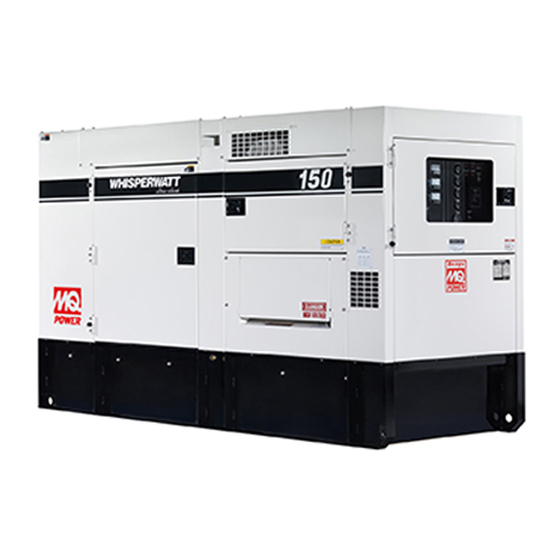
GENERAL INFORMATION GENERATOR OPEN DELTA EXCITATION SYSTEM This generator is equipped with the state of the art “Open- This MQ Power generator (Figure 3) is a high quality Delta” excitation system. The open delta system consist portable (requires a trailer for transport) power source for telecom sites, lighting facilities, power tools, submersible of an electrically independent winding wound among pumps and other industrial and construction machinery. -
Page 17: Major Components
MAJOR COMPONENTS Table 4. Generator Major Components ITEM NO. DESCRIPTION Muffler Assembly Engine Assembly Air Filter Assembly Generator Assembly Battery Assembly Output Terminal Assembly Fuel Tank Assembly Generator Control Panel Assembly Engine Operating Panel Assembly Figure 3. Major Components DCA150USJ3CAN 60 HZ GENERATOR • OPERATION AND PARTS MANUAL — REV. #1 (05/19/15) — PAGE 17... -
Page 18: Diagnostic Display
DIAGNOSTIC DISPLAY 2. Left Arrow Button – Press this button to scroll through the screen either moving the parameter selection toward the left or upward. 3. Right Arrow Button – Press this button to scroll through the screen either moving the parameter selection toward the right or downward. - Page 19 DIAGNOSTIC DISPLAY First Time Start Up 2. The first seven items of the “Main Menu” will be displayed. Touching the “Arrow Buttons” will scroll 1. When power is first applied to the diagnostic display, through the menu selection. the “Logo” is displayed. GO TO 1-UP DISPLAY LANGUAGES STORED CODES...
- Page 20 DIAGNOSTIC DISPLAY 4. If the word “MORE” appears above the “Arrow Buttons” 2. The language choices will be displayed. Use the there are more stored fault codes that may be viewed. “Arrow” buttons to scroll through the selections and Use the “Arrow Buttons” to scroll to the next Stored touch “Enter”...
- Page 21 DIAGNOSTIC DISPLAY First Time Start-Up 2. The The first seven items of the “Main Menu” will be displayed. Touching the “Arrow Buttons” will scroll 1. When power is first applied to the diagnostic display, through thr menu selection. the “Logo” is displayed. GO TO 1-UP DISPLAY LANGUAGES STORED CODES...
- Page 22 DIAGNOSTIC DISPLAY 2. The language choices will be displayed. Use the 4. f the word “MORE” appears above the “Arrow Buttons” “Arrow” buttons to scroll through the selections and there are more stored fault codes that may be viewed. touch “Enter” to make a selection. Use the “Arrow Buttons”...
- Page 23 DIAGNOSTIC DISPLAY FAULTS AND WARNING 2. The main menu will pop up on the display. Use the “Arrow Buttons” to scroll through the menu until the Auxiliary Gage Fault “Engine Configuration” menu item has been highlighted 1. During normal operation the single or four parameter screen will be displayed.
- Page 24 DIAGNOSTIC DISPLAY 4. To acknowledge and “Hide” the fault and return to the Indicates Auxiliary Gage Fault single or four parameter display touch the “Enter Indicates Fault Warning Indicates Derate or Shutdown Condition Fault Button”. 5. Touching the “Enter Button” will redisplay the hidden fault.
- Page 25 DIAGNOSTIC DISPLAY Shutdown Codes 5. Touching the “Enter Button” once again will hide the fault and return the screen to the single or four 1. During normal operation the single or four parameter parameter display. screen will be displayed SHUTDOWN 1 of x SPN110 FMI10 1000 RPM...
- Page 26 DIAGNOSTIC DISPLAY CONTRAST ADJUSTMENT 3. Once the “Adjust Backlight” menu item has been highlighted touch the “Enter Button” to activate the 1. Starting at the single or four engine parameter display, “Adjust Backlight” function touch the “Menu Button”. GO TO 1-UP DISPLAY 1000 RPM STORED CODES ENG RPM...
- Page 27 DIAGNOSTIC DISPLAY Select Units 5. Touch the “Enter Button” to select the highlighted units. 1. Starting at the single or four engine parameter display touch the “Menu Button”. ENGLISH METRIC KPA METRIC BAR 1000 RPM ENG RPM LOAD RPM 1500 3000 1800 RPM 14.2...
- Page 28 DIAGNOSTIC DISPLAY 3. Once the “Setup 1-up Display” menu icon has been 7. A message indicating the “Single Engine” parameter highlighted touch the “Enter Button” to access the display parameters are reset to the factory defaults will “Setup 1-up display” function. be displayed, then the display will return to the “Custom Setup”...
- Page 29 DIAGNOSTIC DISPLAY 11. Touch the “Enter Button” to deselect the selected 16. Touching the “Enter Button” toggles the “Automatic parameter removing it from the list of parameters being Scan” function on. displayed on the 1-up display. USE DEFAULTS CUSTOM SETUP AUTOMATIC SCAN ON ENGINE SPEED PERCENT LOAD AT CURRENT RPM...
- Page 30 DIAGNOSTIC DISPLAY Setup 4-Up Display 5. The “Use Defaults” screen will be displayed during the resetting period then will automatically return to the 1. From the single or four engine parameter display touch “Setup 4- Up Display” menu. the “Menu Button 1000 RPM RESTORED TO ENG RPM...
- Page 31 DIAGNOSTIC DISPLAY 9. The parameter that is highlighted is the selected 14. Touch the “Menu Button” to return to the main menu. parameter for the screen. Use the “Arrow Buttons” to highlight the new parameter to be placed in the quadrant selected in the previous screen.
- Page 32 DIAGNOSTIC DISPLAY 8. When the gage data has cleared, the display 4. Touch “Select” to enter the “Gage Data” display. When automatically returns to the “Utilities” menu. Scroll to “Gage Data” is selected the PowerView will communicate “Software Version”. Touch “Select” to view the software with the analog gages at a fixed rate of 38.4k Band, 8 version currently in the diagnostic display.
- Page 33 DIAGNOSTIC DISPLAY 11. Touch the “Menu” button to return to “Utilities” menu. 4. Use the “Arrows” to scroll down to and highlight either Touch the “Menu button again to return to the “Main” the “Slave Active or Master Active” modes. Touch the menu.
-
Page 34: Diagnostic Display
DIAGNOSTIC DISPLAY GLOSSARY (Troubleshooting Information) CANBUS FAILURE Diagnostic Display has not received any CAN messages for at least 30 seconds. NO DATA Diagnostic Display has not received the particular message being displayed for at least 5 seconds. NOT SUPPORTED Diagnostic Display has received a message from the ECU stating the displayed message is not supported DATA ERROR Diagnostic Display has received an error message from the ECU for the displayed message. -
Page 35: Generator Control Panel
GENERATOR CONTROL PANEL INCREASE DECREASE AUTO MANUAL OFF/RESET LOW OIL PRESSURE HIGH COOLANT TEMPERATURE OVERCRANK OVERSPEED ENGINE RUNNING MOOOOO-20001Q Figure 5. Generator Control Panel The definitions below describe the controls and functions Located behind the generator control panel is the Generator of the Generator Control Panel (Figure 5). -
Page 36: Engine Operating Panel
ENGINE OPERATING PANEL INCREASE DECREASE AUTO MANUAL OFF/RESET LOW OIL PRESSURE HIGH COOLANT TEMPERATURE OVERCRANK OVERSPEED ENGINE RUNNING MOOOOO-20001Q Figure 6. Engine Operating Panel The definitions below describe the controls and functions 6. Fuel Leak Detected Alarm Lamp – This lamp will of the Engine Operating Panel (Figure 6). - Page 37 ENGINE OPERATING PANEL 11. Tachometer – Indicates engine speed in RPM’s for 60 A. MPEC Control Switch — This switch controls the running of the unit. If this switch is set to the OFF/ Hz operation. This meter should indicate 1800 RPM’s RESET position, the unit will not run.
-
Page 38: Output Terminal Panel Familiarization
OUTPUT TERMINAL PANEL FAMILIARIZATION OUTPUT TERMINAL PANEL OUTPUT TERMINAL FAMILIARIZATION The Output Terminal Panel (Figure 7) shown below is The “Output Terminal Panel ” (Figure 7) is provided with located on the right-hand side (left from control panel) of the following: the generator. - Page 39 OUTPUT TERMINAL PANEL FAMILIARIZATION 120 VAC GFCI Receptacles Each auxiliary receptacle is protected by a 50 amp circuit breaker. These breakers are located directly above the There are two 120 VAC, 20 amp GFCI (Duplex Nema GFCI receptacles. Remember the load output (current) on 5-20R) receptacles provided on the output terminal panel.
- Page 40 OUTPUT TERMINAL PANEL FAMILIARIZATION Connecting Loads Over Current Relay Loads can be connected to the generator by the Output An over current relay (Figure 13) is connected to the main Terminal Lugs or the convenience receptacles (Figure 12). circuit breaker. In the event of an overload, both the circuit Make sure to read the operation manual before attempting breaker and the over current relay may trip.
-
Page 41: Load Application
LOAD APPLICATION SINGLE PHASE LOAD THREE PHASE LOAD Always be sure to check the nameplate on the generator When calculating the power requirements for 3-phase and equipment to insure the wattage, amperage, frequency, power use the following equation: and voltage requirements are satisfactorily supplied by the generator for operating the equipment. -
Page 42: Generator Outputs
GENERATOR OUTPUTS GENERATOR OUTPUT VOLTAGES Generator Amperage Table 8 shows the maximum amps the generator can A wide range of voltages are available to supply voltage for many different applications. Voltages are selected by using provide. DO NOT exceed the maximum amps as listed.. the voltage selector switch (Figure 14). -
Page 43: Generator Outputs/Gauge Reading
GENERATOR OUTPUTS/GAUGE READING HOW TO READ THE AC AMMETER AND AC AC Ammeter Gauge Reading VOLTAGE GAUGES Place the AC Ammeter Change-Over Switch (Figure 18) in the U position and observe the current reading (load The AC ammeter and AC voltmeter gauges are controlled drain) on the U terminal as indicated on the AC Ammeter by the AC ammeter and AC voltmeter change-over Gauge (Figure 19). -
Page 44: Output Terminal Panel Connections
OUTPUT TERMINAL PANEL CONNECTIONS UVWO TERMINAL OUTPUT VOLTAGES 3. Turn the voltage regulator knob (Figure 21) clockwise to increase voltage output, turn counterclockwise to Various output voltages can be obtained using the UVWO decrease voltage output. Use voltage regulator output terminal lugs. The voltages at the terminals are adjustment knob whenever fine tuning of the output dependent on the position of the Voltage Selector Switch voltage is required. - Page 45 OUTPUT TERMINAL PANEL CONNECTIONS 3Ø-480/277V UVWO Terminal Output Voltages 1Ø-240/120V UVWO Terminal Output Voltages 1. Place the voltage selector switch in the 3Ø 480/277 1. Place the voltage selector switch in the 1Ø 240/120 position as shown in Figure 25. position as shown in Figure 27.
-
Page 46: 3Ø 600 Vac Auto Transformer Connections
3Ø 600 VAC AUTO TRANSFORMER CONNECTIONS 3Ø-600V Auto-Transformer 3. After drilling, make sure all shavings and debris have been removed from the enclosure. 3Ø, 600 VAC can be achieved via the auto-transformer 4. Install customer supplied conduit, fittings and bushing module. -
Page 47: Inspection/Setup
INSPECTION/SETUP CIRCUIT BREAKERS FUEL CHECK To protect the generator from an overload, a 3-pole, 400 DANGER amp, main circuit breaker is provided to protect the U,V, Fuel spillage on a hot engine can cause and W Output Terminals from overload. In addition two a fire or explosion. - Page 48 INSPECTION/SETUP Refueling Procedure: 2. Remove fuel cap (internal fuel tank) and fill tank as shown in Figure 35. WARNING Diesel fuel and its vapors are dangerous to your health and the surrounding environment. Avoid skin contact and/or inhaling fumes. 1. Level Tanks — Make sure fuel cells are level with the ground.
- Page 49 INSPECTION/SETUP COOLANT (ANTIFREEZE/SUMMER COOLANT/ CLEANING THE RADIATOR WATER) The engine may overheat if the radiator fins become overloaded with dust or debris. Periodically clean the John Deere recommends John Deere antifreeze/summer radiator fins with compressed air. Cleaning inside the coolant for use in their engines, which can be purchased in machine is dangerous, so clean only with the engine turned concentrate (and mixed with 50% demineralized water) or off and the negative battery terminal disconnected.
- Page 50 INSPECTION/SETUP BATTERY When connecting battery do the following: 1. NEVER connect the battery cables to the battery This unit is of negative ground DO NOT connect in reverse. terminals when the MPEC Control Switch is in either Always maintain battery fluid level between the specified the MANUAL position.
-
Page 51: Generator Start-Up Procedure
GENERATOR START-UP PROCEDURE BEFORE STARTING STARTING 1. Place the voltage selector switch in the desired CAUTION voltage position (Figure 42).. The engine’s exhaust contains harmful emissions. ALWAYS have adequate ventilation when operating. Direct exhaust away from nearby personnel. WARNING NEVER manually start the engine with the main, GFCI or auxiliary circuit breakers in the ON (closed) position. - Page 52 GENERATOR START-UP PROCEDURE 4. Once the engine starts, let the engine run for 1-2 8. If the voltage is not within the specified tolerance use minutes. Listen for any abnormal noises. If any the voltage adjustment control knob (Figure 50) to abnormalities exist, shut down the engine and correct increase or decrease the desired voltage.
-
Page 53: Generator Shut-Down Procedures
GENERATOR SHUT-DOWN PROCEDURES NORMAL SHUTDOWN PROCEDURE 12. The tachometer gauge (Figure 54) will indicate the speed of the engine when the generator is operating. To shutdown the generator, use the following procedure: Under normal operating conditions this speed is approximately 1800 RPM’s. 1. -
Page 54: Maintenance
MAINTENANCE 10 Hrs 1000 Table 14. Inspection/Maintenance 250 Hrs 500 Hrs DAILY Check Engine Fluid Levels Check Air Cleaner Check Battery Acid Level Check Fan Belt Condition Check for Leaks Check for Loosening of Parts Replace Engine Oil and Filter * Engine Clean Air Filter Check Fuel Filter/Water Separator Bowl... - Page 55 MAINTENANCE FUEL TANK INSPECTION If the engine is operating in very dusty or dry grass conditions, a clogged air cleaner will result. This can lead to In addition to cleaning the fuel tank, the following a loss of power, excessive carbon buildup in the combustion components should be inspected for wear: chamber and high fuel consumption.
- Page 56 MAINTENANCE CHECK OIL LEVEL RADIATOR CLEANING Check the crankcase oil level prior to each use, or when the The radiator (Figure 62) should be sprayed (cleaned) with fuel tank is filled. Insufficient oil may cause severe damage a high pressure washer when excessive amounts of dirt to the engine.
-
Page 57: Maintenance
MAINTENANCE HEATER ELEMENT AND INTERNAL BATTERY If the generator will be used daily, the battery should normally not require charging. If the generator will be idle CHARGER 120 VAC INPUT RECEPTACLES (not used) for long periods of time, apply power to the (OPTIONAL) battery charger receptacle via commercial power using a This generator can be optionally equipped with two 120... -
Page 58: Trailer Maintenance
TRAILER MAINTENANCE 6. Replace the adjusting-hole cover. The following trailer maintenance guidelines are intended to assist the operator in preventive maintenance. 7. Repeat the above procedure on all brakes. TRAILER BRAKES 8. Lower the trailer to the ground. Properly functioning brake shoes and drums are essential Check the fluid level in the master cylinder reservoir at least to ensure safety. - Page 59 TRAILER MAINTENANCE WARNING ADJUSTABLE CHANNEL Failure to maintain proper fluid level in the actuator 5/8" X 11" X 5" may result in loss of braking action which could cause BOLT severe property damage, injury or death. ADJUSTABLE Periodically check the actuator mounting fasteners for CHANNEL 5/8"...
- Page 60 TRAILER MAINTENANCE „ After removing the dust cap, cotter pin, spindle nut and WARNING spindle washer, remove the hub to inspect the bearings If the trailer is involved in an accident, have it inspected for wear and damage. immediately by qualified personnel. In addition, the „...
- Page 61 TRAILER MAINTENANCE Torque suspension components (Figure 68) as referenced Table 17. Tire Wear Troubleshooting in Table 16. Wear Pattern Cause Solution Adjust pressure to particular Table 16. Suspension Torque Requirements Center Wear Over inflation. load per tire manufacturer. Item Torque (Ft.-Lbs.) Adjust pressure to particular 3/8"...
-
Page 62: Trailer Maintenance
TRAILER MAINTENANCE Figure 69. Wheel Lug Nuts Tightening Sequence NOTICE NEVER use an pneumatic air gun to tighten wheel lug nuts. PAGE 62 — DCA150USJ3CAN 60 HZ GENERATOR • OPERATION AND PARTS MANUAL — REV. #1 (05/19/15) -
Page 63: Trailer Wiring Diagram
TRAILER WIRING DIAGRAM Figure 70. Trailer/Towing Vehicle Wiring Diagram DCA150USJ3CAN 60 HZ GENERATOR • OPERATION AND PARTS MANUAL — REV. #1 (05/19/15) — PAGE 63... -
Page 64: Generator Wiring Diagram
GENERATOR WIRING DIAGRAM Figure 71. Generator Wiring Diagram PAGE 64 — DCA150USJ3CAN 60 HZ GENERATOR • OPERATION AND PARTS MANUAL — REV. #1 (05/19/15) -
Page 65: 3Ø 600 Vac Auto Transformer Wiring Diagram
3Ø 600 VAC AUTO TRANSFORMER WIRING DIAGRAM Figure 72. 3Ø Auto Transformer Wiring Diagram DCA150USJ3CAN 60 HZ GENERATOR • OPERATION AND PARTS MANUAL — REV. #1 (05/19/15) — PAGE 65... -
Page 66: Engine Wiring Diagram
ENGINE WIRING DIAGRAM Figure 73. Engine Wiring Diagram PAGE 66 — DCA150USJ3CAN 60 HZ GENERATOR • OPERATION AND PARTS MANUAL — REV. #1 (05/19/15) -
Page 67: Battery Charger Wiring Diagram
BATTERY CHARGER WIRING DIAGRAM BLACK 14 AWG. LINE (L)120VAC INPUT WHITE 14 AWG. NEUTRAL (N) GREEN 14 AWG. GROUND (G) TO CHASSIS GROUND GREEN 16 AWG. TO STARTER “B” TERMINAL RED 16 AWG. BATTERY CHARGER 120 VAC INPUT RECEPTACLE NOTES: NEMA 5-15, 15A, 120 VAC, P/N EE6176 (HBL5278C/HUBBLE RECEPTACLE). -
Page 68: Heater Element Wiring Diagram
HEATER ELEMENT WIRING DIAGRAM BLACK 14 AWG. LINE (L)120VAC INPUT WHITE 14 AWG. NEUTRAL (N) GREEN 14 AWG. GROUND (G) HEATER ELEMENT HEATING ELEMENT 120 VAC INPUT RECEPTACLE NOTES: NEMA 5-15, 15A, 120 VAC, P/N EE6176 (HBL5278C/HUBBLE RECEPTACLE). RECEPTACLE IS MOUNTED ON OUTPUT TERMINAL PANEL ASSY. 20 AMP, 5-20R RECEPTACLE, P/N EE6131 (HBL5369C/HUBBLE RECEPTACLE). -
Page 69: Troubleshooting (Generator)
TROUBLESHOOTING (GENERATOR) Practically all breakdowns can be prevented by proper handling and maintenance inspections, but in the event of a breakdown, use Table 19 shown below for diagnosis of the Generator. If the problem cannot be remedied, consult our company’s business office or service plant. Table 19. -
Page 70: Troubleshooting (Engine Controller)
TROUBLESHOOTING (ENGINE CONTROLLER) Practically all breakdowns can be prevented by proper handling and maintenance inspections, but in the event of a breakdown, use Table 20 (Engine Controller Troubleshooting) as a basic guideline for troubleshooting the Microprocessor Engine Controller unit (MPEC). If the problem cannot be remedied, consult our company's business office or service plant. Table 20. - Page 71 NOTE DCA150USJ3CAN 60 HZ GENERATOR • OPERATION AND PARTS MANUAL — REV. #1 (05/19/15) — PAGE 71...
-
Page 72: Explanation Of Code In Remarks Column
A blank entry generally indicates that the item is not sold “Not Sold Separately” — Indicates that an item cannot separately or is not sold by Multiquip. Other entries will be purchased as a separate item and is either part of an be clarifi ed in the “Remarks”... -
Page 73: Suggested Spare Parts
SUGGESTED SPARE PARTS DCA150USJ3CAN WHISPERWATT GENERATOR WITH JOHN DEERE6068HF285 DIESEL ENGINE 1 to 3 units QTY. DESCRIPTION 5....RE504836 .....CARTRIDGE , OIL FILTER 5....RE529643 .....FILTER, FUEL, CARTRIDGE PRIMARY 5....RE522878 .....FILTER, FUEL, CARTRIDGE FINAL 3....0602046680 ..ELEMENT, AIR CLEANER, OUTER 3....0602046686 ..ELEMENT, AIR CLEANER, INNER 1....RE135192 .....BELT, FAN 1....M3310501803 ..RADIATOR HOSE, UPPER 1....M3310501903 ..RADIATOR HOSE, LOWER... -
Page 74: Generator Assembly
GENERATOR ASSY. PAGE 74 — DCA150USJ3CAN 60 HZ GENERATOR • OPERATION AND PARTS MANUAL — REV. #1 (05/19/15) - Page 75 GENERATOR ASSY. PART NO. PART NAME QTY. REMARKS C0110000122 ROTOR ASSY.......1 ..INCLUDES ITEMS W/# 1-1# FIELD ASSY. 1-2# 8131070013 1-3# 8131611014 COUPLING DISK 1-4# 8131015003 BALANCING PLATE .....1 ..PURCHASE ITEM 1-14 WHEN REPLACING ITEM 1-4 1-5# 0012112035 HEX, HEAD BOLT 1-6# 0042612000...
-
Page 76: Control Box Assembly
CONTROL BOX ASSY. PAGE 76 — DCA150USJ3CAN 60 HZ GENERATOR • OPERATION AND PARTS MANUAL — REV. #1 (05/19/15) - Page 77 CONTROL BOX ASSY. PART NO. PART NAME QTY. REMARKS M3214000302 CONTROL BOX 0330000180 EDGING 0330000360 EDGING 0601808821 CIRCUIT BREAKER, 3P 400A 0342604120 HEX SOCKET HEAD CAP SCREW 0021006080 MACHINE SCREW 0601823863 RELAY UNIT 0027104016 MACHINE SCREW 0601820608 AUTOMATIC VOLTAGE REGULATOR Y0601806683 FUSE, 250V 8A 0027105016...
- Page 78 CONTROL BOX ASSY. PAGE 78 — DCA150USJ3CAN 60 HZ GENERATOR • OPERATION AND PARTS MANUAL — REV. #1 (05/19/15)
- Page 79 CONTROL BOX ASSY. PART NO. PART NAME QTY. REMARKS M3213602214 SWITCH BRACKET 0021005020 MACHINE SCREW 0040005000 WASHER, LOCK 0207005000 HEX NUT 0016908020 HEX HEAD BOLT M3213400014 CONTROL BOX COVER 0016908020 HEX HEAD BOLT M3213500514 CONTROL BOX COVER 0016908020 HEX HEAD BOLT 0016908020 HEX HEAD BOLT 0040508000...
-
Page 80: Engine And Radiator Assembly
ENGINE AND RADIATOR ASSY. PAGE 80 — DCA150USJ3CAN 60 HZ GENERATOR • OPERATION AND PARTS MANUAL — REV. #1 (05/19/15) - Page 81 ENGINE AND RADIATOR ASSY. PART NO. PART NAME QTY. REMARKS M3924200064 ENGINE, JOHN DEERE 6068HF285 R135192 FAN BELT ............1 ....REPLACES P/N 0602015232 RE504836 CARTRIDGE, OIL FILTER ......1 ....REPLACES P/N 0602041292 RE529643 CARTRIDGE, PRIMARY FUEL FILTER ..1 ....REPLACES P/N 0602042596 RE522878 CARTRIDGE, FINAL FUEL FILTER ...1 ....REPLACES P/N 0602042597 AT31819 BLOWER FAN ..........1 ....REPLACES P/N 0602060005...
- Page 82 ENGINE AND RADIATOR ASSY. (CONTINUED) PAGE 82 — DCA150USJ3CAN 60 HZ GENERATOR • OPERATION AND PARTS MANUAL — REV. #1 (05/19/15)
- Page 83 ENGINE AND RADIATOR ASSY. (CONTINUED) PART NO. PART NAME QTY. REMARKS 0602022561 90° ELBOW 0603306590 CONNECTOR 0603300285 LOCKNUT 0605511395 VALVE 0603306395 HOSE JOINT 0602021070 0269200580 DRAIN HOSE M9300000203 RESERVE TANK 0602010900 RESERVE TANK CAP M3316100303 RESERVE TANK BRACKET 0016908020 HEX HEAD BOLT 0199902200 HOSE 0193600700...
-
Page 84: Output Terminal Assembly
OUTPUT TERMINAL ASSY. ADD THE FOLLOWING DIGITS AFTER THE PART NUMBER WHEN ORDERING ANY PAINTED PANEL TO INDICATE COLOR OF UNIT. 1-ORANGE 2-WHITE 6-CATERPILLAR YELLOW 3-SPECTRUM GREY 7-CATO GOLD 4-SUNBELT GREEN 8-RED 5-BLACK 9-DESERT TAN THE SERIAL NUMBER MAY BE REQUIRED. PAGE 84 —... - Page 85 OUTPUT TERMINAL ASSY. PART NO. PART NAME QTY. REMARKS M3230700003 TERMINAL BOARD M9220100304 OUTPUT TERMINAL BOLT M9220100404 TIE BOLT 0039316000 HEX, NUT 0040016000 WASHER, LOCK 0041416000 WASHER, FLAT 0016908035 HEX HEAD BOLT M3236100803 TERMINAL COVER M3236100404 OUTPUT WINDOW 0605010040 HINGE 0027103010 MACHINE SCREW 0030003000...
- Page 86 OUTPUT TERMINAL ASSY. ADD THE FOLLOWING DIGITS AFTER THE PART NUMBER WHEN ORDERING ANY PAINTED PANEL TO INDICATE COLOR OF UNIT. 1-ORANGE 2-WHITE 6-CATERPILLAR YELLOW 3-SPECTRUM GREY 7-CATO GOLD 4-SUNBELT GREEN 8-RED 5-BLACK 9-DESERT TAN THE SERIAL NUMBER MAY BE REQUIRED. PAGE 86 —...
- Page 87 OUTPUT TERMINAL ASSY. PART NO. PART NAME QTY. REMARKS 0019208020 HEX. HEAD BOLT 0040508000 TOOTHED WASHER 0601812527 CONNECTOR Y0601811177 RECEPTACLE 0027104015 MACHINE SCREW M1358200804 WIRE HARNESS, WATER HEATER M3454700204 RUBBER SHEET M3454700304 RUBBER SHEET HOLDER Y0605053010 SELF DRILLING SCREW DCA150USJ3CAN 60 HZ GENERATOR • OPERATION AND PARTS MANUAL — REV. #1 (05/19/15) — PAGE 87...
-
Page 88: Battery Assembly
BATTERY ASSY. PAGE 88 — DCA150USJ3CAN 60 HZ GENERATOR • OPERATION AND PARTS MANUAL — REV. #1 (05/19/15) - Page 89 BATTERY ASSY. PART NO. PART NAME QTY. REMARKS 0602220198 BATTERY M9310500404 BATTERY SHEET M9103000504 BATTERY BAND 0602220921 BATTERY BOLT SET M3346901204 BATTERY CABLE M3346901304 BATTERY CABLE CABLE ............1....MAKE LOCALLY 0030012000 HEX, NUT 0040012000 WASHER, LOCK 0017112030 HEX, HEAD BOLT 0040512000 TOOTHED WASHER 0040520000 TOOTHED WASHER...
-
Page 90: Muffler Assembly
MUFFLER ASSY. PAGE 90 — DCA150USJ3CAN 60 HZ GENERATOR • OPERATION AND PARTS MANUAL — REV. #1 (05/19/15) - Page 91 MUFFLER ASSY. PART NO. PART NAME QTY. REMARKS M3330100802 MUFFLER 0017112030 HEX HEAD BOLT M3330100713 EXHAUST PIPE M3333200304 GASKET 0017110050 HEX HEAD BOLT 0602325066 CLAMP, BEND BOLT M3330400304 COVER M3330400403 BRACKET 0016908020 HEX HEAD BOLT 0602326061 U-BOLT SET DCA150USJ3CAN 60 HZ GENERATOR • OPERATION AND PARTS MANUAL — REV. #1 (05/19/15) — PAGE 91...
- Page 92 FUEL TANK ASSY. PAGE 92 — DCA150USJ3CAN 60 HZ GENERATOR • OPERATION AND PARTS MANUAL — REV. #1 (05/19/15)
-
Page 93: Fuel Tank Assembly
FUEL TANK ASSY. PART NO. PART NAME QTY. REMARKS M3364000303 FUEL TANK 0605505072 FUEL TANK CAP 0605501075 FUEL SENDER UNIT 1-2A 0605516090 GASKET 0343708008 MACHINE SCREW 0605516091 SEALING WASHER 2367700003 FUEL FILLER HOSE 0605515225 HOSE BAND M3364400204 FIXTURE, FUEL TANK Y0222100985 ACOUSTIC SHEET 0016910025... -
Page 94: Enclosure (1) Assembly
ENCLOSURE (1) ASSY. ADD THE FOLLOWING DIGITS AFTER THE PART NUMBER WHEN ORDERING ANY PAINTED PANEL TO INDICATE COLOR OF UNIT. 1-ORANGE 2-WHITE 6-CATERPILLAR YELLOW 3-SPECTRUM GREY 7-CATO GOLD 4-SUNBELT GREEN 8-RED 5-BLACK 9-DESERT TAN THE SERIAL NUMBER MAY BE REQUIRED. PAGE 94 —... - Page 95 ENCLOSURE (1) ASSY. PART NO. PART NAME QTY. REMARKS M3414000202 BASE M3414000302 ENVIRONMENTAL TANK 0016910030 HEX HEAD BOLT 0603306797 PLUG, 1-1/2 M3423002312 FRONT FRAME M3493111703 ACOUSTIC SHEET M3423002412 FRONT FRAME M3493111703 ACOUSTIC SHEET 0601850100 GROMMET, G-1 0601851739 GROMMET 0016908020 HEX HEAD BOLT M3423002603 FRONT FRAME 0016908020...
- Page 96 ENCLOSURE (1) ASSY. (CONTINUED) PAGE 96 — DCA150USJ3CAN 60 HZ GENERATOR • OPERATION AND PARTS MANUAL — REV. #1 (05/19/15)
- Page 97 ENCLOSURE (1) ASSY. (CONTINUED) PART NO. PART NAME QTY. REMARKS 0010114040 HEX HEAD BOLT 0030014000 HEX, NUT 0040014000 WASHER, LOCK 0041214000 WASHER, FLAT 0010120050 HEX HEAD BOLT 0030020000 HEX, NUT 0040020000 WASHER, LOCK 0041220000 WASHER, FLAT M3463101203 ROOF PANEL M3493507304 ACOUSTIC SHEET M3463201202 ROOF PANEL...
-
Page 98: Enclosure (2) Assembly
ENCLOSURE (2) ASSY. ADD THE FOLLOWING DIGITS AFTER THE PART NUMBER WHEN ORDERING ANY PAINTED PANEL TO INDICATE COLOR OF UNIT. 1-ORANGE 2-WHITE 6-CATERPILLAR YELLOW 3-SPECTRUM GREY 7-CATO GOLD 4-SUNBELT GREEN 8-RED 5-BLACK 9-DESERT TAN THE SERIAL NUMBER MAY BE REQUIRED. PAGE 98 —... - Page 99 ENCLOSURE (2) ASSY. PART NO. PART NAME QTY. REMARKS M3444000202 REAR FRAME M3493305603 ACOUSTIC SHEET M3443001404 DUCT 0016908020 HEX HEAD BOLT M3443400013 REAR FRAME PANEL M3493306104 ACOUSTIC SHEET 4-1* 0314501400 RUBBER SEAL 4-2* 0330000250 EDGING 4-3* 0330000325 EDGING 0016908020 HEX HEAD BOLT M3443001503 DUCT M3493305904...
- Page 100 ENCLOSURE (2) ASSY. (CONTINUED) PAGE 100 — DCA150USJ3CAN 60 HZ GENERATOR • OPERATION AND PARTS MANUAL — REV. #1 (05/19/15)
- Page 101 ENCLOSURE (2) ASSY. (CONTINUED) PART NO. PART NAME QTY. REMARKS 0019208020 HEX HEAD BOLT M3454200302 SPLASHER PANEL M3493422004 ACOUSTIC SHEET 0019108065 HEX HEAD BOLT 0042300800 WASHER, LOCK 0042400800 WASHER, FLAT 0016910025 HEX HEAD BOLT M3454001003 SIDE DOOR M3493425404 ACOUSTIC SHEET M3454001103 SIDE DOOR M3493425404...
-
Page 102: Rubber Seals Assembly
RUBBER SEALS ASSY. PAGE 102 — DCA150USJ3CAN 60 HZ GENERATOR • OPERATION AND PARTS MANUAL — REV. #1 (05/19/15) - Page 103 RUBBER SEALS ASSY. PART NO. PART NAME QTY. REMARKS 0229200870 RUBBER SEAL 0229201130 RUBBER SEAL 0229201240 RUBBER SEAL 0228901070 RUBBER SEAL Y0314502950 RUBBER SEAL 0229200125 RUBBER SEAL 0228901165 RUBBER SEAL 0228901045 RUBBER SEAL 0228901105 RUBBER SEAL 0228900565 RUBBER SEAL 0228901025 RUBBER SEAL 0228900505 RUBBER SEAL...
-
Page 104: Battery Charger Assembly (Option)
BATTERY CHARGER ASSY. (OPTION) CONNECT TO CHASSIS GROUND TO STARTER BLACK WHITE GREEN RECEPTACLE IS MOUNTED ON OUTPUT TERMINAL PANEL PAGE 104 — DCA150USJ3CAN 60 HZ GENERATOR • OPERATION AND PARTS MANUAL — REV. #1 (05/19/15) - Page 105 BATTERY CHARGER ASSY. (OPTION) PART NO. PART NAME QTY. REMARKS LC125002 CHARGER BATTERY, 3 AMP 12V ....1 GROMMENT, 7/8" HOLE SIZE ......1....OBTAIN LOCALLY EE56557 CORD, 3-CONDUCTOR, 14 AWG ....6 FT....1PC=1FT SCREW, M4X10 ..........4....OBTAIN LOCALLY WASHER, LOCK M4..........4....OBTAIN LOCALLY WASHER, FLAT M4 ...........4....OBTAIN LOCALLY WIRE, 16GA, RED ........
- Page 106 3Ø 600 VAC TRANSFORMER ASSY. (OPTION) USE COPPER USE COPPER WIRE ONLY, MINIMUM 2/0 AWG TORQUE TO 120 LB - INCH UTILISER UN CÂBLE DE CUIVRE UNIQUEMENT, MINIMUM 2/0 AWG SERREZ À 120 LB /P02 600/347 VAC 3Ø WYE ABB T3NQ150T CSA 054280_S_000 CIRCUIT BREAKER RATING 150 AMPERES CALIBRE DU DISJONCTEUR 150 AMPÈRES BACKSIDE OF DOOR...
- Page 107 3Ø 600 VAC TRANSFORMER ASSY. (OPTION) PART NO. PART NAME QTY. REMARKS EE5981 BUSHING, PLASTIC, 2" EE57551 KIT, NEUTRAL, BUS BAR EE57550 ENCLOSURE, NEMA 3R CIRCUIT BREAKER EE52426 CIRCUIT BREAKER, 150 AMP EE57532 MECHANISM, CIRCUIT BREAKER OPERATION EE57533 SHAFT EE57775 LABEL, VINYL, 600V SCREW EE57534...
-
Page 108: 600 Vac Transformer Assembly (Option) 106-07 Heating Element Assembly (Option)
HEATING ELEMENT ASSY. (OPTION) RECEPTACLE IS MOUNTED ADJACENT TO HEATER COOLANT SENSOR RECEPTACLE IS MOUNTED ON OUTPUT TERMINAL PANEL PAGE 108 — DCA150USJ3CAN 60 HZ GENERATOR • OPERATION AND PARTS MANUAL — REV. #1 (05/19/15) - Page 109 HEATING ELEMENT ASSY. (OPTION) PART NO. PART NAME QTY. REMARKS 0229200870 RUBBER SEAL AR50411 CORD ASSY., 110 VOLTS EE54798 KIT, 110 VOLT, COOLANT HEATER ...1 ....INCLUDES ITEMS W/ $ HBL5369C CONNECTOR, 20AMP, 125V EE56557 CORD, CAROL 3/C 14AWG 90C ....10 ....1PC=1FT NUT, CLAMPING ADAPTER O-RING...
-
Page 110: Nameplate And Decals Assembly
NAMEPLATE AND DECALS ASSY. PAGE 110 — DCA150USJ3CAN 60 HZ GENERATOR • OPERATION AND PARTS MANUAL — REV. #1 (05/19/15) - Page 111 NAMEPLATE AND DECALS ASSY. PART NO. PART NAME QTY. REMARKS M3550003003 DECAL: OPERATING PROCEDURES (ENGLISH) ....1 ... M35000300A 1-1A EE57081 DECAL: OPERATING PROCEDURES (FRENCH) M9520100304 DECAL: SAFETY INSTRUCTIONS (ENGLISH) ....... 1 ... M92010030 1-2A# M9520100304 DECAL: SAFETY INSTRUCTIONS (FRENCH) ......1 ... B92110040CE M9520100603 DECAL: CAUTION, START/STOP (ENGLISH) ......
- Page 112 NAMEPLATE AND DECALS ASSY. (CONTINUED) PAGE 112 — DCA150USJ3CAN 60 HZ GENERATOR • OPERATION AND PARTS MANUAL — REV. #1 (05/19/15)
- Page 113 NAMEPLATE AND DECALS ASSY. (CONTINUED) PART NO. PART NAME QTY. REMARKS BATTERY GROUP M9500300004 DECAL: - ................... 1 ... M90030000 M9500300104 DECAL: + .................. 1 ... M90030010 M9510100403 DECAL: CAUTION, OFF/RESET SW (ENGLISH) ....1 ... M91010040 5-3A# DECAL: CAUTION, OFF/RESET SW (FRENCH) ..... 1 ... MQC90530000CE MUFFLER GROUP M9503200004 DECAL: WARNING ENGINE EXHAUST (ENGLISH) ....
- Page 114 NAMEPLATE AND DECALS ASSY. (CONTINUED) PAGE 114 — DCA150USJ3CAN 60 HZ GENERATOR • OPERATION AND PARTS MANUAL — REV. #1 (05/19/15)
- Page 115 NAMEPLATE AND DECALS ASSY. (CONTINUED) PART NO. PART NAME QTY. REMARKS 9-2$ EE57072 DECAL: NOTICE, BONDED TO FRAME (ENGLISH) 9-2A$ EE57073 DECAL: NOTICE, BONDED TO FRAME (FRENCH) 9-3-3$ EE57075 DECAL: NOTICE, CLASS F (ENGLISH) 9-3A$ EE57076 DECAL: NOTICE, CLASS F (FRENCH) 9-5$ EE57070 DECAL: NOTICE, OVERLOAD (ENGLISH)
-
Page 116: Terms And Conditions Of Sale - Parts
Multiquip be $5.00. meeting this requirement. liable for loss of profit or good will or for any Special order items. - Page 117 NOTES DCA150USJ3CAN 60 HZ GENERATOR • OPERATION AND PARTS MANUAL — REV. #1 (05/19/15) — PAGE 117...
- Page 118 © COPYRIGHT 2015, MULTIQUIP INC. Multiquip Inc , the MQ logo and the MQ Power logo are registered trademarks of Multiquip Inc. and may not be used, reproduced, or altered without written permission. All other trademarks are the property of their respective owners and used with permission.
Need help?
Do you have a question about the WHISPERWATT DCA150USJ3CAN and is the answer not in the manual?
Questions and answers