Table of Contents
Advertisement
MICROMASTER Vector
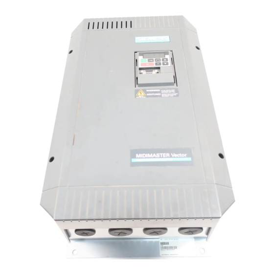
MIDIMASTER Vector
© Siemens plc 1999
Operating Instructions
Contents
SAFETY INSTRUCTIONS ............................................................... 4
1. OVERVIEW .............................................................................. 6
2. INSTALLATION - MICROMASTER Vector........................... 12
3. INSTALLATION - MIDIMASTER Vector ............................... 25
4. CONTROLS AND BASIC OPERATION ................................ 32
5. OPERATING MODES ............................................................ 36
6. SYSTEM PARAMETERS....................................................... 41
7. FAULT AND WARNING CODES........................................... 65
8. SPECIFICATIONS.................................................................. 67
9. SUPPLEMENTARY INFORMATION ..................................... 73
G85139-H1751-U529-D1
4/8/99
Advertisement
Table of Contents

Related Manuals for Siemens MICROMASTER Vector


Summary of Contents for Siemens MICROMASTER Vector
-
Page 1: Table Of Contents
Operating Instructions Contents SAFETY INSTRUCTIONS ............... 4 1. OVERVIEW ................6 2. INSTALLATION - MICROMASTER Vector......12 3. INSTALLATION - MIDIMASTER Vector ....... 25 4. CONTROLS AND BASIC OPERATION ........ 32 5. OPERATING MODES ............36 6. SYSTEM PARAMETERS............41 7. - Page 2 2.2.3 Power and Motor Connections - Frame Size C 2.2.4 Control Connections 2.2.5 External Motor Thermal Overload Protection 2.2.6 Block Diagram – MICROMASTER Vector Installation – MIDIMASTER Vector Mechanical Installation Electrical Installation 3.2.1 Power and Motor Connections 3.2.2 Control Connections 3.2.3...
- Page 3 General Description 5.7.2 Hardware Set-up 5.7.3 Parameter Settings System Parameters Fault and Warning Codes Fault Codes Warning Codes Specifications Supplementary Information Application Example USS Status Codes Electro-Magnetic Compatibility (EMC) Environmental Aspects User's Parameter Settings © Siemens plc 1999 G85139-H1751-U529-D1 4/8/99...
-
Page 4: Safety Instructions
The following terminals can carry dangerous voltages even if the inverter is inoperative: The MICROMASTER Vector and MIDIMASTER Vector inverter series do not fall - the power supply terminals L/L1, N/L2 and L3 (MMV) - L1, under the scope of the Machinery Directive. However, the products have been L2, and L3 (MDV). - Page 5 When using the analogue input, the DIP switches must be correctly set and the analogue input type selected (P023) before enabling the analogue input with P006. If this is not done, the motor may start inadvertently. © Siemens plc 1999 G85139-H1751-U529-D1...
-
Page 6: Overview
1. OVERVIEW 1. OVERVIEW The MICROMASTER Vector (MMV) and MIDIMASTER Vector (MDV) are a standard range of inverters with sensorless vector capability suitable for controlling the speed of 3 phase motors. Various models are available, ranging from the compact 120 W MICROMASTER Vector up to the 75 kW MIDIMASTER Vector. -
Page 7: Installation - General Notes
3.1 = Specific heat of air at sea level. Note: The Plastic Material of the case can be degraded by oil or grease. Care should be taken to ensure that the mounting surface and fixings are thoroughly degreased before use. © Siemens plc 1999 G85139-H1751-U529-D1 4/8/99... -
Page 8: Wiring Guidelines To Minimise The Effects Of Emi
In particular, grounding of the system at the inverter, as described below, may prove effective. Figures 1.2.1-1.2.3 illustrate how an RFI suppression filter should be installed and connected to the MICROMASTER Vector. Ensure that all equipment in the cubicle is well earthed using short, thick earthing cable connected to a common star point or busbar. - Page 9 Fix motor and control cable screens securely to metal back plate using suitable clips. EARTH BRAID EARTH BRAID Figure 1.2.1: Wiring guidelines to minimise effects of EMI - MICROMASTER Vector Frame Size A MAINS POWER INPUT FOOTPRINT FILTER METAL BACK-PLATE CONTROL...
-
Page 10: Electrical Installation - General Notes
Fix motor and control cable screen securely to metal back plate using suitable clips. Figure 1.2.3: Wiring guidelines to minimise effects of EMI MICROMASTER Vector Frame Size C On no account must safety regulations be compromised when installing inverters! 1.3 Electrical Installation - General Notes 1.3.1 Operation with Unearthed (IT) Supplies... -
Page 11: Installation After A Period Of Storage
Refer to DA64 catalogue for further details. In any case, all inverters will operate at full specification with cable lengths up to 25m for screened cable or 50m for unscreened cables. © Siemens plc 1999 G85139-H1751-U529-D1 4/8/99... -
Page 12: Installation - Micromaster Vector
English 2. INSTALLATION – MICROMASTER Vector 2. INSTALLATION - MICROMASTER Vector 2.1 Mechanical Installation WARNING THIS EQUIPMENT MUST BE EARTHED. To guarantee safe operation of the equipment it must be installed and commissioned properly by qualified personnel in compliance with the warnings laid down in these operating instructions. - Page 13 2. INSTALLATION – MICROMASTER Vector English MICROMASTER Vector inverters must be secured to a suitable vertical surface by bolts, washers and nuts. Frame size A units need two bolts or can be DIN rail mounted. Frame size B and C units require four bolts.
- Page 14 MMV220 C = 215 x 185 x 195 204 232 174 MMV300 MMV400 MMV550 MMV750 * These units also available with built in filter e.g. MMV220/3F Figure 2.1.2: Mechanical Installation Diagram - MICROMASTER Vector © Siemens plc 1999 G85139-H1751-U529-D1 4/8/99...
-
Page 15: Electrical Installation
2.2 Electrical Installation Read the Wiring Guidelines given in section 1.2 before commencing installation. The electrical connectors on the MICROMASTER Vector are shown in Figure 2.2.1. Asynchronous and synchronous motors can be connected to the MICROMASTER Vector inverters either individually or in parallel. - Page 16 · Frame size C : lift and secure the gland plate and the fan housing to the inverter. 2.2.1 Power and Motor Connections - MICROMASTER Vector - Frame Size A Ensure that the power source supplies the correct voltage and is designed for the necessary current (see section 8). Ensure that the appropriate circuit breakers with the specified current rating are connected between the power supply and inverter (see section 8).
- Page 17 2. INSTALLATION – MICROMASTER Vector English Fit the earth braid strap, supplied with the unit, between the PE faston connector and the mounting surface. Ensure there is a good electrical connection between the mounting surface and the earth strap. Connect the power input directly to the power terminals L/L1 - N/L2 (1 phase) or L/L1, N/L2, L3 (3 phase), and earth (PE) as shown in Figure 2.2.1, using a 3-core cable for single phase units or a 4-core cable for three phase units.
- Page 18 English 2. INSTALLATION – MICROMASTER Vector 2.2.2 Power and Motor Connections - MICROMASTER Vector - Frame Size B The terminal arrangement for frame size B is similar to frame size A Refer to Figures 2.2.1 and 2.2.2 and proceed as follows: 1.
- Page 19 2. INSTALLATION – MICROMASTER Vector English Ensure that the power source supplies the correct voltage and is designed for the necessary current. Ensure that the appropriate circuit-breakers with the specified current rating are connected between the power supply and inverter see section 8.
- Page 20 English 2. INSTALLATION – MICROMASTER Vector 2.2.3 Power and Motor Connections - MICROMASTER Vector - Frame Size C Fan housing opening tab B & C: Gland plate release tabs Control cable input Mains cable input Motor cable output Braking resistor/ DC link cable input...
- Page 21 2. INSTALLATION – MICROMASTER Vector English The terminal arrangement for frame size C is similar to frame size A. Refer to Figures 2.2.1 and 2.2.3 and proceed as follows: 1. While supporting the fan housing with one hand, insert the blade of a screwdriver into slot A on the underside of the inverter and press upwards to release the securing tab.
-
Page 22: Control Connections
RS485 RS485 D-type (for USS protocol) Figure 2.2.4: Control Connections - MICROMASTER Vector Note: Do not use the internal RS485 connections (terminals 24 and 25) if you intend using the external RS485 connection on the front panel e.g. to connect a Clear Text Display (OPM2). -
Page 23: External Motor Thermal Overload Protection
2. INSTALLATION – MICROMASTER Vector English 2.2.5 External Motor Thermal Overload Protection When operated below rated speed, the cooling effect of fans fitted to the motor shaft is reduced. so that most motors require de-rating for continuous operation at low frequencies. To ensure that motors are protected against overheating under these conditions it is strongly recommended that a PTC temperature sensor is fitted to the motor and connected to the inverter control terminals as shown in Figure 2.2.5. -
Page 24: Block Diagram – Micromaster Vector
4 - 20 mA – 24 V RS485 DIN1 DIN2 B+/DC+ DIN3 DIN4 +15V AIN2/PID+ AIN2/PID - AOUT+ AOUT- Motor DIN5 DIP Switches DIN6 RS485 U, V, W Figure 2.2.6 Block Diagram - MICROMASTER Vector © Siemens plc 1999 G85139-H1751-U529-D1 4/8/99... -
Page 25: Installation - Midimaster Vector
The MIDIMASTER Vector must be secured to a suitable load-bearing wall by M8 bolts, washers and nuts. Frame size 4, 5 and 6 units need four bolts. Frame size 7 units should be lifted using the two lifting holes and secured by six bolts. Figure 3.1.1: MIDIMASTER Vector - Frame Size 4, 5, 6 and 7 © Siemens plc 1999 G85139-H1751-U529-D1 4/8/99... - Page 26 4 washers M8 Frame Sizes 4, 5 and 6 Depth D Æ Æ = 8.5 mm 6 bolts M8 6 nuts M8 6 washers M8 Frame Size 7 Figure 3.1.2: Mechanical Installation Diagram - MIDIMASTER Vector G85139-H1751-U529-D1 © Siemens plc 1999 4/8/99...
- Page 27 5 = 360 x 775 x 445 313 749 MDV4500/2 panel access door. MDV4500/3 6 = 360 x 875 x 505 313 849 MDV5500/3 7 = 500 x 1150 x 595 451 1122 MDV7500/3 Figure: 3.1.2 (continued) © Siemens plc 1999 G85139-H1751-U529-D1 4/8/99...
-
Page 28: Electrical Installation
FS6 units FS7 units FS6 units Control DIP switches terminals Note: Switch 6 not used FS4/5 units L1 L2 L3 PE PE DC- D C+ Power and Motor terminals Figure 3.2.1: MIDIMASTER Vector Connectors G85139-H1751-U529-D1 © Siemens plc 1999 4/8/99... -
Page 29: Power And Motor Connections
Note : If a synchronous motor is connected to the inverter, the motor current may be two and a half to three times greater than that expected so the inverter must be de-rated accordingly. © Siemens plc 1999 G85139-H1751-U529-D1 4/8/99... -
Page 30: Control Connections
When operated below rated speed, the cooling effect of fans fitted to the motor shaft is reduced. so that most motors require de-rating for continuous operation at low frequencies. For protection measures using a PTC see section 2.2.5. G85139-H1751-U529-D1 © Siemens plc 1999 4/8/99... -
Page 31: Block Diagram – Midimaster Vector
0 - 20 mA 4 - 20 mA – 24 V RS485 DIN1 DIN2 DIN3 DIN4 +15V AIN2/PID+ AIN2/PID - A1OUT+ AOUT- Motor DIN5 DIP Switches DIN6 Note:Switch 6 not used) RS485 A2OUT+ AOUT- U, V, W © Siemens plc 1999 G85139-H1751-U529-D1 4/8/99... -
Page 32: Controls And Basic Operation
The five DIP selector switches have to be set in agreement with P023 or P323 according to the operation of the inverter. Figure 4.1.2 below, shows the settings of the switches for the different modes of operation. G85139-H1751-U529-D1 © Siemens plc 1999 4/8/99... -
Page 33: Dip Selector Switches
2 V to 10 V 0 to 20 mA -10 V to +10 V 4 to 20 mA 0 to 20 mA 4 to 20 mA Note: = ON position Figure 4.1.2. DIP Selector Switches © Siemens plc 1999 G85139-H1751-U529-D1 4/8/99... -
Page 34: Basic Operation
1.5 seconds while the inverter is stopped. The inverter is programmed at the factory for standard applications on Siemens standard motors. When using other motors it is necessary to enter the specifications from the motor's rating plate into parameters P080 to P085 (see Figure 4.2.1). Note: Access to these parameters is not possible unless P009 = 002 or 003. -
Page 35: Basic Operation – 10 Step Guide
The basic method of setting up the inverter for use is described below. This method uses a digital frequency setpoint and requires only the minimum number of parameters to be changed from their default settings. It assumes that a standard Siemens four-pole motor is connected to the inverter (see section 4.2.1 if another motor type is being used). -
Page 36: Operating Modes
5.3 Motor Control Modes The MICROMASTER Vector and MIDIMASTER Vector inverters have four different modes of operation which control the relationship between the voltage supplied by the inverter and the speed of the motor. The motor control mode of operation is selected at P077: ·... - Page 37 Input Motor Model Speed, Position and Torque feedback Figure 5.3.3 : MICROMASTER Vector sensorless Vector operation Although there is no position or speed feedback from the motor, the control system is a closed loop system because it compares the internal motor model performance with the desired performance. The system must therefore be carefully set up and stabilised for best performance.
-
Page 38: Stopping The Motor
SVC operating mode. For further information concerning SVC operation refer to Application Note “Sensorless Vector Control”, which may be obtained from or a Siemens Sales Office. http://www.siemens.com/micromaster Note: This mode gives the best flux control and higher torque. -
Page 39: Closed Loop Control
0/2 - 10 V or a 0/4 - 20 mA input signal (determined by the setting of the DIP selector switches 4 and 5 and P323), has 10-bit resolution and permits a differential (floating) input. 15 V dc power for the feedback transducer can be supplied from terminal 9 on the control block. © Siemens plc 1999 G85139-H1751-U529-D1 4/8/99... -
Page 40: G85139-H1751-U529-D1 © Siemens Plc
P220 Descriptions of all closed loop process control parameters are provided in section 6. For detailed information about PID operation, refer to the application note “Closed Loop Control”, which may be obtained from or a Siemens sales office. http://www.siemens.com/micromaster G85139-H1751-U529-D1 ©... -
Page 41: System Parameters
= 8). Press D or Ñ to change the value (all values between .00 and .99 are valid) and then press P twice to return to the parameter display. Resetting to Factory Defaults If parameters are changed accidentally, all parameters can be reset to their default values by setting parameter P944 to 1 and then pressing P. © Siemens plc 1999 G85139-H1751-U529-D1 4/8/99... -
Page 42: Fault Codes
MDV1100/2, 1500/2, 1850/2, 2200/2, [10.0] selected. 1500/3, 1850/3, 2200/3, 3000/3, Frequency 3700/3, 1500/4, 1850/4, 2200/4, 3000/4, 3700/4. MDV3000/2, 3700/2, 4500/2, 4500/3, [20.0] 5500/3, 7500/3. [40.0] 0 Hz Ramp down Time time (0 - 650 s) © Siemens plc 1999 G85139-H1751-U529-D1 4/8/99... - Page 43 3 = All parameters can be read/set. P010 · Display scaling 0 - 500.0 Scale factor for display when P001 = 0, 1, 4, 5, 7 or 9. [1.00] Four digit resolution. © Siemens plc 1999 G85139-H1751-U529-D1 4/8/99...
- Page 44 2 = Discontinuous smoothing. This provides a fast unsmoothed response to STOP commands and requests to reduce frequency. Note: P004 must be set to a value > 0.0 for this parameter to have any effect. © Siemens plc 1999 G85139-H1751-U529-D1 4/8/99...
- Page 45 1, 2 and 3 (see Figure 4.1.2) This can be set to a lower value than P021 to give an inverse relationship between analogue input and frequency output. i.e. P021 P022 P022 P021 V/ I Note: The output frequency is limited by values entered for P012/P013. © Siemens plc 1999 G85139-H1751-U529-D1 4/8/99...
- Page 46 Nominal motor RPM (P082) 6/106 Motor Max. overload current magnetising (P083 x P186 / 100) current 7/107 Motor torque Max. overload current producing i.e. accelerating torque current (P083 x P186 / 100) regenerative (centre zero) torque G85139-H1751-U529-D1 © Siemens plc 1999 4/8/99...
- Page 47 If one of the digital inputs is programmed to select jog ramp times, the corresponding digital input can be used to select the ramp time set by this parameter, instead of the normal Ramp-down time set by P003. © Siemens plc 1999 G85139-H1751-U529-D1 4/8/99...
- Page 48 Valid if P006 = 2 and P053 = 6 or 18, or P053-55=17 [15.00] P044 · Fixed frequency 4 (Hz) 0 - 650.00 Valid if P006 = 2 and P052 = 6 or 18 , or P053-55=17 [20.00] G85139-H1751-U529-D1 © Siemens plc 1999 4/8/99...
- Page 49 Þ Þ Þ Ü P050 = 5 Ü Þ Þ Ü P050 = 6 Ü Ü Ü Þ Ü Ü Ü Ü P050 = 7 Þ Fixed setpoints not inverted Ü Fixed setpoints inverted © Siemens plc 1999 G85139-H1751-U529-D1 4/8/99...
- Page 50 Only effective when P007 = 0. ** Not available on P051, P052 or P356. *** The motor must be stopped before downloading begins. Downloading takes approx. 30 seconds. **** Top left hand segment in display flashes G85139-H1751-U529-D1 © Siemens plc 1999 4/8/99...
- Page 51 Ensure any equipment connected to the relays will remain safe if the relays change state during parameterisation. P062 Selection relay output RL2. 0 - 13 Sets the relay function, output RL2 (terminals 21and 22) (refer to the table in P061). © Siemens plc 1999 G85139-H1751-U529-D1 4/8/99...
- Page 52 3 = 50% 4 = 100% (i.e. continuous) WARNING: Standard braking resistors for the MICROMASTER Vector are designed for the 5% duty cycle only. Do not select higher duty cycles unless suitably rated resistors are being used to handle the increased power dissipation.
- Page 53 If DC injection braking is enabled via a digital input then DC current is applied for as long as the digital input is high. This causes heating of the motor. © Siemens plc 1999 G85139-H1751-U529-D1 4/8/99...
- Page 54 MUST be greater than 40W (80W for 3 AC 400 V inverters) or the inverter will be damaged. Purpose made resistors are available to cater for all MICROMASTER Vector variants. WARNING: Take care if an alternative resistor is to be used as the pulsed voltage applied by the inverter can destroy ordinary resistors.
- Page 55 MMV550/3 MMV750/3 Model % of full load de-rating P076 =0 or 1 P076 =2 or 3 MDV550/2 MDV750/2 MDV1100/2 MDV1500/2 MDV1850/2 MDV2200/2 MDV750/3 MDV1100/3 MDV1500/3 MDV1850/3 MDV2200/3 MDV3000/3 MDV3700/3 MDV550/4 MDV750/4 MDV1100/4 MDV1500/4 MDV1850/4 © Siemens plc 1999 G85139-H1751-U529-D1 4/8/99...
- Page 56 If motor thermal protection is required, then an external PTC must be used and P087 = 1. If P087 = 1 and the PTC input goes high then the inverter will trip (fault code F004 displayed). G85139-H1751-U529-D1 © Siemens plc 1999 4/8/99...
- Page 57 Inverter power rating (kW/hp) 0.12- 75.00 Read-only parameter that indicates the power rating of the inverter in kW. e.g. [¶¶¶] 0.55 = 550 W Note: If P101 = 1 then the rating is displayed in hp. © Siemens plc 1999 G85139-H1751-U529-D1 4/8/99...
- Page 58 1 = MICROMASTER 2nd Generation (MM2) 2 = COMBI MASTER 3 = MIDIMASTER 4 = MICROMASTER Junior (MMJ) 5 = MICROMASTER 3rd Generation (MM3) 6 = MICROMASTER Vector (MMV) 7 = MIDIMASTER Vector (MDV) 8 = COMBIMASTER 2nd Generation. P113 Drive model 0 - 29 Read-only parameter;...
- Page 59 P211 · 0% setpoint 0.0 - 100.00 Value of P210 to be maintained for 0% setpoint. [0.0] P212 · 100% setpoint 0.0 - 100.00 Value of P210 to be maintained for 100% setpoint. [100.00] © Siemens plc 1999 G85139-H1751-U529-D1 4/8/99...
- Page 60 The setting should then be reduced slightly (approx. 30%) until stability is restored. See section 5.3.3 for further information. P700 P701 · Specific to PROFIBUS-DP. See PROFIBUS Handbook for further P702 details. Access only possible with P099 = 1 G85139-H1751-U529-D1 © Siemens plc 1999 4/8/99...
- Page 61 Read only. The last recorded warning is stored in this parameter until power is removed from the inverter. This can be cleared by using the D and Ñ buttons. See section 7.2 for explanation of warning codes © Siemens plc 1999 G85139-H1751-U529-D1 4/8/99...
- Page 62 EEPROM - this is approximately 50,000 write cycles. Exceeding this number of write cycles would result in corruption of the stored data and subsequent data loss. The number of read cycles are unlimited. G85139-H1751-U529-D1 © Siemens plc 1999 4/8/99...
-
Page 63: Fault And Warning Codes
Internal interface fault F105 Check that the ambient temperature is not too high. Inverter overtemperature (internal sensor) Check that the air inlet and outlet are not obstructed Check that the inverter’s integral fan is working © Siemens plc 1999 G85139-H1751-U529-D1 4/8/99... - Page 64 Check that P087 has not been set to 1 without a PTC being connected. 15V power supply - current limit Check Connections Auto re-start after fault (P018) is WARNING: The inverter may start at any time. pending Braking resistor - hot G85139-H1751-U529-D1 © Siemens plc 1999 4/8/99...
-
Page 65: Specifications
0.85 / 1.9 2.6 / 5.7 5.0 / 11.0 All 1 AC 230 V MICROMASTER Vector include integrated Class A filters. Optional external Class B filters are available (see section 9.3). 230 V 1/3 AC MICROMASTER Vector Inverters Order No. (6SE32..) -
Page 66: Specifications
English 8. SPECIFICATIONS 380 V - 480 V Three Phase MICROMASTER Vector Inverters with built-in Class A filter Order No. (6SE32..) 15-8DB50 17-3DB50 21-0DC50 21-3DC50 21-5DC50 Inverter model MMV220/3F MMV300/3F MMV400/3F MMV550/3F MMV750/3F Input voltage range 3 AC 380 V - 480 V +/-10% 2.2 / 3... -
Page 67: Specifications
420 x 1150 x 310 integrated filter IP56 / NEMA 4/12 500 x 1150 x 570 Weight (kg) IP21 / NEMA 1 55 0 55.5 56.5 IP20 / NEMA 1 with integrated filter IP56 / NEMA 4/12 © Siemens plc 1999 G85139-H1751-U529-D1 4/8/99... - Page 68 Weight (kg) IP21 / NEMA 1 57.0 58.5 IP20 / NEMA 1 with integrated filter IP56 / NEMA 4/12 Output current ratings are reduced by 10% when operating on mains supply voltages over 460V. G85139-H1751-U529-D1 © Siemens plc 1999 4/8/99...
- Page 69 275 x 650 x 285 (w x h x d) IP56 / NEMA 4/12 360 x 875 x 483 Weight (kg) IP21 / NEMA 1 27.5 28.0 28.5 IP56 / NEMA 4/12 50.0 52.0 54.0 © Siemens plc 1999 G85139-H1751-U529-D1 4/8/99...
- Page 70 See section 9.3 Comment: MICROMASTER Vector and MIDIMASTER Vector are designed for use worldwide and therefore for wide line supply voltage ranges (1/3-ph. 208 - 240 V AC ±10%; 3-ph. 380 - 500 V AC ±10%; 3-ph. 525 - 575V AC ±15%) For the voltage data, it should be noted that: the operating range of the drive inverter lies between the two specified voltage values - e.g.
- Page 71 Braking Unit (MDV only) RFI suppression filter IP20 / NEMA 1 Accessory kit (MMV.FSA only) Please contact your local Clear Text Display (OPM2) Siemens sales office for PROFIBUS Module (CB15) further details. CANbus Module (CB16) SIMOVIS software for control via PC...
-
Page 72: Application Example
The display flashes whenever a byte is received, thus giving a basic indication that a serial link connection is established. If ‘100’ flashes on the display continuously, this usually indicates a bus termination fault. G85139-H1751-U529-D1 © Siemens plc 1999 4/8/99... -
Page 73: Supplementary Information
This approach is only applicable to radio communication transmitting apparatus. The MICROMASTER Vector and MIDIMASTER Vector units do not have an intrinsic function until connected with other components (e.g. a motor). Therefore, the basic units are not allowed to be CE marked for compliance with the EMC directive. However, full details are provided below of the EMC performance characteristics of the products when they are installed in accordance with the wiring recommendations in section 1.2. - Page 74 2 kV power cables, 1 kV control Radio Frequency Electromagnetic Field IEC 1000-4-3 26-1000 MHz, 10 V/m Emission limits not applicable inside a plant where no other consumers are connected to the same electricity supply transformer. G85139-H1751-U529-D1 © Siemens plc 1999 4/8/99...
- Page 75 1 kV power cables, 0.5 kV control Note: The MICROMASTER Vector and MIDIMASTER Vector units are intended exclusively for professional applications. Therefore, they do not fall within the scope of the harmonics emissions specification EN 61000-3-2. © Siemens plc 1999...
-
Page 76: Environmental Aspects
The component parts can be re-cycled, disposed of in accordance with local requirements or returned to the manufacturer. Documentation This handbook is printed on chlorine-free paper which has been produced from managed sustainable forests. No solvents have been used in the printing or binding process. G85139-H1751-U529-D1 © Siemens plc 1999 4/8/99... -
Page 77: User's Parameter Settings
P045 P122 P928 P046 25.0 P123 P930 P047 30.0 P124 P931 P048 35.0 P125 P944 P049 40.0 P128 P947 P050 P131 P958 P051 P132 P963 P052 P133 P967 P053 P134 P968 P054 P135 P970 © Siemens plc 1999 G85139-H1751-U529-D1 4/8/99... - Page 78 English 9. SUPPLEMENTARY INFORMATION P971 G85139-H1751-U529-D1 © Siemens plc 1999 4/8/99...
- Page 79 Bereich Automatisierungs- und Antriebstechnik (A&D) Standard Drives Division Geschäftsgebiet Standard Drives Postfach 3269, D-91050 Erlangen Siemens House Varey Road Congleton CW12 1PH Bestell-Nr. 6SE3286-4AB66 Änderungen vorbehalten G85139-H1751-U529-D1 Specification subject to change without prior notice *6SE3286-4AB66* *H1751-U529-D1* © Siemens plc 1999 Printed in England...
Need help?
Do you have a question about the MICROMASTER Vector and is the answer not in the manual?
Questions and answers