Euroheat harmony 5 Installation And Servicing
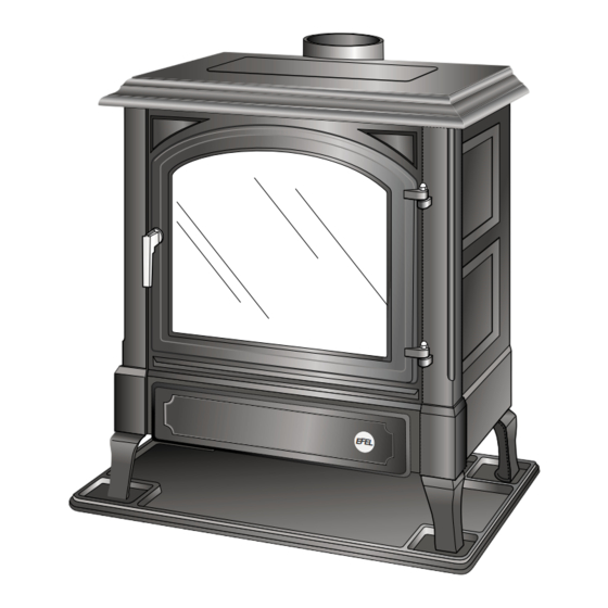
Gas balanced flue stove
Hide thumbs
Also See for harmony 5:
- Servicing instructions (17 pages) ,
- Installation instructions manual (14 pages) ,
- Installation & servicing (24 pages)
Table of Contents
Advertisement
Euroheat Distributors
(H.B.S.) Ltd.,
Unit 2, Court Farm
Business Park,
Bishops Frome,
Worcestershire,
WR6 5AY.
© Euroheat Distributors (H.B.S) Ltd. Dec 2004
Installation & Servicing
Harmony 5
Stanford 50
Gas Balanced Flue Stove
1
&
EFE L
Part No.
Serial Number
E & OE
Installation Servicing IN1045 Ed C
Advertisement
Table of Contents

Related Manuals for Euroheat harmony 5


Summary of Contents for Euroheat harmony 5
- Page 1 Gas Balanced Flue Stove EFE L Part No. Euroheat Distributors (H.B.S.) Ltd., Unit 2, Court Farm Serial Number Business Park, Bishops Frome, Worcestershire, WR6 5AY. © Euroheat Distributors (H.B.S) Ltd. Dec 2004 E & OE Installation Servicing IN1045 Ed C...
-
Page 2: Table Of Contents
Fitting the Electrical Connections Receiver location Information for Users which must be advised by the installer verbally or in writing. Removing Main Burner Jet Service Record E & OE © Euroheat Distributors (H.B.S) Ltd. Dec 2004 Installation Servicing IN1045 Ed C... -
Page 3: Safety Precautions
3: Under the base of the stove. 4: On the warranty registration form 5: On the warranty certificate returned to the user after successful registration. © Euroheat Distributors (H.B.S) Ltd. Dec 2004 E & OE Installation Servicing IN1045 Ed C... -
Page 4: Technical Data With Eurosit Gas Valve 630
Technical Data with Eurosit Gas Valve 630 Harmony 5 Gas and Stanford 50 Balanced Flue Model Number 49990 Heat Output Maximum 5 kW/hr (17060 BTU) Heat Output Minimum 1.9 kW/hr (6482 BTU) Gas Input Maximum 6 kW/hr (20472 BTU) Gas Input Minimum 2.5 kW/hr (8530 BTU) -
Page 5: Technical Data With Mertik Maxitrol Gv34 Gas Valve
Technical Data with Mertik Maxitrol GV34 Gas Valve Harmony 5 Stanford 50 Gas Balanced Flue Model Number 49990 Heat Output Maximum 5 kW/hr (17060 BTU) Heat Output Minimum 1.9 kW/hr (6482 BTU) Gas Input Maximum 6 kW/hr (20472 BTU) Gas Input Minimum 2.5 kW/hr (8530 BTU) -
Page 6: Primary Air Collar
Do not place furniture, furnishing or combustible objects within 1 metre of the stove. If any of these conditions are not fulfilled, DO NOT FIT THE STOVE until this has been rectified. E & OE © Euroheat Distributors (H.B.S) Ltd. Dec 2004 Installation Servicing IN1045 Ed C... -
Page 7: Hearth And Fireplace Requirements
12" 300mm 6" 150mm 1" 25mm 2" 50mm 2" 50mm 12" 300mm 6" 150mm © Euroheat Distributors (H.B.S) Ltd. Dec 2004 E & OE Installation Servicing IN1045 Ed C... -
Page 8: Standard Top To Horizontal Balnaced Flue Kit
Standard supply flue bend Telescopic module Telescopic module Stove adaptor Locking band Standard Top to Vertical Balanced Flue Kit (Part Number MS91060) Terminal Telescopic module Locking band E & OE © Euroheat Distributors (H.B.S) Ltd. Dec 2004 Installation Servicing IN1045 Ed C... -
Page 9: Balanced Flue Additional Flue Lengths, Elbows And Accessories
Terminal Guard Other Options Part Number Ceiling Support MS91056 FP767 Fire Stop Spacer MS91058 Roof Flashing MS91063 Existing Chimney Converter Kit to Balanced Flue MS91085 © Euroheat Distributors (H.B.S) Ltd. Dec 2004 E & OE Installation Servicing IN1045 Ed C... - Page 10 It is important to note that the balanced flue pipe must only ever rise vertically or travel horizontally at 90°. ����������������������� ��������������������� Add 1000mm to the measured horizontal length for each additional change of direction (each 90deg elbow) E & OE © Euroheat Distributors (H.B.S) Ltd. Dec 2004 Installation Servicing IN1045 Ed C...
-
Page 11: Example Horizontal To Vertical Ratio Calculations
flue will need the restricter Part Number 35432 fitted, which is part of the standard flue kit. ����������� © Euroheat Distributors (H.B.S) Ltd. Dec 2004 E & OE Installation Servicing IN1045 Ed C... -
Page 12: Vertical To Horizontal Ratio Graphs A & B
Length of horizontally run flue in millimetres 1000 4000 5000 2000 3000 6000 7000 4000 2000 1000 Choke Plate E & OE © Euroheat Distributors (H.B.S) Ltd. Dec 2004 Installation Servicing IN1045 Ed C... - Page 13 In this example there is sufficient vertical rise for the horizontal run. The vertical rise requires that the choke plate is fitted. (See page 11) © Euroheat Distributors (H.B.S) Ltd. Dec 2004 E & OE Installation Servicing IN1045 Ed C...
-
Page 14: Fitting The Flue Kit
It is your responsibility to ensure that no part of the flue installation contravenes any gas or building regulations. � E & OE © Euroheat Distributors (H.B.S) Ltd. Dec 2004 Installation Servicing IN1045 Ed C... -
Page 15: Position Of Flue Terminal On Outside Wall
Position of flue terminal on outside wall 12mm Flueing through combustible material ���������������������� ���� �������������������� ������������� �������������� ������������������ �������������� ������ ���������������� ���������������� ���������������������� ����� ������� © Euroheat Distributors (H.B.S) Ltd. Dec 2004 E & OE Installation Servicing IN1045 Ed C... -
Page 16: Balanced Flue Terminal Positions
1. An opening means a window or door that is able to be opened or a fixed opening such as an air vent. E & OE © Euroheat Distributors (H.B.S) Ltd. Dec 2004 Installation Servicing IN1045 Ed C... -
Page 17: Installation Of The Gas Supply, Bs 6891
Do not obstruct the area directly beneath the stove as this may block the passage of air into the appliance. If any of these conditions are not fulfilled, DO NOT FIT THE STOVE until the problem has been rectified. © Euroheat Distributors (H.B.S) Ltd. Dec 2004 E & OE Installation Servicing IN1045 Ed C... -
Page 18: Gas Connection
Turn off the gas, remove the pressure gauge and refit the test point screw, turn the gas supply on and check that test nipple is gas sound. E & OE © Euroheat Distributors (H.B.S) Ltd. Dec 2004 Installation Servicing IN1045 Ed C... -
Page 19: Fitting The Coal Effect Kit And Fuel Guard
fl ames. Small Coals 8 = Horse Shoe Coal 1,2,3,6,7 = Large coals 4, 5 & 9 Small Coals © Euroheat Distributors (H.B.S) Ltd. Dec 2004 E & OE Installation Servicing IN1045 Ed C... -
Page 20: Gas Control Valve
In the unlikely event of the flame being extinguished whilst the gas control is in the “on” position, immediately turn “off” and wait 2 minutes before attempting to relight. For full operating instructions see operation manual. E & OE © Euroheat Distributors (H.B.S) Ltd. Dec 2004 Installation Servicing IN1045 Ed C... -
Page 21: Thermostatic Eurosit Gas Valve 630 With Manual Override
Remove screw and ALTERED gently remove cover Low operation bypass. SHOULD NOT BE ALTERED Supply pressure Operating test nipple pressure test nipple Front Operating pressure adjustment © Euroheat Distributors (H.B.S) Ltd. Dec 2004 E & OE Installation Servicing IN1045 Ed C... -
Page 22: Lighting
Once the pilot has been established, let out the control knob and turn it anticlockwise to the “ON” position. Manual Control Turn the larger left hand control anti clockwise to increase, clockwise to decrease the desired heat output. E & OE © Euroheat Distributors (H.B.S) Ltd. Dec 2004 Installation Servicing IN1045 Ed C... -
Page 23: Mertik Maxitrol Gv34 Gas Valve
(The flat blade screw can be accessed through a hole in the bottom plate of the stove under the valve, anti clockwise to increase, clockwise to decrease.) © Euroheat Distributors (H.B.S) Ltd. Dec 2004 E & OE Installation Servicing IN1045 Ed C... -
Page 24: Gas Pressure Test Nipple Locations
2x larger connectors fit to the motor. Note these two connectors are different in size and fit only to the appropriate sized connector on the motor. Receiver location Place the receiver on the stove hearth under the gas valve. E & OE © Euroheat Distributors (H.B.S) Ltd. Dec 2004 Installation Servicing IN1045 Ed C... -
Page 25: Information For Users Which Must Be Advised By The Installer Verbally Or In Writing
Do not use the appliance if any of the coal effect components are broken. The appliance must be guarded to protect children, the aged or infirm. © Euroheat Distributors (H.B.S) Ltd. Dec 2004 E & OE Installation Servicing IN1045 Ed C... -
Page 26: Removing Main Burner Jet
Follow the procedure for the burner removal. Once the burner is removed the main jet can be replaced, ensure the sealing washers are fitted. Main Burner Jet When fitting main gas burner jet ensure sealing washers are fitted. E & OE © Euroheat Distributors (H.B.S) Ltd. Dec 2004 Installation Servicing IN1045 Ed C... - Page 27 For the latest editions of all Euroheat documentation visit our web site www.euroheat.co.uk. We would request that you inform Euroheat of information which you feel is not provided in this document which would assist other users in the future.
-
Page 28: Service Record
Locality Name ......................... Post Town ......................... When this form been County ..............completed contact Euroheat for Post Code ..............Telephone Number ............additional Service records E & OE © Euroheat Distributors (H.B.S) Ltd. Dec 2004 Installation Servicing IN1045 Ed C...
Need help?
Do you have a question about the harmony 5 and is the answer not in the manual?
Questions and answers