Table of Contents
Advertisement
Quick Links
Advertisement
Table of Contents

Related Manuals for Panasonic VDR-D210P


Summary of Contents for Panasonic VDR-D210P
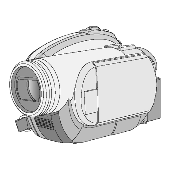
- Page 1 ORDER NO. MKE0701450CE Digital Video Camcorder VDR-D210P VDR-D220P VDR-D230P VDR-D210PC VDR-D220PC VDR-D230PC Vol. 1 Colours (S)....Silver Type © 2007 Panasonic Shikoku Electronics Co., Ltd. All rights reserved. Unauthorized copying distribution is a violation of law.
-
Page 2: Table Of Contents
VDR-D210P / VDR-D220P / VDR-D230P / VDR-D210PC / VDR-D220PC / VDR-D230PC CONTENTS Page Page 1 Safety Precautions 11 Voltage Chart of Connectors on Main P.C.B. 1.1. General Guidelines 12 Block Diagrams 2 Warning 13 Schematic Diagrams 2.1. Prevention of Electro Static Discharge (ESD) to 13.1. -
Page 3: Safety Precautions
VDR-D210P / VDR-D220P / VDR-D230P / VDR-D210PC / VDR-D220PC / VDR-D230PC 1 Safety Precautions 1.1. General Guidelines 1. IMPORTANT SAFETY NOTICE There are special components used in this equipment which are important for safety. These parts are marked by in the Schematic Diagrams, Circuit Board Layout, Exploded Views and Replacement Parts List. -
Page 4: Warning
VDR-D210P / VDR-D220P / VDR-D230P / VDR-D210PC / VDR-D220PC / VDR-D230PC 2 Warning 2.1. Prevention of Electro Static Discharge (ESD) to Electrostatically Sensitive (ES) Devices Some semiconductor (solid state) devices can be damaged easily by static electricity. Such components commonly are called Electrostatically Sensitive (ES) Devices. -
Page 5: How To Replace The Lithium Battery
“Disassembly and Assembly Instructions.") NOTE: This Lithium battery is a critical component. (Type No.: CGR-F/202AW Manufactured by Panasonic.) (Not supplied) It must never be subjected to excessive heat or discharge. It must therefore only be fitted in equipment designed specifically for its use. -
Page 6: Service Navigation
VDR-D210P / VDR-D220P / VDR-D230P / VDR-D210PC / VDR-D220PC / VDR-D230PC 3 Service Navigation 3.1. Introduction This service manual contains technical information which will allow service personnel´s to understand and service this model. Please place orders using the parts list and not the drawing reference numbers. -
Page 7: Specifications
VDR-D210P / VDR-D220P / VDR-D230P / VDR-D210PC / VDR-D220PC / VDR-D230PC 4 Specifications... -
Page 8: Service Mode
VDR-D210P / VDR-D220P / VDR-D230P / VDR-D210PC / VDR-D220PC / VDR-D230PC 5 Service Mode 5.1. Error Display "PUSH THE RESET SWITCH" is displayed automatically on the EVF or the LCD Monitor when an undesirable condition has occurred. Fig. 1 Note: When "PUSH THE RESET SWITCH"... - Page 9 VDR-D210P / VDR-D220P / VDR-D230P / VDR-D210PC / VDR-D220PC / VDR-D230PC Note: Only perform items 1, 3, and 4 in the Service Menu. To select the Item 1. Set to Service Menu. 2. Press [JOYSTICK CONTROL UP/DOWN] to select item [1], [3], or [4].
-
Page 10: Service Fixture & Tools
VDR-D210P / VDR-D220P / VDR-D230P / VDR-D210PC / VDR-D220PC / VDR-D230PC 6 Service Fixture & Tools 6.1. Service Fixture and Tools... -
Page 11: Service Position
VDR-D210P / VDR-D220P / VDR-D230P / VDR-D210PC / VDR-D220PC / VDR-D230PC 6.2. Service Position Caution Laser light striking the eye may cause your eyesight to be lost: For safety, be sure to remove any power supply (AC adaptor/charger, battery, etc.) from the DVD video camera/recorder before starting work. - Page 12 VDR-D210P / VDR-D220P / VDR-D230P / VDR-D210PC / VDR-D220PC / VDR-D230PC Fig. 3...
-
Page 13: Removal/Installation Of F.p.c. From Non Zif
VDR-D210P / VDR-D220P / VDR-D230P / VDR-D210PC / VDR-D220PC / VDR-D230PC 6.3. Removal/Installation of F.P.C. From Non ZIF (Zero Insertion Force) Connector Removal/Installation of F.P.C. from the Non ZIF (Zero Insertion Force) connector: 1. The Non ZIF connectors and the ZIF connectors are used on the unit. -
Page 14: Method For Ejecting The Dvd Tray Manually
VDR-D210P / VDR-D220P / VDR-D230P / VDR-D210PC / VDR-D220PC / VDR-D230PC 6.4. Method for Ejecting the DVD 6.5. EEPROM Data Tray Manually CAUTION: Be sure to save the EEPROM data using PC-EVR Caution Adjustment Program before service and adjustment in Laser light striking the eye may cause your eyesight order to make sure to avoid an accidental data loss, etc. -
Page 15: Special Note
VDR-D210P / VDR-D220P / VDR-D230P / VDR-D210PC / VDR-D220PC / VDR-D230PC 6.6. Special Note All integrated circuits and many other semiconductor devices are electrostatically sensitive and therefore require the special handlings techniques described under "ELECTROSTATICALLY SENSITIVE (ES) DEVICES" section of this service manual. -
Page 16: Disassembly And Assembly Instructions
VDR-D210P / VDR-D220P / VDR-D230P / VDR-D210PC / VDR-D220PC / VDR-D230PC 7 Disassembly and Assembly Instructions 7.1. Cabinet Section 7.1.1. DISASSEMBLY FLOWCHART Caution Laser light striking the eye may cause your eyesight to be lost: For safety, be sure to remove any power supply (AC adaptor/charger, battery, etc.) from the... -
Page 17: Disassembly Method
VDR-D210P / VDR-D220P / VDR-D230P / VDR-D210PC / VDR-D220PC / VDR-D230PC 7.1.2. Disassembly Method MAIN PARTS PORTION STEP Ref. Section NOTE PART REMOVE (518), (537), 2(519), 2(533), Front/Mic Ass'y FP6501, Hand Strap 2(518), 4(519), Side R & (537), FP81, LCD Ass'y... - Page 18 VDR-D210P / VDR-D220P / VDR-D230P / VDR-D210PC / VDR-D220PC / VDR-D230PC Note: MAIN PARTS SECTION 1. Parts with no Ref. No. in "EXPLODED VIEW" are not supplied. And some Ref. No. will be skipped. Be sure to make your orders of replacement parts according to the parts list.
- Page 19 VDR-D210P / VDR-D220P / VDR-D230P / VDR-D210PC / VDR-D220PC / VDR-D230PC FRONT/HOOD PORTION STEP Ref. Section PART REMOVE NOTE Front P.C.B. 3(537), FP6502 (For models with Light) 2(537), (54) LED Light F.P.C. (For models with Light) ----- LED Light Lens...
- Page 20 VDR-D210P / VDR-D220P / VDR-D230P / VDR-D210PC / VDR-D220PC / VDR-D230PC FRONT HOOD AND FRONT P.C.B. SECTION Note: 1. Parts with no Ref. No. in "EXPLODED VIEW" are not supplied. And some Ref. No. will be skipped. Be sure to make your orders of replacement parts according to the parts list.
- Page 21 VDR-D210P / VDR-D220P / VDR-D230P / VDR-D210PC / VDR-D220PC / VDR-D230PC SIDE R OPERATION PORTION LCD PORTION STEP Ref. Section STEP Ref. Section NOTE PART REMOVE NOTE PART REMOVE Side R P.C.B. LCD Protector (533) 2(537), P6301 LCD Case A Unit...
- Page 22 VDR-D210P / VDR-D220P / VDR-D230P / VDR-D210PC / VDR-D220PC / VDR-D230PC Note: SIDE R OPERATION AND LCD SECTION 1. Parts with no Ref. No. in "EXPLODED VIEW" are not supplied. And some Ref. No. will be skipped. Be sure to make your orders of replacement parts according to the parts list.
- Page 23 VDR-D210P / VDR-D220P / VDR-D230P / VDR-D210PC / VDR-D220PC / VDR-D230PC CCD & LENS PORTION STEP Ref. Section NOTE PART REMOVE CCD P.C.B. 2(536) Filter Rubber ----- Optical Filter ----- STEP Ref. Section NOTE PART REMOVE 2(538), Zoom Motor Unit...
- Page 24 VDR-D210P / VDR-D220P / VDR-D230P / VDR-D210PC / VDR-D220PC / VDR-D230PC CCD AND LENS SECTION Note: 1. Parts with no Ref. No. in "EXPLODED VIEW" are not supplied. And some Ref. No. will be skipped. Be sure to make your orders of replacement parts according to the parts list.
- Page 25 VDR-D210P / VDR-D220P / VDR-D230P / VDR-D210PC / VDR-D220PC / VDR-D230PC GRIP COVER & EVF PORTION STEP Ref. Section NOTE PART REMOVE EVF Angle Unit 2(537), (L-1) ----- Grip Cover Unit STEP Ref. Section NOTE PART REMOVE (533) Shoe Angle...
- Page 26 VDR-D210P / VDR-D220P / VDR-D230P / VDR-D210PC / VDR-D220PC / VDR-D230PC Note: GRIP COVER AND EVF SECTION 1. Parts with no Ref. No. in "EXPLODED VIEW" are not supplied. And some Ref. No. will be skipped. Be sure to make your orders of replacement parts according to the parts list.
- Page 27 VDR-D210P / VDR-D220P / VDR-D230P / VDR-D210PC / VDR-D220PC / VDR-D230PC Notes in chart 3. Removal of Rear Case Unit 1. Removal of Top Cover Unit 1) Open the LCD and Jack Cover to remove the 6 Screws 1) Remove the Screw (537) and remove the Disc Eject Cover.
- Page 28 VDR-D210P / VDR-D220P / VDR-D230P / VDR-D210PC / VDR-D220PC / VDR-D230PC 5. Removal of Bottom Ass'y 7. Removal of Main P.C.B. 1) Remove the 3 Screws (519). 1) Remove the 3 Screws (519). 2) Remove the Bottom Ass'y to disconnect Connector 2) Disconnect the Zoom Switch F.P.C.
- Page 29 VDR-D210P / VDR-D220P / VDR-D230P / VDR-D210PC / VDR-D220PC / VDR-D230PC 8. DVD Drive Frame Unit Caution Removal of DVD Drive Frame Unit & Disc Cover Lock Unit Caution 1) Remove the 2 Screws (540) and remove the Earth Laser light striking the eye may cause your eyesight Plate.
- Page 30 VDR-D210P / VDR-D220P / VDR-D230P / VDR-D210PC / VDR-D220PC / VDR-D230PC 9. Installation of Front P.C.B. 10. Removal of Side R P.C.B. 1) Install the Front P.C.B. with the 3 bosses, and tighten 1) Remove the 2 Screws (537). the 3 Screws (537).
- Page 31 VDR-D210P / VDR-D220P / VDR-D230P / VDR-D210PC / VDR-D220PC / VDR-D230PC 11. Removal of LCD Case B Unit, LCD Case A Unit 12. Installation of LCD Backlight P.C.B., LCD Panel Ass'y, Take care not to damage the F.P.C. LCD Shield Case and LCD Case B 1) Remove the Screw (533).
- Page 32 VDR-D210P / VDR-D220P / VDR-D230P / VDR-D210PC / VDR-D220PC / VDR-D230PC 13. Installation of LCD Panel, Reflect Sheet, Lead Light Reflect Sheet Panel, Diffusion Sheet, BEF Sheet, BEF Sheet A and Panel Holder Unit a. When replacing the LCD Panel, the Diffusion Sheet, the BEF Sheet and the BEF Sheet A, make sure to remove the Protection Sheets.
- Page 33 VDR-D210P / VDR-D220P / VDR-D230P / VDR-D210PC / VDR-D220PC / VDR-D230PC 14. Removal of CCD P.C.B., Filter Rubber and Optical Filter 16. Installation of Grip Cover Unit CAUTION: 1) Install the Grip Cover Unit with the 3 pins. 1) When removing the CCD P.C.B., take care that the 2) Tighten the 2 Screws (537).
- Page 34 VDR-D210P / VDR-D220P / VDR-D230P / VDR-D210PC / VDR-D220PC / VDR-D230PC 17. Installation of EVF F.P.C., EVF Lock Plate, EVF Slide 18. Removal of Eye Cap Base and Shoe Angle Remove the Eye Cap after removing the 2 Screws (533).
-
Page 35: Measurements And Adjustments
VDR-D210P / VDR-D220P / VDR-D230P / VDR-D210PC / VDR-D220PC / VDR-D230PC 8 Measurements and Adjustments 8.1. Electrical Adjustment 8.1.1. Initial Guideline The table below shows which adjustments are necessary according to the unit parts and individual parts to be replaced. Make sure... - Page 36 VDR-D210P / VDR-D220P / VDR-D230P / VDR-D210PC / VDR-D220PC / VDR-D230PC 8.1.2. Installation of USB-SERIAL driver 6. When EEPROM data has been saved, the menu will appear. Execute the "Setup.exe" file in "ComMass" folder by double To perform each adjustment, display the adjustment menu clicking to install the USB-SERIAL driver.
-
Page 37: Maintenance
VDR-D210P / VDR-D220P / VDR-D230P / VDR-D210PC / VDR-D220PC / VDR-D230PC 9 Maintenance 9.1. Cleaning Lens, Viewfinder and LCD Panel Do not touch the surface of the lens, Viewfinder and LCD Panel with your hand. When cleaning the lens, use air-blower to blow off the dust. - Page 38 VDR-D210P / VDR-D220P / VDR-D230P / VDR-D210PC / VDR-D220PC / VDR-D230PC...
-
Page 39: Troubleshooting
VDR-D210P / VDR-D220P / VDR-D230P / VDR-D210PC / VDR-D220PC / VDR-D230PC 10 Troubleshooting VIDEO No picture on both EVF and LCD in Camera Mode Check CCD Unit. Check Connection of CCD FPC (FP31). Re-Insert CCD FPC. Check the waveform of Pin 3, 4, 5, 6, 10, 12, and 13 of FP31 on Main P.C.B. - Page 40 VDR-D210P / VDR-D220P / VDR-D230P / VDR-D210PC / VDR-D220PC / VDR-D230PC No picture on EVF but LCD is normal Check Connection of EVF FPC (FP91). Re-Insert EVF FPC. Check the OPEN/CLOSE Switch on Side R Shaft Replace Side R Shaft Unit.
- Page 41 VDR-D210P / VDR-D220P / VDR-D230P / VDR-D210PC / VDR-D220PC / VDR-D230PC No picture on Video Output Jack Check Connection of B51 on Main P.C.B. Re-Insert Connector B51. Check the voltage of Pin 13 of B51 on Main P.C.B. Replace Main P.C.B.
- Page 42 VDR-D210P / VDR-D220P / VDR-D230P / VDR-D210PC / VDR-D220PC / VDR-D230PC AUDIO No Audio in Camera Mode Check Connection of B51 on Main P.C.B. Re-Insert Connector B51. Check Pin 32 and 34 of B51 (AUDIO_L/R) Pin 32 (AUDIO_R): 0.1V Pin 34 (AUDIO_L): 0.1V Repair Bottom P.C.B.
- Page 43 VDR-D210P / VDR-D220P / VDR-D230P / VDR-D210PC / VDR-D220PC / VDR-D230PC POWER No power Does unit turn on the power with SD Card mode or Check DVD Drive Unit. forced power on function ? <How to turn on with forced power on function>...
- Page 44 VDR-D210P / VDR-D220P / VDR-D230P / VDR-D210PC / VDR-D220PC / VDR-D230PC SYSCON Mechanism & Lens Motor lock code is displayed in Service Menu (Refer to "Service Menu.") Zoom Motor Lock (Zoom does not work) Replace Side L Unit. Check Zoom Switch.
- Page 45 VDR-D210P / VDR-D220P / VDR-D230P / VDR-D210PC / VDR-D220PC / VDR-D230PC Focus Motor Lock (Focus does not work) Check Connection of Lens FPC (FP71) on Main Re-Insert Lens FPC. P.C.B. Check waveform of Pin 9 and 10 of FP71 on Main P.C.B.
- Page 46 VDR-D210P / VDR-D220P / VDR-D230P / VDR-D210PC / VDR-D220PC / VDR-D230PC Operation Key does not work Check voltage of Pin 24 of FP61 on Main P.C.B. Replace Main P.C.B. Pin 24 (MODE_VDD): 2.8V Replace Side L Operation Unit. Check Key operation.
- Page 47 VDR-D210P / VDR-D220P / VDR-D230P / VDR-D210PC / VDR-D220PC / VDR-D230PC DVD DRIVE UNIT How to confirm which there is malfunction in Main P.C.B. or DVD Drive Unit. Does a power turn on with Disc REC or PLAY When install normal Disc, any error message...
-
Page 48: Voltage Chart Of Connectors On Main P.c.b
VDR-D210P / VDR-D220P / VDR-D230P / VDR-D210PC / VDR-D220PC / VDR-D230PC 11 Voltage Chart of Connectors on Main P.C.B. MAIN P.C.B. MODE MODE MODE MODE MODE MODE MODE PIN NO. PIN NO. PIN NO. PIN NO. PIN NO. PIN NO. -
Page 49: Block Diagrams
VDR-D210P / VDR-D220P / VDR-D230P / VDR-D210PC / VDR-D220PC / VDR-D230PC 12 Block Diagrams OVERALL BLOCK DIAGRAM REAR UNIT MAIN P.C.B. IC1001, ETC SIDE L/OPERATION UNIT IC6004 IC6001 BATTERY FP11 TERMINAL EEPROM SERIAL DATA/CLOCK +3.3V EEPROM FP61 UNREG AUTO FOCUS SW... - Page 50 VDR-D210P / VDR-D220P / VDR-D230P / VDR-D210PC / VDR-D220PC / VDR-D230PC...
-
Page 51: Schematic Diagrams
VDR-D210P / VDR-D220P / VDR-D230P / VDR-D210PC / VDR-D220PC / VDR-D230PC 13 Schematic Diagrams 13.1. SCHEMATIC DIAGRAM & CIRCUIT BOARD LAYOUT NOTES 1. Important safety notice 3. Parts marked "PT" are not used in any models included in this service model. -
Page 52: Front Schematic Diagram
VDR-D210P / VDR-D220P / VDR-D230P / VDR-D210PC / VDR-D220PC / VDR-D230PC 13.2. FRONT SCHEMATIC DIAGRAM NOTE: For placing a purchase order of the parts, NOTE: NOTE: FRONT SCHEMATIC DIAGRAM be sure to use the part number listed in the parts list. -
Page 53: Bottom Schematic Diagram
VDR-D210P / VDR-D220P / VDR-D230P / VDR-D210PC / VDR-D220PC / VDR-D230PC 13.3. BOTTOM SCHEMATIC DIAGRAM BOTTOM SCHEMATIC DIAGRAM IMPORTANT SAFETY NOTICE: NOTE: For placing a purchase order of the parts, NOTE: NOTE: COMPONENTS IDENTIFIED BY THE SIGN HAVE be sure to use the part number listed in the parts list. -
Page 54: Lcd Backlight Schematic Diagram
VDR-D210P / VDR-D220P / VDR-D230P / VDR-D210PC / VDR-D220PC / VDR-D230PC 13.4. LCD BACKLIGHT SCHEMATIC DIAGRAM NOTE: NOTE: For placing a purchase order of the parts, NOTE: NOTE: LCD BACKLIGHT SCHEMATIC DIAGRAM ALL INDIVIDUAL PARTS EXCEPT D8101, D8103, D8105, AND D8107 be sure to use the part number listed in the parts list. -
Page 55: Side R / Evf Fpc / Evf Backlight / Led Light Schematic Diagrams
VDR-D210P / VDR-D220P / VDR-D230P / VDR-D210PC / VDR-D220PC / VDR-D230PC 13.5. SIDE R / EVF FPC / EVF BACKLIGHT / LED LIGHT SCHEMATIC DIAGRAMS NOTE: For placing a purchase order of the parts, NOTE: NOTE: be sure to use the part number listed in the parts list. -
Page 56: Ccd / Rear Case / Lcd Sw Schematic Diagrams
VDR-D210P / VDR-D220P / VDR-D230P / VDR-D210PC / VDR-D220PC / VDR-D230PC 13.6. CCD / REAR CASE / LCD SW SCHEMATIC DIAGRAMS NOTE: For placing a purchase order of the parts, NOTE: NOTE: be sure to use the part number listed in the parts list. -
Page 57: Side L/Operation / Disk Cover Lock Schematic
VDR-D210P / VDR-D220P / VDR-D230P / VDR-D210PC / VDR-D220PC / VDR-D230PC 13.7. SIDE L/OPERATION / DISK COVER LOCK SCHEMATIC DIAGRAMS NOTE: For placing a purchase order of the parts, NOTE: NOTE: be sure to use the part number listed in the parts list. -
Page 58: Interconnection Schematic Diagram
VDR-D210P / VDR-D220P / VDR-D230P / VDR-D210PC / VDR-D220PC / VDR-D230PC 13.8. INTERCONNECTION SCHEMATIC DIAGRAM NOTE: For placing a purchase order of the parts, NOTE: NOTE: INTERCONNECTION SCHEMATIC DIAGRAM be sure to use the part number listed in the parts list. -
Page 59: Printed Circuit Board
VDR-D210P / VDR-D220P / VDR-D230P / VDR-D210PC / VDR-D220PC / VDR-D230PC 14 Printed Circuit Board 14.1. FRONT P.C.B. NOTE: FRONT P.C.B. LSEP8375A1 (A,B) / LSEP8375B1 (C,D,E,F) NOTE: COMPARISON CHART OF MODELS & MARKS CIRCUIT BOARD LAYOUT SHOWS COMPONENTS INSTALLED FOR VARIOUS MODELS. -
Page 60: Bottom P.c.b
VDR-D210P / VDR-D220P / VDR-D230P / VDR-D210PC / VDR-D220PC / VDR-D230PC 14.2. BOTTOM P.C.B. BOTTOM P.C.B. LSEP8376C1 (A,B) / LSEP8376A1 (C,D,E,F) COMPARISON CHART IMPORTANT SAFETY NOTICE: OF MODELS & MARKS NOTE: COMPONENTS IDENTIFIED BY THE SIGN HAVE FOR SCHEMATIC DIAGRAM AND CIRCUIT BOARD LAYOUT NOTES,... -
Page 61: Lcd Backlight P.c.b
VDR-D210P / VDR-D220P / VDR-D230P / VDR-D210PC / VDR-D220PC / VDR-D230PC 14.3. LCD BACKLIGHT P.C.B. LCD BACKLIGHT P.C.B. LSEP8367B1 NOTE: NOTE: NOTE: FOR SCHEMATIC DIAGRAM AND CIRCUIT BOARD LAYOUT NOTES, ALL INDIVIDUAL PARTS EXCEPT D8102, D8104, D8107, D8109 AND D8111 CIRCUIT BOARD LAYOUT SHOWS COMPONENTS INSTALLED FOR VARIOUS MODELS. -
Page 62: Side R P.c.b
VDR-D210P / VDR-D220P / VDR-D230P / VDR-D210PC / VDR-D220PC / VDR-D230PC 14.4. SIDE R P.C.B. NOTE: NOTE: SIDE R P.C.B. LSEP8377A1 NOTE: MULTILAYER P.C.B. CIRCUIT BOARD LAYOUT SHOWS COMPONENTS INSTALLED FOR VARIOUS MODELS. FOR SCHEMATIC DIAGRAM AND CIRCUIT BOARD LAYOUT NOTES, THIS P.C.B. -
Page 63: Exploded View
VDR-D210P / VDR-D220P / VDR-D230P / VDR-D210PC / VDR-D220PC / VDR-D230PC 15 Exploded View 15.1. MAIN PARTS SECTION Note: MAIN PARTS SECTION 1. Parts with no Ref. No. in "EXPLODED VIEW" are not supplied. And some Ref. No. will be skipped. Be sure to make your orders of replacement parts according to the parts list. -
Page 64: Front Hood And Front P.c.b. Section
VDR-D210P / VDR-D220P / VDR-D230P / VDR-D210PC / VDR-D220PC / VDR-D230PC 15.2. FRONT HOOD AND FRONT P.C.B. SECTION FRONT HOOD AND FRONT P.C.B. SECTION Note: 1. Parts with no Ref. No. in "EXPLODED VIEW" are not supplied. And some Ref. No. will be skipped. Be sure to make your orders of replacement parts according to the parts list. -
Page 65: Side R Operation And Lcd Section
VDR-D210P / VDR-D220P / VDR-D230P / VDR-D210PC / VDR-D220PC / VDR-D230PC 15.3. SIDE R OPERATION AND LCD SECTION Note: SIDE R OPERATION AND LCD SECTION 1. Parts with no Ref. No. in "EXPLODED VIEW" are not supplied. And some Ref. No. will be skipped. Be sure to make your orders of replacement parts according to the parts list. -
Page 66: Ccd And Lens Section
VDR-D210P / VDR-D220P / VDR-D230P / VDR-D210PC / VDR-D220PC / VDR-D230PC 15.4. CCD AND LENS SECTION CCD AND LENS SECTION Note: 1. Parts with no Ref. No. in "EXPLODED VIEW" are not supplied. And some Ref. No. will be skipped. Be sure to make your orders of replacement parts according to the parts list. -
Page 67: Grip Cover And Evf Section
VDR-D210P / VDR-D220P / VDR-D230P / VDR-D210PC / VDR-D220PC / VDR-D230PC 15.5. GRIP COVER AND EVF SECTION Note: GRIP COVER AND EVF SECTION 1. Parts with no Ref. No. in "EXPLODED VIEW" are not supplied. And some Ref. No. will be skipped. Be sure to make your orders of replacement parts according to the parts list. -
Page 68: Packing Parts And Accessories Section
VDR-D210P / VDR-D220P / VDR-D230P / VDR-D210PC / VDR-D220PC / VDR-D230PC 15.6. PACKING PARTS AND ACCESSORIES SECTION PACKING PARTS AND ACCESSORIES SECTION IMPORTANT SAFTY NOTICE: COMPONENTS IDENTIFIED BY THE SIGN HAVE SPECIAL CHARACTERISTICS IMPORTANT FOR SAFETY. COMPARISON CHART WHEN REPLACING ANY OF THESE COMPONENTS, OF MODELS &... -
Page 69: Replacement Parts Lists
VDR-D210P / VDR-D220P / VDR-D230P / VDR-D210PC / VDR-D220PC / VDR-D230PC 16 Replacement Parts Lists BEFORE REPLACING PARTS, READ THE FOLLOWING: RTL: Retention Time Limited This indicates that the retention time is limited for this item. 16.1. REPLACEMENT NOTES After the discontinuation of this item in production, it will no longer be available. -
Page 70: Mechanical Replacement Parts List
VDR-D210P / VDR-D220P / VDR-D230P / VDR-D210PC / VDR-D220PC / VDR-D230PC 16.2. MECHANICAL REPLACEMENT Ref. Part No. Part Name & Description Remarks PARTS LIST LSGL0505 LEAD LIGHT PANEL LSGL0511 DIFFUSION SHEET LSGL0506 REFLECT SHEET LSGL0443 BEF SHEET LSGL0444 BEF SHEET A... -
Page 71: Electrical Replacement Parts List
VDR-D210P / VDR-D220P / VDR-D230P / VDR-D210PC / VDR-D220PC / VDR-D230PC SERVICE FIXTURES AND TOOLS Ref. Part No. Part Name & Description Remarks Ref. Part No. Part Name & Description Remarks FP41 K1MN16A00077 CONNECTOR 16P LSVQ0028 PLIER FOR NON ZIF CONNECTOR... - Page 72 VDR-D210P / VDR-D220P / VDR-D230P / VDR-D210PC / VDR-D220PC / VDR-D230PC Ref. Part No. Part Name & Description Remarks Ref. Part No. Part Name & Description Remarks R7811 ERJ3GEYJ472V MGF CHIP 1/16W 4.7K R7023 ERJ3GEYJ220V MGF CHIP 1/16W 22 ( C,D,E,F )
- Page 73 VDR-D210P / VDR-D220P / VDR-D230P / VDR-D210PC / VDR-D220PC / VDR-D230PC 16.3.5. SIDE R P.C.B. 16.3.4. LIQUID CRYSTAL DISPLAY BACKLIGHT P.C.B.NR CAPACITORS Ref. Part No. Part Name & Description Remarks TRANSISTORS Ref. Part No. Part Name & Description Remarks C6301 F1H1H103A219 C CHIP 50V 0.01UF...
Need help?
Do you have a question about the VDR-D210P and is the answer not in the manual?
Questions and answers