Advertisement
Questions, problems, missing parts?
Amerisun customer service department at 1-800-791-9458 or visit Amerisuninc.com or e-mail
support@amerisuninc.com. For engine related problems, questions and warranty service call the engine
manufacturer 1-877-274-2214.
WARNING! Read and follow all safety rules and instructions in this manual before attempting to operate this
machine. Failure to comply with these instructions may result in personal injury. Save these instructions. This
unit is equipped with an internal combustion engine and may spark resulting in fire or explosion if used near
combustible material or fluid. Only use when the engine's exhaust system is equipped with a spark arrester
meeting applicable local or state laws (if any). The spark arrester shall be maintained in effective working
order by operator.
If you have questions or need technical support, call the
MODEL-DB7001
Advertisement
Table of Contents

Related Manuals for Power smart DB7001


Summary of Contents for Power smart DB7001
- Page 1 MODEL-DB7001 Questions, problems, missing parts? If you have questions or need technical support, call the Amerisun customer service department at 1-800-791-9458 or visit Amerisuninc.com or e-mail support@amerisuninc.com. For engine related problems, questions and warranty service call the engine manufacturer 1-877-274-2214.
-
Page 2: Table Of Contents
TABLE OF CONTENTS Safety ..........................3 Safety Symbols ......................... 6 Feature Idenfitication ......................7 ........................8 Box Contents Assembly ........................10 Preparing Youe Snow Thrower ..................13 Operation ........................14 Recommended Maintenance Schedule ................. 16 Troubleshooting ......................18 Warranty ........................19... -
Page 3: Safety
Safety... - Page 5 Never operate machine at high speeds on slippery surfaces. Look down and behind and use care when backing up.
-
Page 7: Feature Idenfitication
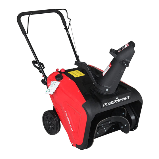
Feature Identification TECHNICAL SPECIFICATIONS TECHNICAL SPECIFICATIONS Clearing Wisth:21 inches Clearing Height:12.5 inches Engine Displacement:208cc,4stroke A- Auger Control D- Chute Handle E- Auger B- Chute Assembly C- Shave Plate For a complete parts breakdown go to www.amerisuninc.com... -
Page 8: Box Contents
BOX CONTENTS Check to ensure all of the following items are included: a. Snow Thrower (1) b. Chute Assembly (discharge chute, chute deflector and hardware, chute rotation handle and hardware) Located in Accessory Parts Bag: a. Oil funnel (1) b. Spark Plug wrench (1) c. - Page 9 1. Oversized Gas Cap Allows for easy opening and closing for more efficient refueling. 2. Primer Bulb The Primer Bulb system is designed to enrichen the fuel mixture for starting a cold engine. DO NOT over prime the fuel system. To properly use the Primer Bulb system, depress Primer Bulb 3 times maximum when starting a cold engine.
-
Page 10: Assembly
Assembly Control Cable Attachment Auger Control Control cable Installing the Upper Handle 2. Remove 2 knobs, bolts, and washers from lower handles. 3. Insert bolts going from the middle going out, then curved washer, and knob. Tighten firmly by hand. - Page 11 Chute Assembly 4. Remove bolt, washers and nuts from chute seat. 5. Place chute, and handle over discharge hole. Insert bolts from the inside through the holes, washers, then nuts. Wrench tighten.
- Page 12 7.Loosen the knobs on the top of the chute assembly and pivot the upper chute up or down to the desired angle. Tighten the knobs before operating the snow thrower. Chute handle 8. Use the chute handle to position the direction you want to throw the snow.
-
Page 13: Preparing Youe Snow Thrower
Use unleaded gasoline with 87 octane or higher Engine uses 16-18 ounces of oil,do not overfill. -
Page 14: Operation
Start 1. The choke switch position as shown picture (after the machine start the choke switch should be pulled to the left to the operation state) fig.1 Recoil handle fig.2 (Please refer to as bellow “PULL START PROCEDURE” ) PULL START PROCEDURE... - Page 15 Engaging the Drive Lift up slightly on the handle to allow the rubber paddles on the auger to contact the pavement and propel the snow thrower forward. Pushing downward on the handle will raise the augers off the ground and stop the forward motion. Note: Excessive upward pressure on the handle will result in premature wear on the rubber auger blades and is not covered by the warranty.
-
Page 16: Recommended Maintenance Schedule
Auger Control Cable Adjustment The auger cable is located on the left side(when standing behind the snow blower) and is made up of an upper and lower cable connected by an adjustment plate. The adjustment plate is located in-line with the cable below the control handle and is covered by a black plastic slip cover. The adjustment plate is used to adjust auger belt tension. -
Page 19: Warranty
TWO YEAR WARRANTY Amerisun Inc. and LCT Engine Corporation jointly warrant this product for two years against defects in material or workmanship when used for normal residential purposes. The manufacturer will, at its option, repair or replace, for the original purchaser, any part or parts which have been found to be defective in material and workmanship.
Need help?
Do you have a question about the DB7001 and is the answer not in the manual?
Questions and answers