KTM 125 SX Owner's Manual
Hide thumbs
Also See for 125 SX:
- Owner's manual (145 pages) ,
- Owner's handbook manual (45 pages) ,
- Owner's manual (135 pages)
Table of Contents

Related Manuals for KTM 125 SX


Summary of Contents for KTM 125 SX
- Page 1 OWNER'S MANUAL 2011 125 SX 150 SX 250 SX 150 XC USA 250 XC EU/USA 300 XC EU/USA Art. no. 3211596en...
- Page 3 KTM accepts no liability for delivery options, deviations from illustrations and descriptions, as well as misprints and other errors.
-
Page 4: Table Of Contents
TABLE OF CONTENTS Checking the riding sag of the shock absorber ....31 TABLE OF CONTENTS MEANS OF REPRESENTATION ..........4 Adjusting the spring preload of the shock absorber ..32 IMPORTANT INFORMATION ..........5 VIEW OF VEHICLE............... 7 Adjusting the riding sag .......... - Page 5 Removing the front wheel .......... 64 125 SX................. 94 Installing the front wheel ........... 64 Carburetor - basic setting for sandy surfaces (125 SX) ..94 Removing the rear wheel ........... 65 Carburetor configuration (125 SX)........95 Installing the rear wheel ..........
-
Page 6: Means Of Representation
All work marked with this symbol requires specialist knowledge and technical understanding. In the interest of your own safety, have these jobs done in an authorized KTM workshop! There, your motorcycle will be serviced optimally by specially trained experts using the specialist tools required. -
Page 7: Important Information
Warranty The work prescribed in the service schedule must be carried out in an authorized KTM workshop only and confirmed in the customer's service record, since otherwise no warranty claims will be honored. No warranty claims can be considered for damage resulting from manipulations and/or alterations to the vehicle. - Page 8 IMPORTANT INFORMATION Environment Motorcycling is a wonderful sport and we naturally hope that you can enjoy it to the full. However, it is a potential problem for the environment and can lead to conflicts with other persons. But if you use your motorcycle responsibly, you can ensure that such prob- lems and conflicts do not have to occur.
-
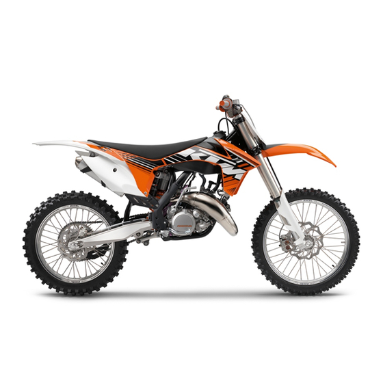
Page 9: View Of Vehicle
VIEW OF VEHICLE View of the vehicle from the left front (example) 601175-10 Hand brake lever ( p. 10) Kill switch ( p. 10) Clutch lever ( p. 10) Air filter box lid Fuel tap Choke ( p. 12) Shift lever ( p. -
Page 10: View Of The Vehicle From The Right Rear (Example)
VIEW OF VEHICLE View of the vehicle from the right rear (example) 601176-10 Seat Filler cap Handlebar cushion Throttle grip ( p. 10) Shock absorber, rebound adjustment Level viewer, rear brake fluid Shock absorber, compression adjustment Foot brake lever ( p. -
Page 11: Serial Numbers
SERIAL NUMBERS Chassis number The chassis number is stamped on the right side of the steering head. 601177-10 Type label The type label is fixed to the front of the steering head. 601177-11 Engine number The engine number is stamped on the left side of the engine under the engine ... -
Page 12: Controls
CONTROLS Clutch lever (All 125/150 models) The clutch lever is fitted on the left side of the handlebar. The clutch is hydraulically operated and self-adjusting. B00001-10 (All 250/300 models) The clutch lever is fitted on the left side of the handlebar. ... -
Page 13: Electric Starter Button (250/300 Xc)
CONTROLS Electric starter button (250/300 XC) The electric starter button is fitted on the right side of the handlebar. Possible states • Electric starter button in basic position pressed – In this position, the electric starter is actuated. • Electric starter button B00080-10 Opening the filler cap... -
Page 14: Fuel Tap (All Sx Models)
CONTROLS Fuel tap (All SX models) The fuel tap is on the left side of the fuel tank. With tap handle on the fuel tap, you can open or close the supply of fuel to the car- buretor. Possible states Fuel supply closed OFF –... -
Page 15: Kickstarter
CONTROLS (250 SX) The gear positions can be seen in the photograph. The neutral or idle position is between the first and second gears. B00005-11 Kickstarter 5.12 The kickstarter is fitted on the right side of the engine. The top part can be ... -
Page 16: Plug-In Stand (All Sx Models)
CONTROLS Plug-in stand (All SX models) 5.15 The holder for plug-in stand is on the left side of the wheel spindle. The plug-in stand is used to park the motorcycle. Info Remove the plug-in stand before riding. 100950-10... -
Page 17: Putting Into Operation
When using your motorcycle, remember that others may feel disturbed by excessive noise. – Make sure that the pre-delivery inspection work has been carried out by an authorized KTM workshop. You receive a delivery certificate and the service record at vehicle handover. -
Page 18: Running In The Engine
PUTTING INTO OPERATION Guideline Maximum permissible overall weight 335 kg (739 lb.) Maximum permissible front axle load 145 kg (320 lb.) Maximum permissible rear axle load 190 kg (419 lb.) – Check the spoke tension. ( p. 67) Info The spoke tension must be checked after riding the motorcycle for one half hour. –... -
Page 19: Preparations For Riding On Wet Sand
– Mount the dust cover for the air filter. Dust cover for air filter (59006019000) Info Read the KTM PowerParts installation instructions. B00435-01 – Mount the dust cover for the air filter for sand. Sand cover for air filter (59006022000) Info Read the KTM PowerParts installation instructions. -
Page 20: Preparations For Riding On Wet And Muddy Surfaces
Rain cover for air filter (59006021000) Info Follow the KTM PowerParts mounting instructions. – Adjust the carburetor jetting and setting. Info B00437-01 The recommended carburetor tuning is available from your authorized KTM workshop. – Mount the steel sprocket. – Clean the motorcycle. ( p. 83) –... -
Page 21: Preparations For Riding At High Temperatures And Low Speeds
Mount the rain cover for the air filter. Rain cover for air filter (59006021000) Info Follow the KTM PowerParts mounting instructions. – Adjust the carburetor jetting and setting. Info B00437-01 The recommended carburetor tuning is available from your authorized KTM workshop. -
Page 22: Riding Instructions
RIDING INSTRUCTIONS Checks and maintenance work when preparing for use Info Before riding the vehicle, always check its condition and operating safety. The vehicle must be in perfect technical condition when used. – Check the gear oil level. ( p. 80) –... -
Page 23: Starting Up
Do not change into a low gear at high engine speed. The engine races and the rear wheel can lock up. Info If you hear unusual noises while riding, stop immediately, switch off the engine and contact an authorized KTM workshop. First gear is used for starting off or for steep inclines. -
Page 24: Stopping, Parking
RIDING INSTRUCTIONS Stopping, parking Warning Risk of misappropriation Usage by unauthorized persons. – Never leave the vehicle while the engine is running. Secure the vehicle against use by unauthorized persons. Warning Danger of burns Some vehicle components become very hot when the vehicle is operated. –... - Page 25 RIDING INSTRUCTIONS – Fill the fuel tank with fuel up to measurement Guideline Measurement of 35 mm (1.38 in) Total fuel tank 7.5 l Super unleaded gasoline, mixed with capacity, approx. (1.98 US gal) 2-stroke engine oil (1:40) ( p.
-
Page 26: Service Schedule (Sx)
Final check: Check the vehicle for safe operation and take a test ride. • • • Make the service entry in KTM DEALER.NET and in the service record. • • • S10A: Every 10 service hours - corresponds to about 70 liters of fuel (18.5 US gal) / after every race S20A: Every 20 service hours - corresponds to about 140 liters of fuel (37 US gal) S30A: Every 30 service hours - corresponds to about 210 liters of fuel (55.5 US gal) -
Page 27: Maintenance Work (As An Additional Order)
SERVICE SCHEDULE (SX) Maintenance work (as an additional order) S20N S40A • Change the front brake fluid. Change the rear brake fluid. • Change the hydraulic clutch fluid. p. 54) • Grease the steering head bearing. p. 43) • Check/set the carburetor components. •... -
Page 28: Service Schedule (Xc)
Final check: Check the vehicle for safe operation and take a test ride. • • Make the service entry in KTM DEALER.NET and in the service record. • • S20A: Every 20 service hours - corresponds to about 140 liters of fuel (37 US gal) -
Page 29: Maintenance Work (As An Additional Order)
SERVICE SCHEDULE (XC) Maintenance work (as an additional order) S40A S80A • Change the front brake fluid. Change the rear brake fluid. • Change the foot brake cylinder seals. • Change the hydraulic clutch fluid. p. 54) • Grease the steering head bearing. p. -
Page 30: Tuning The Chassis
Caution Danger of accidents Disassembly of pressurized parts can lead to injury. – The shock absorber is filled with high density nitrogen. Adhere to the description provided. (Your authorized KTM workshop will be glad to help.) Info The low-speed setting can be seen during the slow to normal compression of the shock absorber. -
Page 31: Adjusting The High-Speed Compression Damping Of The Shock Absorber
Caution Danger of accidents Disassembly of pressurized parts can lead to injury. – The shock absorber is filled with high density nitrogen. Adhere to the description provided. (Your authorized KTM workshop will be glad to help.) Info The high-speed setting can be seen during the fast compression of the shock absorber. -
Page 32: Adjusting The Rebound Damping Of The Shock Absorber
10.5 Caution Danger of accidents Disassembly of pressurized parts can lead to injury. – The shock absorber is filled with high density nitrogen. Adhere to the description provided. (Your authorized KTM workshop will be glad to help.) – Turn adjusting screw clockwise with a screwdriver to the last click. -
Page 33: Measuring The Sag Of The Unloaded Rear Wheel
TUNING THE CHASSIS Info Turn clockwise to increase damping; turn counterclockwise to reduce damp- ing. Measuring the sag of the unloaded rear wheel 10.6 – Raise the motorcycle with the lift stand. ( p. 37) – Measure the distance – as vertical as possible – between the rear axle and a fixed point, for example, a mark on the side cover. -
Page 34: Adjusting The Spring Preload Of The Shock Absorber
Caution Danger of accidents Disassembly of pressurized parts can lead to injury. – The shock absorber is filled with high density nitrogen. Adhere to the description provided. (Your authorized KTM workshop will be glad to help.) Info Before changing the spring preload, make a note of the present setting, e.g., by measuring the length of the spring. -
Page 35: Checking The Basic Setting Of The Fork
TUNING THE CHASSIS Guideline Spring rate (125/150 SX) Weight of rider: 65… 75 kg (143… 60 N/mm (343 lb/in) 165 lb.) Weight of rider: 75… 85 kg (165… 63 N/mm (360 lb/in) 187 lb.) Weight of rider: 85… 95 kg (187… 66 N/mm (377 lb/in) 209 lb.) Spring rate (250 SX) -
Page 36: Adjusting The Compression Damping Of The Fork
TUNING THE CHASSIS Adjusting the compression damping of the fork 10.12 Info The hydraulic compression damping determines the fork suspension behavior. – Turn adjusting screws clockwise all the way. Info Adjusting screws are located at the top end of the fork legs. ... -
Page 37: Handlebar Position
TUNING THE CHASSIS Guideline Rebound damping (125/150 SX) Comfort 14 clicks Standard 12 clicks Sport 10 clicks Rebound damping (250 SX) Comfort 14 clicks Standard 12 clicks Sport 10 clicks Rebound damping (150 XC USA) Comfort 14 clicks Standard 12 clicks Sport 10 clicks Rebound damping (250/300 XC) - Page 38 TUNING THE CHASSIS – Position the handlebar. Info Make sure cables and wiring are positioned correctly. – Position the handlebar clamp. Mount and tighten screws Guideline Screw, handlebar clamp 20 Nm (14.8 lbf ft)
-
Page 39: Maintenance Work On The Chassis
MAINTENANCE WORK ON THE CHASSIS Raising the motorcycle with the lift stand 11.1 Note Danger of damage The parked vehicle may roll away or fall over. – Always place the vehicle on a firm and even surface. – Raise the motorcycle at the frame underneath the engine. Lift stand (54829055000) The wheels must no longer touch the ground. -
Page 40: Cleaning The Dust Boots Of The Fork Legs
MAINTENANCE WORK ON THE CHASSIS Cleaning the dust boots of the fork legs 11.4 – Raise the motorcycle with the lift stand. ( p. 37) – Loosen the fork protection. ( p. 38) – Push dust boots of both fork legs downwards. ... -
Page 41: Installing The Fork Legs
MAINTENANCE WORK ON THE CHASSIS – Unscrew screws . Take out the left fork leg. – Unscrew screws . Take out the right fork leg. B00021-10 Installing the fork legs 11.8 – Position the fork legs. Info The topmost milled groove in the fork leg must be flush to the upper edge of the upper triple clamp. -
Page 42: Installing The Fork Protector
MAINTENANCE WORK ON THE CHASSIS Installing the fork protector 11.10 – Position the fork protection on the left fork leg. Mount and tighten screws Guideline Remaining screws, chassis 10 Nm (7.4 lbf ft) – Position the fork protection on the right fork leg. Mount and tighten the screws. Guideline Remaining screws, chassis 10 Nm (7.4 lbf ft) - Page 43 MAINTENANCE WORK ON THE CHASSIS – Position the upper triple clamp with the steering. – Mount screw but do not tighten yet. – Install the CDI controller with screws Guideline Remaining screws, chassis 10 Nm (7.4 lbf ft) B00022-11 –...
-
Page 44: Checking The Play Of The Steering Head Bearing
Danger of accidents Unstable vehicle handling from incorrect steering head bearing play. – Adjust the steering head bearing play without delay. (Your authorized KTM workshop will be glad to help.) Info If the bike is ridden with play in the steering head bearing, the bearing and the bearing seats in the frame can become dam- aged over time. -
Page 45: Greasing The Steering Head Bearing
MAINTENANCE WORK ON THE CHASSIS Greasing the steering head bearing 11.15 – Remove the lower triple clamp. p. 40) – Install the lower triple clamp. p. 40) 800010-10 Removing the start number plate 11.16 – Remove screw and take off the clamp. ... -
Page 46: Removing The Shock Absorber
MAINTENANCE WORK ON THE CHASSIS Removing the shock absorber 11.20 – Raise the motorcycle with the lift stand. ( p. 37) – Remove screw and lower the rear wheel with the swing arm as far as possible without blocking the rear wheel. Fix the rear wheel in this position. –... -
Page 47: Removing The Air Filter Box Lid
MAINTENANCE WORK ON THE CHASSIS – Mount and tighten screw of the seat fixation. Guideline Remaining screws, chassis 10 Nm (7.4 lbf ft) 601192-10 Removing the air filter box lid 11.24 – Pull off the air filter box lid in area sideways and remove it toward the front. -
Page 48: Installing The Air Filter
MAINTENANCE WORK ON THE CHASSIS Installing the air filter 11.27 – Mount the clean air filter onto the air filter support. – Grease the air filter in area Long-life grease ( p. 115) 301262-10 – Put in both parts together, position them, and fix them with air filter holder ... -
Page 49: Installing The Main Silencer
MAINTENANCE WORK ON THE CHASSIS – Remove screws – Pull the main silencer off of the manifold at the rubber sleeve 601184-10 Installing the main silencer 11.30 – Mount the main silencer with rubber sleeve – Mount and tighten screws ... -
Page 50: Removing The Fuel Tank
MAINTENANCE WORK ON THE CHASSIS Removing the fuel tank 11.32 Danger Fire hazard Fuel is highly flammable. – Never refuel the vehicle near open flames or burning cigarettes, and always switch off the engine first. Be careful that no fuel is spilt, especially on hot vehicle components. Clean up spilt fuel immediately. –... -
Page 51: Checking The Chain For Dirt
MAINTENANCE WORK ON THE CHASSIS – Check the throttle cable routing. ( p. 53) – Position the fuel tank and fit the two spoilers to the sides of the radiator bracket. – Make sure that no cables are trapped or damaged. B00319-10 –... -
Page 52: Checking The Chain Tension
MAINTENANCE WORK ON THE CHASSIS – Clean the chain regularly and then treat with chain spray. Chain cleaner ( p. 115) Off-road chain spray ( p. 115) 400725-01 Checking the chain tension 11.36 Warning Danger of accidents Danger caused by incorrect chain tension. –... -
Page 53: Checking The Chain, Rear Sprocket, Engine Sprocket And Chain Guide
MAINTENANCE WORK ON THE CHASSIS – Loosen nut – Loosen nuts – Adjust the chain tension by turning the adjusting screws to the left and right. Guideline Chain tension 55… 58 mm (2.17… 2.28 in) Turn adjusting screws on the left and right so that the markings on the left ... - Page 54 MAINTENANCE WORK ON THE CHASSIS – Check the chain sliding guard for wear. » If the lower bolt edge of the chain is in line with or below the chain sliding guard: – Change the chain sliding guard. – Check the chain sliding guard for tightness. »...
-
Page 55: Adjusting The Chain Guide
MAINTENANCE WORK ON THE CHASSIS Adjusting the chain guide 11.39 – Unscrew screw . Remove screw . Swing the chain guide down. Condition Number of teeth: ≤ 44 teeth – Insert collar bushing in hole . Position the chain guide. ... -
Page 56: Checking The Fluid Level Of The Hydraulic Clutch
MAINTENANCE WORK ON THE CHASSIS (All 250/300 models) – Adjust the basic setting of the clutch lever to your hand size by turning adjust- ing screw Info Turn the adjusting screw counterclockwise to decrease the distance between the clutch lever and the handlebar. Turn the adjusting screw clockwise to increase the distance between the clutch lever and the handlebar. - Page 57 MAINTENANCE WORK ON THE CHASSIS (All 125/150 models) – Move the clutch fluid reservoir mounted on the handlebar to a horizontal posi- tion. – Remove screws – Remove cover with membrane 400245-10 – Fill bleeding syringe with the appropriate hydraulic fluid. ...
-
Page 58: Brakes
Danger of accidents Reduced braking efficiency due to worn brake disc(s). – Change the worn brake disc(s) without delay. (Your authorized KTM workshop will be glad to help.) – Check the thickness of the front and rear brake discs at several places on the disc to see if it conforms to measurement ... -
Page 59: Checking The Front Brake Fluid Level
Warning Danger of accidents Reduced braking effect caused by old brake fluid. – Change the brake fluid of the front and rear brake according to the service schedule. (Your authorized KTM workshop will be glad to help.) – Move the brake fluid reservoir mounted on the handlebar to a horizontal position. -
Page 60: Checking The Front Brake Linings
Warning Danger of accidents Reduced braking effect caused by old brake fluid. – Change the brake fluid of the front and rear brake according to the service schedule. (Your authorized KTM workshop will be glad to help.) Warning Danger of accidents Reduced braking efficiency due to oil or grease on the brake discs. - Page 61 Brake linings available from accessory suppliers are often not tested and approved for use on KTM vehicles. The construc- tion and friction factor of the brake linings and therefore the brake power can differ considerably from the original KTM brake linings. If brake linings are used that differ from the originals, there is no guarantee that they comply with the origi- nal license.
-
Page 62: Checking Free Travel Of Foot Brake Lever
BRAKES – Correct the brake fluid quantity to level Guideline Dimension (brake fluid level below 5 mm (0.2 in) top edge of container) Brake fluid DOT 4 / DOT 5.1 ( p. 113) – Position the cover with the membrane. Mount and tighten the screws. Info 100399-10 Clean up overflowed or spilt brake fluid immediately with water. -
Page 63: Checking The Rear Brake Fluid Level
Warning Danger of accidents Reduced braking effect caused by old brake fluid. – Change the brake fluid of the front and rear brake according to the service schedule. (Your authorized KTM workshop will be glad to help.) – Stand the vehicle upright. -
Page 64: Checking The Rear Brake Linings
Warning Danger of accidents Reduced braking effect caused by old brake fluid. – Change the brake fluid of the front and rear brake according to the service schedule. (Your authorized KTM workshop will be glad to help.) Warning Environmental hazard Hazardous substances cause environmental damage. - Page 65 BRAKES – Press the brake caliper toward the brake disc to push back the brake piston and ensure that no brake fluid runs out of the brake fluid reservoir, sucking it off if it does. Info Make sure when pushing back the brake piston that you do not press the brake caliper against the spokes.
-
Page 66: Wheels, Tires
WHEELS, TIRES Removing the front wheel 13.1 – Raise the motorcycle with the lift stand. ( p. 37) – Press the brake caliper onto the brake disc by hand in order to push back the brake pistons. Info Make sure when pushing back the brake pistons that you do not press the brake caliper against the spokes. -
Page 67: Removing The Rear Wheel
WHEELS, TIRES – Lift the front wheel into the fork, position it, and insert the wheel spindle. – Mount and tighten screw Guideline Screw, front wheel spindle M24x1.5 45 Nm (33.2 lbf ft) – Operate the hand brake lever several times until the brake linings are lying correctly against on the brake disc. -
Page 68: Checking The Tire Condition
13.5 Info Only mount tires approved and/or recommended by KTM. Other tires could have a negative effect on handling characteristics. The type, condition and air pressure of the tires all have an important impact on the handling characteristics of the motorcycle. -
Page 69: Checking The Tire Air Pressure
Danger of accidents Instable handling due to incorrect spoke tension. – Ensure that the spoke tension is correct. (Your authorized KTM workshop will be glad to help.) Info A loose spoke causes wheel imbalance and rapidly leads to more loose spokes. -
Page 70: Electrical System
– Do not discard batteries with the household trash. Dispose of a defective battery in an environmentally compatible manner. Give the battery to your KTM dealer or to a recycling center that accepts used batteries. Warning Environmental hazard Hazardous substances cause environmental damage. -
Page 71: Removing The Main Fuse (250/300 Xc)
ELECTRICAL SYSTEM Info Even when there is no load on the battery, it still loses power steadily. The charge state and the type of charge are very important for the service life of the battery. Rapid recharging with a high charging current shortens the battery's service life. If the charging current, charging voltage and charging time are exceeded, electrolyte escapes through the safety valves. -
Page 72: Installing The Main Fuse (250/300 Xc)
ELECTRICAL SYSTEM Installing the main fuse (250/300 XC) 14.5 Warning Fire hazard The electrical system can be overloaded by the use of incorrect fuses. – Use only fuses with the prescribed amperage. Never by-pass or repair fuses. – Insert the main fuse. Fuse (58011109110) Info A reserve fuse... -
Page 73: Cooling System
COOLING SYSTEM Cooling system 15.1 (All 125/150 models) Water pump in the engine circulates the coolant. The pressure resulting from the warming of the cooling system is regulated by a valve in radiator cap . This ensures that operating the vehicle at the specified ... -
Page 74: Installing The Radiator Cover (All Sx Models)
COOLING SYSTEM – Attach the radiator shield at holding lugs . Attach mounting points at the radi- ator. – Install the fuel tank. p. 48) 601203-10 Installing the radiator cover (All SX models) 15.4 – Remove the fuel tank. p. -
Page 75: Checking The Coolant Level
COOLING SYSTEM » If the level of the coolant does not meet specifications: – Correct the coolant level. Alternative 1 Coolant ( p. 113) Alternative 2 Coolant (mixed ready to use) ( p. 113) – Mount the radiator cap. Checking the coolant level 15.6 Warning Danger of scalding During motorcycle operation, the coolant gets very hot and is under pressure. -
Page 76: Refilling With Coolant
COOLING SYSTEM (All 125/150 models) – Remove screw . Remove radiator cap – Completely drain the coolant. – Mount screw with a new seal ring and tighten it. Guideline Drain plug, water pump cover M10x1 15 Nm (11.1 lbf ft) 601186-11 (All 250/300 models) -
Page 77: Tuning The Engine
TUNING THE ENGINE Checking the play in the throttle cable 16.1 – Move the handlebar to the straight-ahead position. – Push back bellows – Pull back the throttle cable casing until you sense a resistance. – Now check throttle cable play ... -
Page 78: Carburetor - Adjusting The Idle Speed
– Screw in idle air adjusting screw all the way and turn it to the specified basic position. Guideline Idle air adjusting screw (125 SX) Open 1.5 turns Idle air adjusting screw (150 SX) Open 2 turns Idle air adjusting screw (150 XC USA) -
Page 79: Emptying The Carburetor Float Chamber
TUNING THE ENGINE Emptying the carburetor float chamber 16.5 Danger Fire hazard Fuel is highly flammable. – Never refuel the vehicle near open flames or burning cigarettes, and always switch off the engine first. Be careful that no fuel is spilt, especially on hot vehicle components. Clean up spilt fuel immediately. –... -
Page 80: Changing The Ignition Curve
TUNING THE ENGINE Changing the ignition curve 16.7 Change the ignition curve from Performance to Soft. – Disconnect plug connection . (Figure 601190-10 p. 77) Soft – better rideability Change the ignition curve from Soft to Performance. – Connect plug connection . -
Page 81: Engine Characteristic - Adjust The Auxiliary Spring
TUNING THE ENGINE Engine characteristic - adjust the auxiliary spring (All 250/300 models) 16.11 Warning Danger of burns Some vehicle components become very hot when the vehicle is operated. – Do not touch hot components such as exhaust system, radiator, engine, shock absorber and brakes. Allow these compo- nents to cool down before starting work on them. -
Page 82: Maintenance Work On The Engine
MAINTENANCE WORK ON THE ENGINE Checking the gear oil level 17.1 Info The gear oil level must be checked when the engine is cold. – Stand the motorcycle upright on a horizontal surface. (All 125/150 models) – Remove gear oil level check screw ... -
Page 83: Draining The Gear Oil
MAINTENANCE WORK ON THE ENGINE Draining the gear oil 17.3 Warning Danger of scalding Engine oil and gear oil get very hot when the motorcycle is ridden. – Wear appropriate protective clothing and safety gloves. In case of burns, rinse immediately with lukewarm water. Warning Environmental hazard Hazardous substances cause environmental damage. -
Page 84: Adding Gear Oil
MAINTENANCE WORK ON THE ENGINE Danger Danger of poisoning Exhaust gases are poisonous and inhaling them may result in unconsciousness and/or death. – When running the engine, always make sure there is sufficient ventila- tion, and do not start or run the engine in an enclosed space without an effective exhaust extraction system. -
Page 85: Cleaning, Care
CLEANING, CARE Cleaning the motorcycle 18.1 Note Material damage Damage and destruction of components by high-pressure cleaning equipment. – Never clean the vehicle with high-pressure cleaning equipment or a strong water-jet. The excessive pressure can penetrate electri- cal components, socket connects, throttle cables, and bearings, etc., and can damage or destroy these parts. Warning Environmental hazard Hazardous substances cause environmental damage. -
Page 86: Storage
Check the tire air pressure. ( p. 67) – Store the vehicle in a dry location that is not subject to large fluctuations in temperature. Info KTM recommends raising the motorcycle. – Raise the motorcycle with the lift stand. ( p. 37) –... -
Page 87: Troubleshooting
TROUBLESHOOTING Faults Possible cause Action – The engine cannot be cranked (elec- Operating error Go through the steps of starting the engine. tric starter) p. 20) (250/300 XC) – Battery discharged Recharge the battery. p. 68) – Check the charging voltage. –... - Page 88 TROUBLESHOOTING Faults Possible cause Action Engine stalls or is popping into the Lack of fuel (All SX models) – carburetor of the fuel tap to the ON Turn handle position. (Figure 601185-10 p. 12) (All XC models) – of the fuel tap to the ON Turn handle ...
-
Page 89: Technical Data - Engine
TECHNICAL DATA - ENGINE 125 SX 21.1 Design 1-cylinder 2-stroke engine, water-cooled, with reed intake and exhaust control Displacement 124.8 cm³ (7.616 cu in) Stroke 54.5 mm (2.146 in) Bore 54 mm (2.13 in) Crankshaft bearing 1 grooved ball bearing/1 roller bearing... -
Page 90: 150 Xc Usa
TECHNICAL DATA - ENGINE 6th gear 22:24 Ignition Contactless controlled fully electronic ignition with digital igni- tion adjustment, type Kokusan Ignition point (BTDC) 1.4 mm (0.055 in) Spark plug NGK BR9 ECMVX Spark plug electrode gap 0.60 mm (0.0236 in) Starting aid Kickstarter 150 XC USA... -
Page 91: 250 Xc Eu/Usa
TECHNICAL DATA - ENGINE X (upper edge of piston to upper edge of cylinder) 0… 0.10 mm (0… 0.0039 in) Z (height of control flap) 48 mm (1.89 in) Primary transmission 26:72 Clutch Multidisc clutch in oil bath/hydraulically activated Gearbox 5-gear, claw shifted Transmission ratio 1st gear... -
Page 92: Xc Eu/Usa
TECHNICAL DATA - ENGINE 300 XC EU/USA 21.6 Design 1-cylinder 2-stroke engine, water-cooled, with reed intake and exhaust control Displacement 293 cm³ (17.88 cu in) Stroke 72 mm (2.83 in) Bore 72 mm (2.83 in) Exhaust valve - Beginning of adjustment 5,500 rpm Exhaust valve - end of adjustment with red auxiliary spring 7,300 rpm... -
Page 93: Technical Data - Engine Tightening Torques
TECHNICAL DATA - ENGINE TIGHTENING TORQUES All 125/150 models 22.1 ® Screw, membrane 2 Nm (1.5 lbf ft) Loctite 243™ ® Locking screw for bearing 6 Nm (4.4 lbf ft) Loctite 243™ – Screw, alternator cover 5 Nm (3.7 lbf ft) –... -
Page 94: 250/300 Xc
TECHNICAL DATA - ENGINE TIGHTENING TORQUES ® Screw, water pump wheel 6 Nm (4.4 lbf ft) Loctite 243™ – Screw, clutch cover 10 Nm (7.4 lbf ft) ® Screw, clutch slave cylinder 10 Nm (7.4 lbf ft) Loctite 243™ – Screw, clutch spring 10 Nm (7.4 lbf ft) ®... - Page 95 TECHNICAL DATA - ENGINE TIGHTENING TORQUES ® Screw, shift drum locating 10 Nm (7.4 lbf ft) Loctite 243™ ® Screw, shift lever 14 Nm (10.3 lbf ft) Loctite 243™ – Screw, starter motor 8 Nm (5.9 lbf ft) – Screw, water pump cover 10 Nm (7.4 lbf ft) –...
-
Page 96: Technical Data - Carburetor
Idling jet 42 (40, 45) Starting jet Idle air adjusting screw Open 1.5 turns Throttle slide 7 with cut-out Carburetor - basic setting for sandy surfaces (125 SX) 23.2 Idle air adjusting screw Open 1.5 turns Idling jet Jet needle NOZH... -
Page 97: Carburetor Configuration (125 Sx)
TECHNICAL DATA - CARBURETOR Carburetor configuration (125 SX) 23.3 400709-01 M/FT ASL Sea level TEMP Temperature Idle air adjusting screw is open Idling jet Needle Needle position from above Main jet 1... 5 Needle position from above The carburetor configuration depends on the defined ambient and operating conditions. -
Page 98: Carburetor - Basic Setting For Sandy Surfaces (150 Sx)
TECHNICAL DATA - CARBURETOR 150 SX 23.4 Carburetor type KEIHIN PWK 38S AG Carburetor identification number BC0_0 Needle position 2nd position from top Jet needle NOZI (NOZH, NOZJ) Main jet 182 (180, 185) Idling jet 40 (42) Starting jet Idle air adjusting screw Open 2 turns Throttle slide... -
Page 99: Carburetor Configuration (150 Sx)
TECHNICAL DATA - CARBURETOR Carburetor configuration (150 SX) 23.6 401037-01 M/FT ASL Sea level TEMP Temperature Idle air adjusting screw is open Idling jet Needle Needle position from above Main jet 1... 5 Needle position from above The carburetor configuration depends on the defined ambient and operating conditions. 0 0 1 0 0 2 Info... -
Page 100: Carburetor - Basic Setting For Sandy Surfaces (250 Sx)
TECHNICAL DATA - CARBURETOR 250 SX 23.7 Carburetor type KEIHIN PWK 36S AG Carburetor identification number FK0180 Needle position 3rd position from top Jet needle N1EI (N1EH, N1EJ) Main jet 158 (155, 160) Idling jet 42 (40) Starting jet Idle air adjusting screw Open 1.0 turn Throttle slide... -
Page 101: Carburetor Configuration (250 Sx)
TECHNICAL DATA - CARBURETOR Carburetor configuration (250 SX) 23.9 401038-01 M/FT ASL Sea level TEMP Temperature Idle air adjusting screw is open Idling jet Needle Needle position from above Main jet 1... 5 Needle position from above The carburetor configuration depends on the defined ambient and operating conditions. 0 0 1 0 0 2 Info... -
Page 102: 150 Xc Usa
TECHNICAL DATA - CARBURETOR 150 XC USA 23.10 Carburetor type KEIHIN PWK 36S AG Carburetor identification number BC1_0 Needle position 3rd position from top Jet needle NOZI (NOZH, NOZJ) Main jet 170 (168, 172) Idling jet 42 (40, 45) Starting jet Idle air adjusting screw Open 1.5 turns... -
Page 103: 250 Xc Eu/Usa
TECHNICAL DATA - CARBURETOR Needle position from above Main jet 1... 5 Needle position from above The carburetor configuration depends on the defined ambient and operating conditions. 0 0 1 0 0 2 Info 0 0 3 Not for sandy surfaces 0 0 4 0 0 5 B00075-10... -
Page 104: Carburetor Configuration (250 Xc Eu/Usa)
TECHNICAL DATA - CARBURETOR Carburetor configuration (250 XC EU/USA) 23.13 401040-01 M/FT ASL Sea level TEMP Temperature Idle air adjusting screw is open Idling jet Needle Needle position from above Main jet 1... 5 Needle position from above The carburetor configuration depends on the defined ambient and operating conditions. 0 0 1 0 0 2 Info... -
Page 105: 300 Xc Eu/Usa
TECHNICAL DATA - CARBURETOR 300 XC EU/USA 23.14 Carburetor type KEIHIN PWK 36S AG Carburetor identification number BC5_0 Needle position 4th position from top Jet needle N2ZK (N2ZJ, N2ZL) Main jet 165 (162) Idling jet Starting jet Idle air adjusting screw Open 2 turns Throttle slide... - Page 106 TECHNICAL DATA - CARBURETOR Needle position from above Main jet 1... 5 Needle position from above The carburetor configuration depends on the defined ambient and operating conditions. 0 0 1 0 0 2 Info 0 0 3 Not for sandy surfaces 0 0 4 0 0 5 B00075-10...
-
Page 107: Technical Data - Chassis
3.5 mm (0.138 in) Tire air pressure off road Front 1.0 bar (15 psi) Rear 1.0 bar (15 psi) Secondary ratio (125 SX, 150 XC USA) 13:50 Secondary ratio (250/300 XC, 150 SX) 14:50 Secondary ratio (250 SX) 13:48 Chain 5/8 x 1/4"... -
Page 108: Capacity - Fuel
TECHNICAL DATA - CHASSIS Capacity - fuel 24.2 Total fuel tank capacity, 7.5 l (1.98 US gal) Super unleaded gasoline, mixed with 2-stroke engine oil (1:40) approx. p. 114) (125/150 SX) Super unleaded gasoline, mixed with 2-stroke engine oil (1:60) p. -
Page 109: Technical Data - Fork
TECHNICAL DATA - FORK 125/150 SX 25.1 Fork part number 14.18.7K.01 Fork WP Suspension Up Side Down 4860 MXMA CC Compression damping Comfort 14 clicks Standard 12 clicks Sport 10 clicks Rebound damping Comfort 14 clicks Standard 12 clicks Sport 10 clicks Spring length with preload spacer(s) 492 mm (19.37 in) -
Page 110: 150 Xc Usa
TECHNICAL DATA - FORK 150 XC USA 25.3 Fork part number 14.18.7K.27 Fork WP Suspension Up Side Down 4860 MXMA CC Compression damping Comfort 14 clicks Standard 12 clicks Sport 10 clicks Rebound damping Comfort 14 clicks Standard 12 clicks Sport 10 clicks Spring length with preload spacer(s) -
Page 111: Technical Data - Shock Absorber
TECHNICAL DATA - SHOCK ABSORBER 125/150 SX 26.1 Shock absorber part number 12.18.7K.01 Shock absorber WP Suspension PDS 5018 DCC Compression damping, low-speed Comfort 17 clicks Standard 15 clicks Sport 13 clicks Compression damping, high-speed Comfort 2 turns Standard 1.5 turns Sport 1 turn Rebound damping... -
Page 112: 150 Xc Usa
TECHNICAL DATA - SHOCK ABSORBER Static sag 33 mm (1.3 in) Riding sag 105 mm (4.13 in) Fitted length 417 mm (16.42 in) Shock absorber oil ( p. 114) SAE 2,5 150 XC USA 26.3 Shock absorber part number 12.18.7K.27 Shock absorber WP Suspension PDS 5018 DCC Compression damping, low-speed... - Page 113 TECHNICAL DATA - SHOCK ABSORBER Spring length 250 mm (9.84 in) Gas pressure 10 bar (145 psi) Static sag 33 mm (1.3 in) Riding sag 105 mm (4.13 in) Fitted length 417 mm (16.42 in) Shock absorber oil ( p. 114) SAE 2,5...
-
Page 114: Technical Data - Chassis Tightening Torques
TECHNICAL DATA - CHASSIS TIGHTENING TORQUES – Spoke nipple, front wheel M4.5 5… 6 Nm (3.7… 4.4 lbf ft) – Spoke nipple, rear wheel M4.5 5… 6 Nm (3.7… 4.4 lbf ft) – Screw, shock absorber adjusting ring 5 Nm (3.7 lbf ft) –... -
Page 115: Substances
2-stroke engine oil According to – JASO FC ( p. 117) Guideline – ® Only use high quality 2-stroke engine oil of a well-known brand. KTM recommends Motorex products. Fully synthetic Supplier ® Motorex – Cross Power 2T Brake fluid DOT 4 / DOT 5.1 According to –... - Page 116 – ISO VG (15) Guideline – Use only hydraulic oil that complies with the specified standard (see specifications on the container) and that possesses the corre- ® sponding properties. KTM recommends Motorex products. Supplier ® Motorex – Hydraulic Fluid 75...
-
Page 117: Auxiliary Substances
AUXILIARY SUBSTANCES Air filter cleaner Guideline – ® KTM recommends Motorex products. Supplier ® Motorex – Twin Air Dirt Bio Remover Chain cleaner Guideline – ® KTM recommends Motorex products. Supplier ® Motorex – Chain Clean Cleaning and preserving materials for metal, rubber and plastic Guideline –... - Page 118 AUXILIARY SUBSTANCES Universal oil spray Guideline – ® KTM recommends Motorex products. Supplier ® Motorex – Joker 440 Synthetic...
-
Page 119: Standards
STANDARDS JASO FC JASO FC is a classification for a 2-stroke engine oil that was specifically developed for the extreme demands of racing. Thanks to first rate synthetic esters and specially designed additives, superb combustion is achieved even under extreme operating conditions. JASO T903 MA Different technical development directions required a new specification for 4-stroke motorcycles –... -
Page 120: Index
INDEX Compression damping, high-speed INDEX shock absorber, adjusting ..... 29 Accessories ........5 Compression damping, low-speed Air filter shock absorber, adjusting . - Page 121 INDEX Front wheel after storage ......84 installing ....... . . 64 checks and maintenance work when preparing for use .
- Page 122 INDEX engine tightening torques ....91-93 fork ....... . 107-108 shock absorber .
- Page 123 *3211596en* 3211596en KTM-Sportmotorcycle AG 5230 Mattighofen/Austria http://www.ktm.com...
Need help?
Do you have a question about the 125 SX and is the answer not in the manual?
Questions and answers